Incoherent holography that is not affected by the coherence length has been considered a valuable technique for 3-D imaging in that incoherent light sources can be used. Several schemes have been presented for incoherent recording. Lohmann [1] and Cochran [2] suggested an interferometric arrangement for obtaining interference patterns from an object illuminated by an extended source. Although incoherent holography is an attractive technique, it has several drawbacks. One of the main disadvantages is that the ratio of the bias to the spatially varying intensity at the hologram plane builds up rapidly as the number of points in the object that contribute to the intensity pattern increases. Another disadvantage is that, when incoherent on-axis holograms are reconstructed, twin images appear simultaneously, and they cannot be separated. Therefore, the bias and twin images degrade the contrast of the reconstructed image.
To reduce the bias level, Kozma and Massey [3] suggested a modulation method for separating the spatially varying part from the bias. Mugnier and Sirat [4] suggested the use of a liquid-crystal light valve and a mask to resolve the bias and twin images. Recently, Poon et al.[ 5] proposed a technique that can simultaneously obtain sine and cosine Fresnel holograms to remove twin images. In previous work, we presented a new passive-device system [6], based on a triangular interferometer [2], that removes the bias and twin images using a phase-shifting technique [7, 8]. However, the quality of the reconstructed image in incoherent triangular holography is also affected by the phase error in addition to the bias and the twin images of a complex hologram. The phase error of the hologram in incoherent triangular holography is caused by imperfection of a wave plate, the azimuth angle error of a wave plate, and the azimuth angle error of a linear polarizer. [9] In this paper, we derive the point-spread function of the reconstructed image from a point-source complex hologram, which includes phase error caused by polarization components, in the longitudinal direction of the point-spread function and analyze the effect of the error sources of polarization components on the corresponding intensity of reconstructed image about the phase retardation error of a wave plate, the azimuth angle error of a wave plate, and the azimuth angle error of a linear polarizer.
II. PRINCIPLES OF INCOHERENT TRIANGULAR HOLOGRAPHY
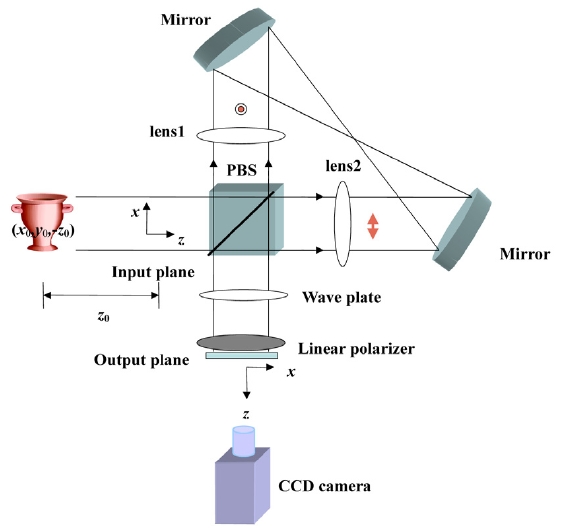
In the proposed modification of the triangular interferometer, we adjust the relative phase between two optical waves that travel the triangular interferometer in clockwise (cw) and counterclockwise (ccw) directions. This is done
by use of a polarizing beam splitter (PBS), a linear polarizer (LP), and a λ/4 wave plate (WP). Figure 1 shows the proposed system obtained with a modified triangular interferometer (MTI). Lens1 and lens2 have focal lengths of
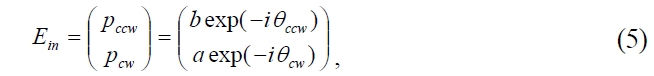
Both the input plane and the output plane are located at common focal planes of lens1 and lens2. In Fig. 1 we consider a single point of an incoherent object whose coordinate is given by (x0, y0, -z0), where z0 is positive (z0 is the distance from the object to the input plane). The complex amplitudes in front of a wave plate of the light that travels cw and ccw, respectively, are given by
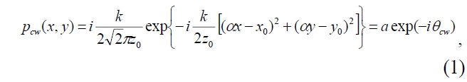
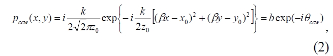
where
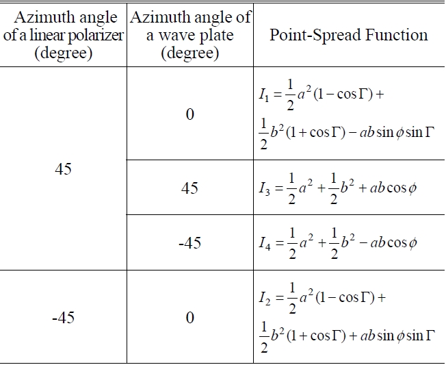
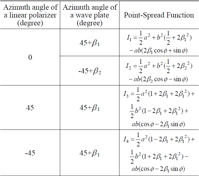
[TABLE 1.] Intensity patterns by combination of a wave plate and a linear polarizer
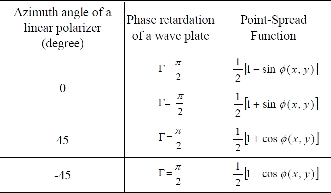
Intensity patterns by combination of a wave plate and a linear polarizer
See [6, 10] with respect to the above equations. By controlling four intensities either electronically or optically, we obtain the final complex hologram without bias:

Therefore, bias and twin images can be removed by the choice of four sequential sets of LP and WP and manipulation of the detected light intensities electronically.
III. PHASE ERROR OF INCOHERENT TRIANGULAR HOLOGRAPHY
The main potential sources of error in the MTI are the imperfections of the polarization elements and azimuth angle error of the polarization elements. We shall analyze the effects of these potential error sources one by one.
In Fig. 1, the Jones matrix [11] of output beam in the output plane is given by

where
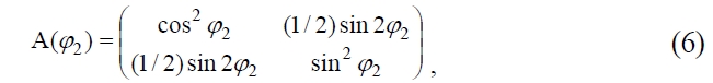
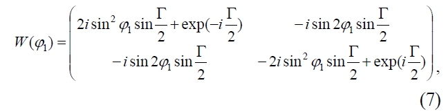
where

3.1. Phase Error Caused by the Imperfections of a Wave Plate
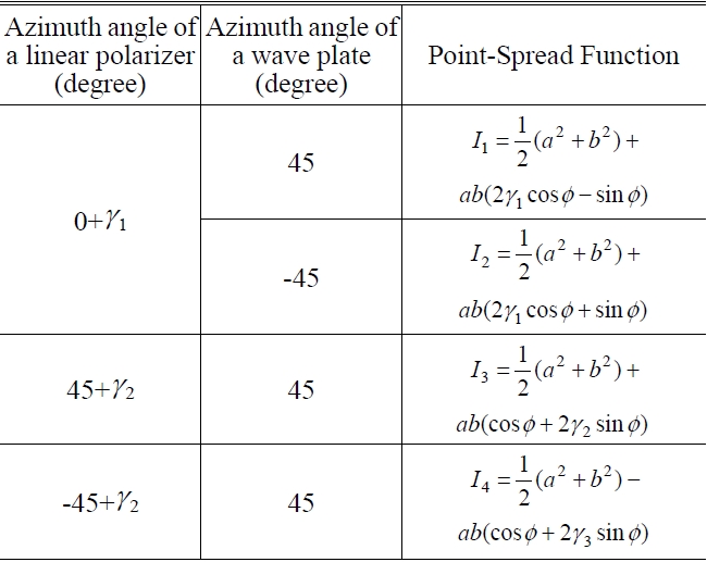
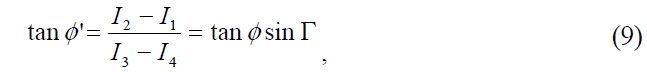
We shall deal mainly with the errors that are introduced by imperfections in the λ/4 plate. In this case, we assume that the azimuth angle error of the wave plate is zero. The phase error introduced by imperfections in the λ/4 plate can be obtained from four intensity patterns as listed in Table 2, which are obtained from Eqs. (4) to (8).
From Table 2, the phase difference
where
where

[TABLE 2.] Intensity patterns by combination of a wave plate and a linear polarizer

Intensity patterns by combination of a wave plate and a linear polarizer
Since

we can calculate the phase error that is due to the imperfections of a wave plate from Eqs. (11) and (12) as follows:

3.2. Phase Error Caused by the Azimuth Angle Error of a Wave Plate
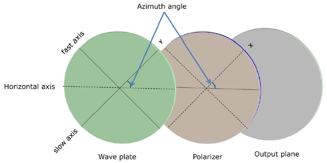
In this section, we shall deal with the phase error that is introduced by the azimuth angle error in the λ/4 plate. In this case, we assume that a wave plate is ideal and the azimuth angle errors of all polarization elements are zero except for a wave plate. The azimuth angle of a wave plate means the angle that the slow axis of a wave plate is rotated with respect to horizontal axis as shown in Fig. 2.
For
The phase error introduced by the azimuth angle error of a wave plate can be obtained from four intensity patterns as listed in Table 3.
By the same procedure as section 3.1, we obtain the phase error due to the azimuth angle of a wave plate as

where cot 2
If

Intensity patterns by combination of a wave plate and a linear polarizer considering only azimuth angle error of a wave plate
3.3. Phase error caused by the azimuth angle error of a linear polarizer
We deal with the phase error that is introduced by the azimuth angle error in the linear polarizer. In this case, we assume that a linear polarizer is ideal and the azimuth angle errors of all polarization elements are zero except for a linear polarizer. The azimuth angle of a linear polarizer means the angle that the x-axis of a linear polarizer is rotated with respect to horizontal axis as shown in Fig. 2.
For
The phase error introduced by the azimuth angle error of a linear polarizer can be obtained from four intensity patterns as listed in Table 4.
By the same procedure as section 3.1, we obtain the phase error caused by the azimuth angle of a linear polarizer as

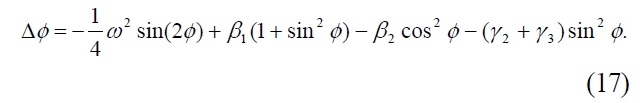
3.4. Total Phase Error Caused by the Polarization Components
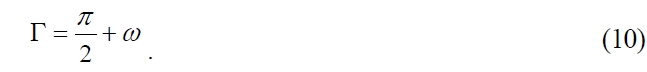
The total phase error by polarization components is written by adding Eqs. (13), (15), and (16) giving
In the extraction of the phase term using the combination

Intensity patterns by combination of a wave plate and a linear polarizer only azimuth angle error of a linear polarizer
of polarization elements, the phase error occurs. The retardation error of the commercially available wave plate makes the second-order error very small. Accordingly, the phase error in the MTI is mainly due to the azimuth angle errors of the polarization elements.
4.1. Imperfections of a Wave Plate
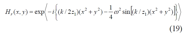
A point-source hologram considering the phase error of Eq. (13) due to a wave plate is described as

where
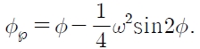
For simplicity, we now consider a single point-source hologram whose coordinate (
According to Fresnel diffraction theory, the complex amplitude is given by
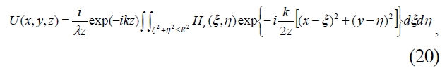
where R is the radius of the hologram size. Considering the complex amplitude in the z-axis direction, Eq. (20) becomes
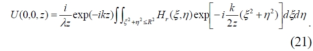
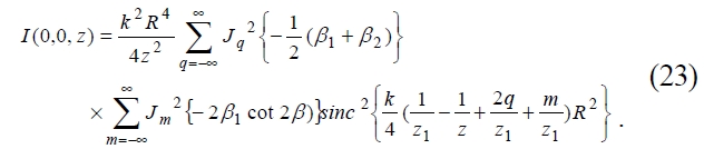
If there is negligible overlap of the various diffracted terms, the corresponding intensity of the reconstructed image of point-source hologram along the z-axis direction becomes
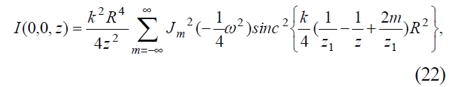
where
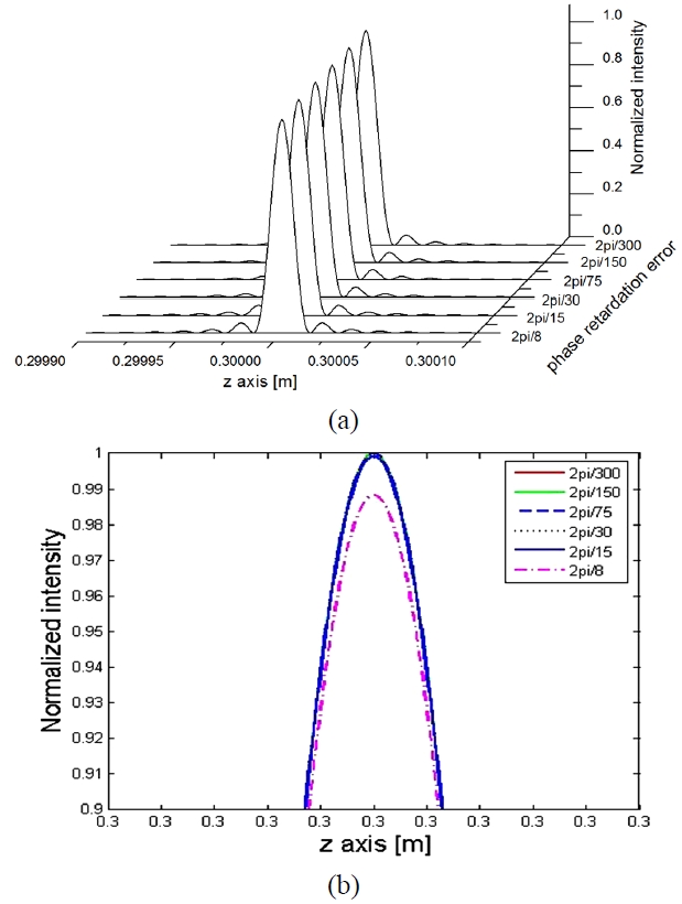
The intensity patterns corresponding to Eq. (22) are plotted together in Fig. 3; the phase retardation errors of a wave plate(i.e.
Figure 3 (a) and (b) represent the 3-D plot of normalized intensity for the phase retardation errors caused by the
imperfections of a wave plate and the front view for the normalized intensity beyond 0.9 in Fig. 3 (a), respectively. As shown in Fig. 3, as phase retardation error increases, the intensity of reconstructed image has very little change. When the phase retardation errors range from 2π/300 to 2π/8, the normalized intensity of reconstructed image is down by about 1.2%. This means that the reconstructed image of complex hologram created by using the commercially available wave plate is not influenced by the phase retardation error of a wave plate.
4.2. Azimuth Angle Error of a Wave Plate
By the same procedure as section 4.1, we obtain the corresponding intensity of the reconstructed image of point-source hologram along the z-axis direction using the phase error of Eq. (14) as
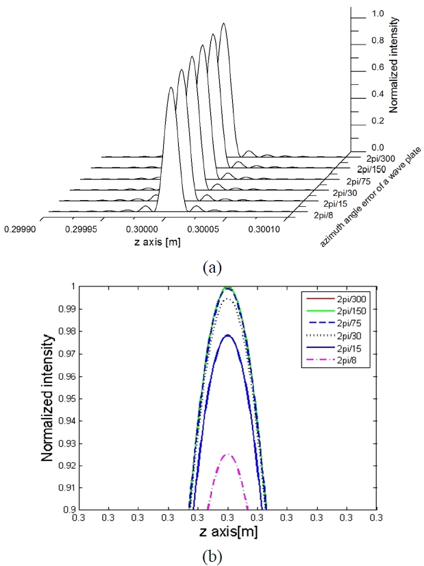
The intensity patterns corresponding to Eq. (23) are plotted together in Fig. 4; the azimuth angle errors of a wave plate(i.e.
represent 3-D plot of normalized intensity for the azimuth angle error of a wave plate and the front view for the normalized intensity beyond 0.9 in Fig. 4 (a), respectively.
As shown in Fig. 4, as azimuth angle error increases, the intensity of the reconstructed image decreases. When the azimuth angle errors of a wave plate range from 2π/300 to 2π/8, the normalized intensity of the reconstructed image is down by about 7.5%. Decrease of the normalized intensity caused by azimuth angle error of a wave plate is nearly 7 times that caused by imperfections of a wave plate. This means that the reconstructed image of the complex hologram is influenced by not imperfection of a wave plate but the azimuth angle error of a wave plate.
4.3. Azimuth Angle Error of a Linear Polarizer
By the same procedure as section 4.1, we obtain the corresponding intensity of the reconstructed image of the point-source hologram along the z-axis direction using the phase error of Eq. (15) as
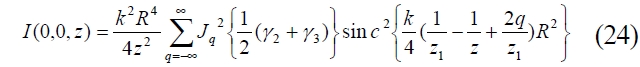
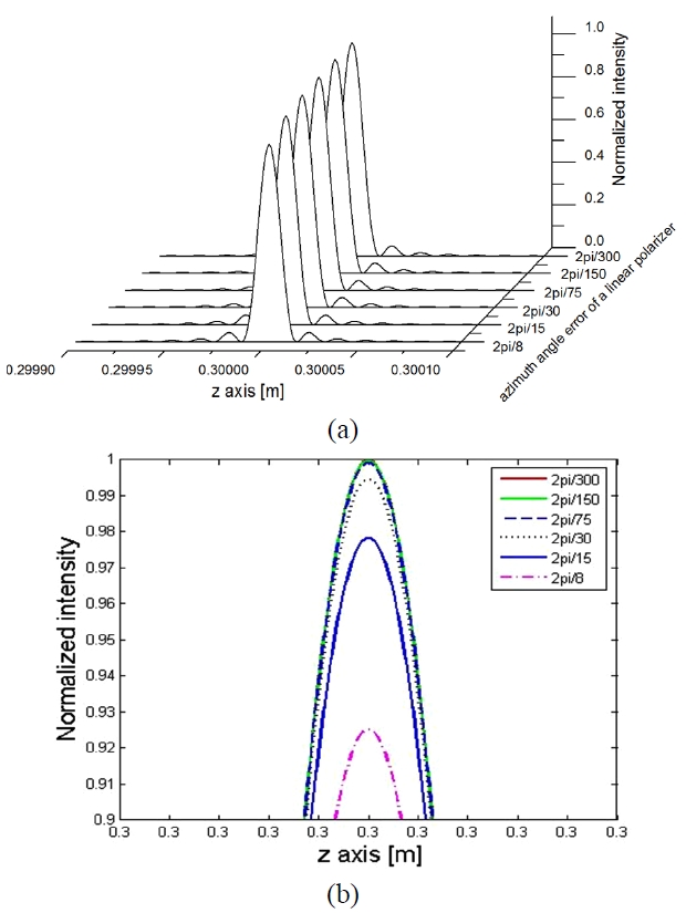
The intensity patterns corresponding to Eq. (24) are plotted together in Fig. 5; the azimuth angle errors of a linear polarizer (i.e.
As shown in Fig. 5, as azimuth angle error increases, the intensity of the reconstructed image decreases. When the azimuth angle errors of the linear polarizer range from 2π/300 to 2π/8, the normalized intensity of the reconstructed image is down by about 7.5%. Decrease of the normalized intensity caused by azimuth angle error of a linear polarizer is nearly 7 times that caused by imperfections of a wave plate. This means that the reconstructed image of the complex hologram is influenced by the azimuth angle error of a linear polarizer. Figure 4 and 5 are pretty similar. From the results, we conclude that the azimuth angle error of polarization components has a similar influence on image reconstruction of the complex hologram.
By the same procedure as section 4.1, we obtain the corresponding intensity of the reconstructed image of the point-source hologram along the z-axis direction using the phase error of Eq. (16) as
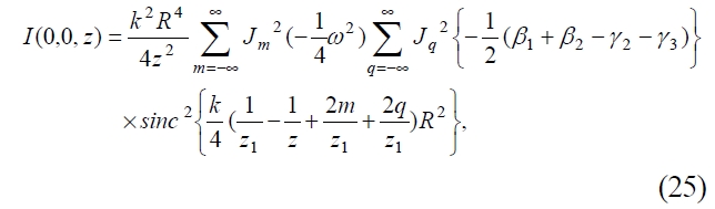
where
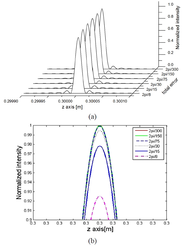
The intensity patterns corresponding to Eq. (25) are plotted together in Fig. 6, in which the phase retardation error of a wave plate(i.e.
Figure 6 (a) and (b) represent 3-D plot for the total error sum and the front view for the normalized intensity beyond 0.9 in Fig. 6 (a), respectively. As shown in Fig. 6, as total error sum increases, the intensity of the reconstructed image decreases. When the total errors range from 2π/300 to 2π/8, the normalized intensity is down by about 7.5%.
Considering the Rayleigh criterion, we can conclude that the longitudinal resolution of the reconstructed image decreases as the total phase error increases because the total phase error is proportional to the error sum. From the results, it can be seen that the resolving power of an incoherent triangular holography in the longitudinal direction is inversely proportional to the total error. In conclusion, the minimum separation of a three-dimensional object that can be resolved by the incoherent triangular interferometer is proportional to the phase error of the polarization elements.
We derived the point-spread function of the reconstructed image from a point-source complex hologram, which includes phase error caused by polarization components, in the longitudinal direction of the point-spread function and analyzed the effect of the error sources of polarization components on the corresponding intensity of reconstructed image about the phase retardation error of a wave plate, the azimuth angle error of a wave plate, and the azimuth angle error of a linear polarizer.
As phase retardation error of a wave plate increases, the intensity of the reconstructed image changes very little. On the other hand, as azimuth angle error of polarization components increases, the intensity of the reconstructed image decreases.
From the results, the commercially available wave plates don’t have an influence on image reconstruction of the complex hologram. The quality of the reconstructed image in incoherent triangular holography is affected by the azimuth angle errors of the polarization elements, which have a similar influence on image reconstruction of the complex hologram.