A tidal wave and great earthquake caused the catastrophic disaster in the shore of East Japan on March 11, 2011. In particular, the First nuclear power plant in Fukushima Prefecture suffered destructive damage by the tidal wave. Nuclear reactor1-3 experienced meltdown resulting in evacuation of residents within a 20 km radius of the power plant. Although the promotion of nuclear power generation was dominant to that point in time, the exploitation of renewable energy has gained popularity due to global warming and the decrease of the fossil fuel since the great earthquake disaster in Eastern Japan. In particular, solar cell research has attracted much attention worldwide, specially for green energy production.
The use of silicon-based solar energy converters has become dominant in solar cell technology over the past few decades. Many photovoltaic modules are made of silicon materials, such as crystalline silicon (single-crystalline or multicrystalline) and
amorphous silicon. However, high production costs and sophisticated fabrication processes have motivated researchers to venture for environmentally-friendly, cost-effective, and simpler fabrication processes using polymeric materials [1,2]. Polymer solar cells have attracted much attention due to their potential for low-cost solar energy harvesting and their applications to flexible, light-weight and large-area devices [3-5]. Since the solution technique is possible, the solar cell price will be low [6]. Until now, the power conversion efficiency exceeding 4.7-7% is attained using materials with a low band gap and a broadband absorption wavelength [7-9]. In this paper we report on an organic thin film solar cell with improved surface smoothness of an active layer and a TiOx buffer layer prepared using a solution technique that attained a power conversion efficiency of 5.07%.
1.1 Acceptor and donor molecules
1.1.1 Donor molecule
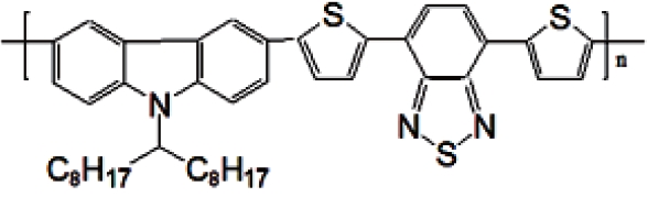
The electron-rich thiophene unit is the most important key element, and it is ubiquitously incorporated into D-A conjugated polymers to adjust the optical and electronic properties to optimal levels. Recently, poly (2,7-carbazole) derivatives have gained momentum as a class of promising alternative materials to poly (3-hexylthiophene) (P3HT) in organic solar cell applications. Among them, poly[[9-(1-octylnonyl)-9H-carbazole-2.7-diyl]-2.5-thiophenediyl-2.1.3-benzothiadiazole-4.7-diyl-2.5-thio phenediyl] (PCDTBT) has a relatively deeper highest occupied molecular orbital (HOMO) of 5.45 eV compared to the HOMO of 5.1 eV of the P3HT. PCDTBT is the new material and narrow band gap polymer. Moreover, since the electron and hole generation rate is high and the mobility of the electron and hole is also high, a short-circuit current increase is expected.
1.1.2 Acceptor molecule
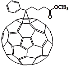
Fullerenes are highly symmetrical cage-shaped molecules constituted only by carbon atoms, which have been thoroughly studied during the last two decades [10]. Blending conjugated polymers with electron acceptors such as fullerenes, is a very efficient way to break apart photoexcited excitons into free charge carriers. Since the discovery of heterojunction PVCs, fullerene (mainly C60) and its derivative, [6,6]-phenyl-C61-butyric acid
methyl ester (PC61BM), or [6,6]-phenyl-C71-butyric acid methyl ester (PC71BM) are widely utilized acceptors providing PCE in the range of 2-5% when combined with selected donor materials. The fullerene PCBM core readily accepts electrons from a wide range of organic donor materials and exhibits high electron nobilities even in composite form. Despite their success, it is a non-ideal material for photovoltaic applications due to its weak absorption in the visible spectrum and excessively deeplying LUMO level, which results in needless energy loss during electron transfer and so limits the efficiencies of the final devices their open-circuit voltages in particular. In this study, we used the soluble PC71BM, the chemical structure of which is shown in Fig. 2.
In the present work, the spin-coating method was used to prepare the thin film, and the vacuum evaporation method was used to prepare the top (Al) electrode. The ITO substrate was patterned by a mask to create the electrode area. After that, the surface of the ITO substrate was washed with the supersonic for 10 minutes with the surfactant, purified water, acetone and then ethanol. After that point, the PEDOT: PSS thin film was fabricated using a spin-coating method on the ITO substrate as the buffer layer of the p-type donor under a 4,000 rpm rotational speed for 30 sec. The buffer layer was then annealed at 110℃ for 10 minutes under a nitrogen atmosphere. The PCDTBT/PC71BM (4.5 mg/18 mg) mixture solution was dissolved in chlorobenzene (1 mL). After that, the active layers of the PCDTBT/PC71BM bulk hetero junction thin films were prepared on the PEDOT-PSS thin films using the single spin-coating method under a 1,000 rpm rotational speed for 90 sec. On the surface of the active layer, the TiOx thin film of the buffer layer was made using the spin-coating method as an acceptor. The cathode electrode thin film was then deposited with aluminum by a physical vapor deposition (PVD) method.
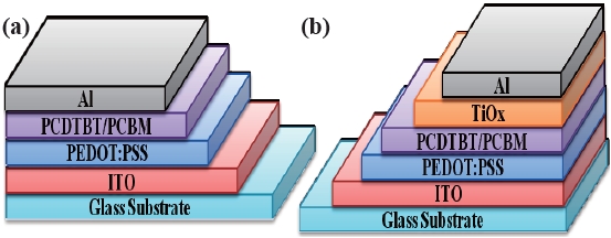
The performances of the organic thin film solar cells fabricated with an active PCDTBT/PCBM layer under various preparatory conditions were evaluated using a solar simulator (AM 1.5:100 mw/cm2). Figure 3 shows the cross sectional structure of two kinds of organic thin film solar cells. Figure 3(a) shows the element structure without a TiOx insertion layer and Fig. 3(b) shows the element structure with a TiOx insertion layer.
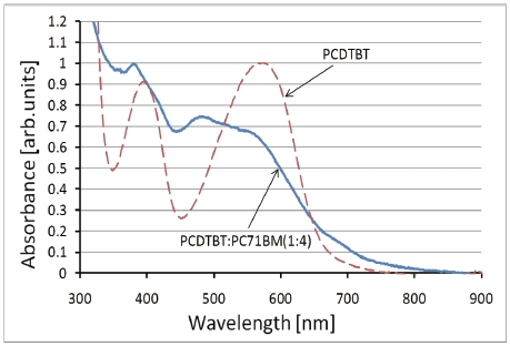
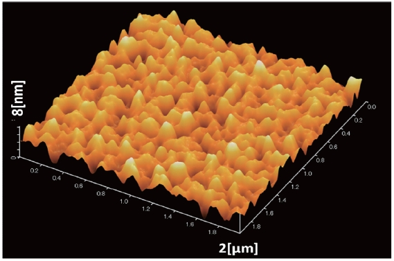
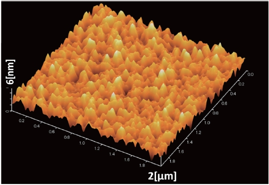
The ultraviolet-visible (UV-vis) spectra of PCDTBT/PCBM thin films were recorded in the range 300-900 nm using a spectrophotometer. The surface of the PCDTBT: PCBM active layer of an ITO/PEDOT-PSS/PCDTBT-PCBM thin layer and the surface of the TiOx thin layer of a ITO/PEDOT-PSS/PCDTBT-PCBM/TiOx thin layer were observed using atomic force microscopy (AFM).
Figure 4 shows the UV-vis spectra of the PCDTBT thin film and
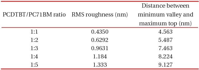
[Table 1.] The RMS roughness values of PCDTPT/PC71BM composite thin films.

The RMS roughness values of PCDTPT/PC71BM composite thin films.
the PCDTBT: PC71BM composite thin film (1:4). The peak at 580 nm of the PCDTBT thin film decreases in the spectrum of the PCDTBT-PC71BM composite thin film and a new peak appears around 500 nm. These results show the mixed state of a PCDTBT and a PC71BM molecule in the PCDTBT-PC71BM composite thin film.
Table 1 shows the RMS roughness obtained from the AFM imaging (Figs. 5,6), and the value acquired from the differences between mountains and valleys. From the AFM images, the RMS roughness, and the difference between minimum bottom and maximum top were observed. The increase of the ratio of PC71BM forms larger aggregation than the low ratio of PC71BM . This finding suggests that the network of PC71BM is good and has high electron mobility. The power conversion efficiency of the organic thin film solar cell can be expected to improv by increasing the PC71BM ratio. However, if the PC71BM ratio of a PCDTBT:PC71BM composite thin film increases and the of PC71BM aggregation increases the interpenetrating network of donor molecules and acceptor molecules is disturbed.
The current-voltage (I-V) characteristics of the devices were measured inside the glove box using an Advantest-R-6441
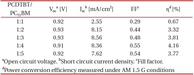
[Table 2.] Organic thin film solar cell performance parameters against the PCDTBT/PC71BM ratio.

Organic thin film solar cell performance parameters against the PCDTBT/PC71BM ratio.
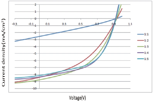
source/measure unit under AM 1.5 G illuminations at 100 mWcm-2. Suitable electrical contacts were developed for the I-V measurements. ITO was taken as the positive contact, while the vacuum-deposited aluminum served as the negative contact. Figure 7 shows the dependence of the composite ratio of PCDTBT-PC71BM thin film of the J-V characteristics. Table 2 shows the organic thin film solar cell performance parameters against the ratio of PCDTBT/PC71BM .
The PCDTBT/PC71BM composite showed an increase in the photocurrent with the increasing C71 contact (up to a certain limit). The addition of C71 allows ultra-fast photo induced electron transfer from the PCDTBT to the C71 and enhances the charge carrier generation in the PCDTBT by preventing recombination. The fill factor also increases with an increasing concentration of C71. The I-V measurements confirmed that the current rate increase with increasing concentration of C71 up to 1:4. Therefore 1:4 PCDTBT/PC71BM composite ratios were found to be the optimum choice. This finding also indicates that the optimal interpenetrating networks of donor molecules and acceptor mol-

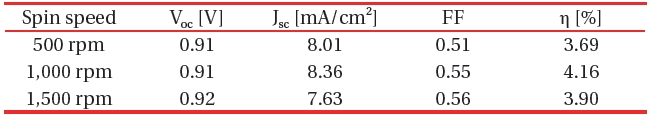
Organic thin film solar cell performance parameters against the spin speed of the PCDTBT/PC71BM active layer.
[Fig. 8.] J-V characteristics of organic solar cell without or with a TiOx thin film.
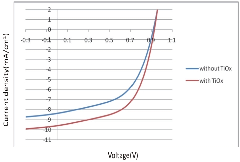
J-V characteristics of organic solar cell without or with a TiOx thin film.
ecules in the active layer exist according to the PCDTBT/PC71BM ratio.
Table 3 shows the organic thin film solar cell performance parameters against the spin speed of the PCDTBT/PC71BM active layer. The maximum power conversion efficiency is obtained at a spin speed of 1,000 rpm indicating that the optimal thickness of the active layer exists at 1,000 rpm.
We reported here that new devices fabricated with a TiOx layer between the PCDTBT/PC71BM and the Al layer show improved performance in terms of Jsc and the power conversion efficiency.
Our finding indicate that the PCDTBT and PC71BM interface is enhanced by increasing the PC71BM ratio. The organic solar cell prepared using the 1:4 (PCDTBT:PC71BM ) ratio and a 1000-rpm spin speed is the PCE of 4.16%. The Jsc of organic thin film solar
[Table 4.] Organic thin film solar cell performance parameters without or with a TiOx thin film.
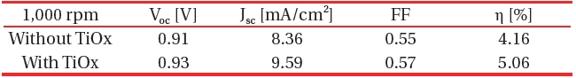
Organic thin film solar cell performance parameters without or with a TiOx thin film.
cell increases by insertion of the TiOx thin film, the performance parameters are improved, and the PCE yields a conversion efficiency of 5.06%.