Wireless sensors have recently become very popular, due to their portability and wide range of applications in remote and physically inaccessible locations. These sensors require a compact, low cost, long operating life and light-weight energy source [1]. Usually, fixed energy alternatives, such as batteries and fuel cells are used as a power source for those sensors. However, batteries have the limitation of short operational life. Therefore, it is impractical to use batteries as an energy source for applications that require sensors to be installed for long duration or in physically inaccessible locations, such as biomedical implants and structure embedded micro sensors [2]. Moreover, recent advances in battery energy density are lagging compared with advances in micro-system technology [3]. As a result, the battery size is often more bulky than the system itself. Energy harvesting from ambient energy sources is a possible alternative to batteries, converting energy from an existing source within their environment into usable electrical energy. Therefore, a fully self-sustaining system can be implemented by using energy harvesting techniques; and this will also reduce the problems of interconnection, electronic noise and control complexity. There are several environmental energy sources such as thermal, solar, tidal and wave energy, acoustic noise, wind and vibration [4]. Vibration is more attractive, since it is inherent in nature [5,6].
In this work, we designed an AA size electromagnetic energy harvester. Pioneering work on AA size transducers has been carried out by research groups [7,8], who proposed two AA size energy harvesters using a spring mass system, which is capable of producing a maximum 120 μW and 830 μW power at 70.5 Hz and 100 Hz resonance frequency, respectively. Korla et al. [9] described a generator of the same size using a piezoelectric transduction technique, which was able to generate a power of 625 μW at 50 Hz resonance frequency. However, resonance frequency of the stated harvesters is very high. On the other hand, ambient vibration frequencies are very low (1-10 Hz) [6]. Efforts have also been conducted to reduce the operating frequency of harvesters; e.g. using a frequency up-conversion technique, it is possible to operate the transducer at 25 Hz resonance frequency [4]. However, it can generate only 3.79 μW maximum power. Tzeno et al. [10] developed a bi-stable mechanical structure to scavenge energy from a low frequency environment. They showed that their device could harvest a peak power of 288 μW at 10 Hz resonance frequency, but the system input acceleration is very high (9.8 m/ s2).
In this paper, we present the design and analysis of an AA size electromagnetic energy harvester that uses a magnetic spring. A
magnetic spring type generator has the advantages of low resonance frequency, simple construction process and easy vibration under off-resonance conditions [11]. The output of the transducer is maximized by optimizing the fixed magnet size, coil width, coil position, and load resistance. Moreover, nonlinear behavior of the harvester is reduced, by increasing the height of the moving magnet compared with the coil width.
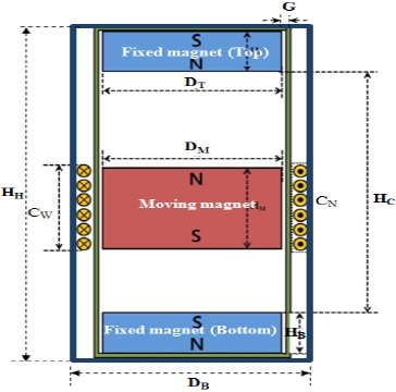
Figure 1 is a schematic diagram of a magnetic spring generator. A moving magnet is inserted into a hollow plastic straw. Then, two opposite poles fixed magnets have been placed vertically, in such a way that each pair of facing surfaces of magnets has the same pole. A coil of enamel coated copper wire is wrapped horizontally around the outer casing of the plastic straw. When an external force is applied to the structure, the middle magnet starts to oscillate, due to magnetic repulsion of the two fixed magnets and hence AC voltage will be induced in the coil.
The proposed energy harvester can be described by a spring mass system. Assume that a sinusoidal force
where,
The force between top and moving magnet can be expressed as [12]:

where,
Similarly, the force between bottom and moving magnet is:

So, the spring constant (

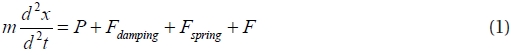
Equation (1) can be written as:


where,
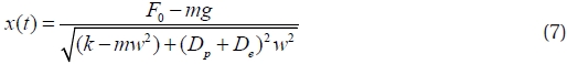
Therefore, the solution of the displacement of (6) can be formulated as:
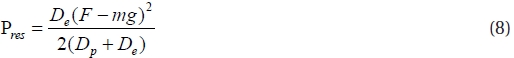
The average generated power at resonance (i.e. ω=ωn=√(k/m)) can be written as:
ANSYS 2D finite element analysis was used to evaluate the nonlinear behavior of the flux density across the coil surface. For convenience and ease of fabrication, an air gap of 1 mm was chosen between the moving magnet and the inner surface of the cylinder.
The average flux density across the coil surface was calculated by dividing the surface into 15 paths and taking the average for
[Table 1.] Simulation parameters.
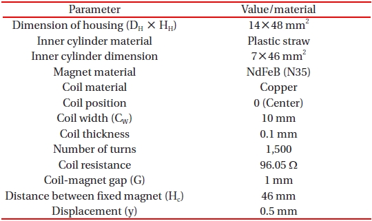
Simulation parameters.
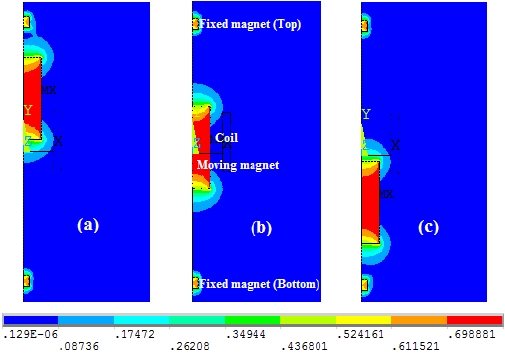
moving magnet positions in the space between the top and bottom fixed magnets. Figures 3(a)-(c) show the patterns of magnetic flux density for three positions of moving magnets at 10 mm, 20 mm and 30 mm from the top magnet, respectively. The simulation parameters are shown in Table 1.
The next section discusses the optimization of output by maximizing the moving mass, fixed magnet sizes, coil width, coil position and load resistance in detail.
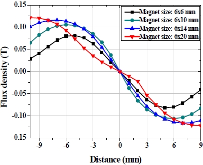
When the axial movement of the magnet is less than the coil width, the response (i.e. flux density vs. distance) shows some nonlinearity towards the ends [11]. The nonlinearity can be reduced by increasing the axial movement of the magnet, since increase of the moving magnet mass reduces the linear stiffness coefficient. As observed from Fig. 3, the response shows more linearity with the increase of size of the moving magnet.
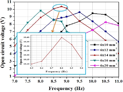
During optimization, we find out the output voltage for different sizes of moving magnet by keeping all other parameters (e.g. fixed magnet sizes, coil width and coil position) constant. As the size of the moving magnet increases, flux density across the coil also increases, however, displacement speed of the moving magnet decreases [13,14]. Hence, a trade-off is required between the flux density and the moving magnet’s displacement speed, to optimize the output voltage. As depicted in Fig. 4, a maximum voltage of 10.4 V is obtained for a 6×14 mm2 moving magnet size at 8.8 Hz resonance frequency.
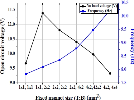
Similarly, for the optimization of the fixed magnet at the top and bottom ends of the tube, a trade-off is required between the
flux density and mass displacement. As shown in Fig. 5, when a 1x1 mm2 size magnet is used at the top and bottom, the device operates at a lowest resonance frequency (7.8 Hz). However, at this time, the output voltage is low (9.67 V). An optimum voltage of 11.4 V is obtained when a 1×1 mm2 and 2×2 mm2 size magnet is used at the top and bottom, respectively.
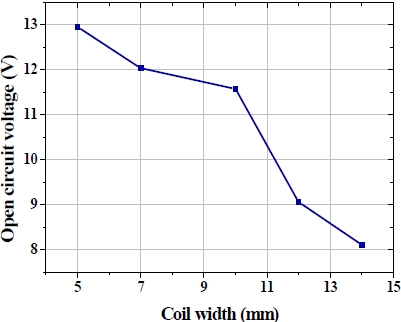
Figure 6 shows the open circuit voltage for different coil widths. As observed, a smaller coil width (5 mm) gives a higher output voltage (12.96 V), indicating that there is less possibility of flux enclosing than that with a larger coil width. Flux lines that are totally enclosed by the coil do not have any contribution to the resultant output voltage, because the total flux linkage for
[Table 2.] Optimized parameters of proposed harvester.
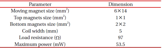
Optimized parameters of proposed harvester.
those flux lines with the coil is constant [15].
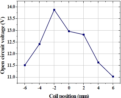
For our model, the resting point of the moving magnet is slightly lower than the middle position, due to gravitational force. Under the excitation, the speed of the moving magnet is high around the resting point, and gradually decreases towards the end of the tube, due to the opposite poles of the fixed magnets at the top and bottom. Fig. 7 shows the variation of output voltage at different coil centre positions from the middle point of the tube. As can be seen, the output reaches its maximum value of 13.88 V when the position is 2 mm below the middle point, since the speed of the moving magnet is maximum around this position.
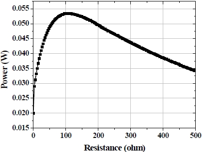
The output power was calculated by Matlab simulation, using a variable resistor (0-500 Ω). A maximum average power of 53.5 mW was obtained at 97 Ω load resistance, as shown in Fig. 8. The optimized parameters of the proposed AA size electromagnetic energy harvester are given in Table 2.
In this paper, an AA size electromagnetic energy harvester has been presented, which can harvest energy from low frequency environmental vibrations. The output voltage of the transducer was maximized by optimizing the moving magnet size, fixed magnet sizes, and coil width. Moreover, nonlinear behavior of the generator was reduced, by increasing the height of the moving magnet relative to the coil width. The optimized harvester generated a maximum average power of 53.5 mW with an input displacement of 0.5 mm at 8.1 Hz frequency. The main advantages of the proposed magnetic spring type energy harvester are simple operation, low cost and long operating life. Furthermore, the generator is able to operate at 8.1 Hz resonance frequency. Therefore, the proposed generator would be very useful for supplying power in health care and environmental monitoring sensor system applications.