In recent years, many reflective electronic displays using different principles have been reported [1,2]. Some of these have been fabricated as a prototype and even commercialized [3,4]. Especially, electronic paper display based on electrophoresis has been successfully applied to electronic books having low power consumption, low product cost, and ease of viewing without a backlight unit [5]. The reflective electronic display is appropriate for signboards or electronic books, which permit a low resolution and a low contrast ratio with much less expense, and greater visibility compared to emissive-type displays including liquid crystal displays [7]. However, the demand for performance improvement regarding lifetime, bistability, and slow response time remains unchanged. Because of these disadvantages, it is believed that the market penetration of electronic paper based on electrophoretic ink has failed to meet expectations.
Another reflective display designed to overcome these shortcomings, namely response-liquid powder display (QR-LPD) [8], was reported in 2003. Since the particles in this type move freely in the air within their respective cell, its response time is extremely fast (less than 0.5 ms); hence, the passive driving method is possible for a small-sized display panel or a signage of a small number of pixels. Although this display device has a fast response time sufficient to be used in a fast sequence of static images (for example, an electronic book), a major cause of the high driving voltage and the short lifetime has not been analyzed. In this work, various forces acting on a particle in a cell and the clumping phenomena inducing degradation of the optical property are analyzed. It is believed that this analysis will contribute to the performance improvement for reflective electronic displays.
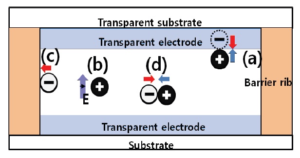
The electrically positive and negative particles in a cell of QRLPD are surrounded by conductive electrodes on the upper and the lower substrate as well as the dielectric materials of the bar-
rier ribs. Particles in the above cell are attached to or detached from the other materials by various forces [5]. This is illustrated in Fig. 1.
First, there is an image force acting between the particles and electrode, which allows a bi-stability to maintain the formed image without a power source. This force is shown in (a) of Fig. 1. In the equation regarding the image force, F=q2/16πεx2, where F is the force between an electric charge and its image charge, q is the amount of the electric charge of the particle, x is the permittivity, and x is the distance of the conductor and the position of a charge in a particle. A large quantity of electric charge results in sufficient bi-stability but requires a large electric field to detach the particle from the electrode because of its large image charge. So, the appropriate electronic charge of a particle must be defined and the defined charge determines the driving voltage of a display panel.
Second, there is a force related to the potential energy through a bias voltage and the kinetic energy for a particle as shown in (b) of Fig. 1, which is explained by equation,
, such that
, where V is the applied voltage, m is the mass of the particle, and v is the velocity of the particle. This well-known equation shows the transition of electric energy to kinetic energy for a particle. From this equation, a large value of the ratio q/m requires a small electric field with a constant velocity of a particle, while it requires a large electric field in regards to image force. Also, the particles at nearby dielectric ribs experience a force due to the van der Waals force as shown in (c) of Fig. 1. This force also exists between the dielectric surfaces of the neighboring particles. Furthermore there is a Coulomb’s force between opposite or same signed particles as shown in (d) of Fig. 1.
As a consequence, it is believed that a large q/m ratio is advantageous to the bi-stability and kinetic energy, but conversely demands a high driving voltage to overcome the large image force. So, it is important that the particles have a well-defined q/ m value in order to achieve a desirable bi-stability and low driving voltage.
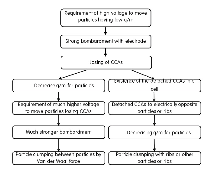
In case a driving voltage is determined with sufficient high value to move particles having a small q/m value, the particles having a large q/m value crash into the opposite electrode with a high speed at the driving voltage, which is absolutely high, resulting in the loss of electrically charged material consisting of charge control agents (CCAs) and thus finally become nonmovable particles with small q/m values. These non-movable particles were changed to have a small q/m induced clumping phenomena with neighboring particles or ribs by the above Van der Waals force. If the driving voltage is increased to move these non-movable particles, much stronger bombardments occur and most of the particles are clumped. These clumping processes are shown in the left line in Fig. 2. Also, the lost CCAs exist anywhere in the cell, so they contribute to the operation and clumping phenomena by attaching themselves to the oppositely charged particles or ribs as shown in the right line of Fig. 2.
For this study, charged particles and pieces of indium tin oxide (ITO) coated glass substrates are prepared. In this experiment, the white particle consists of TiO2, polymer, and CCA (-), while the black particle is made of carbon black, polymer, and CCA (+); these particles were dispersed in methyl ethyl ketone (MEK). The fluidity of these particles was controlled by the addition of nano-sized silica. The CCAs provide a particle with a permanent electric charge. For the fabrication by the simple particle-loading method, ribs are formed with a height of 40 μm and 70 μm, which were used as the upper and lower substrates, respectively.
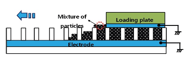
A sample panel according to the simple particle-insertion process is fabricated as shown in Fig. 3. By using a particle-removing roller, the final layers for the mixture of particles were set to be approximately 3.5 layers. Then, the thickness of bonders for combining two substrates is about 10 μm. The width of a rib is 30 μm, the cell gap is 116-120 μm, the cell size is 220 μm × 220 μm, the q/m value of the black particles is +1.8 μC/g and that for the white particles is -4.3 μC/g, and the average particle diameter is 20 μm. To neutralize the mixture of the positive and negative particles, it is left in the mixed condition for several days. To observe and ascertain the clumping phenomena, microscopic photographs showing clumped particles are obtained and response time of the fabricated panel is measured by a photodiode and a corresponding measurement system.
Almost non-movable particles can move at a large electric field so that the reflectivity is generally proportional to the amplitude of a driving voltage. But this relationship is broken following
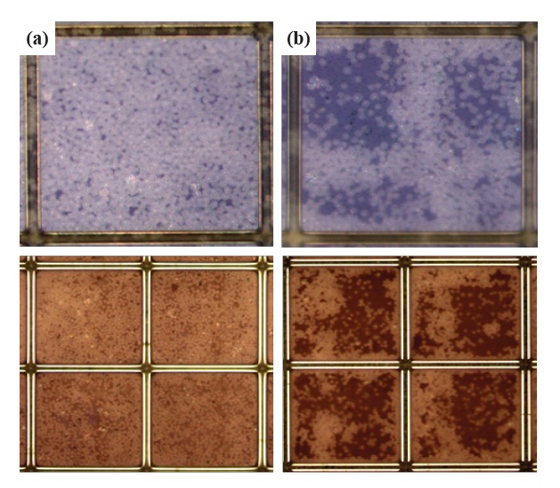
the number of driving times, which is defined as the lifetime of a panel. Most of the causes responsible for shortening the lifetime are regarded to the clumping phenomena as explained in Fig. 2. The clumped particles in a cell are observed as shown in Fig. 4(b). Fig. 4(a) shows non-clumped particles and (b) shows clumped particles in a cell. As shown in these photographs, the clumping process irregularly proceeded in neighboring particles or nearby ribs.
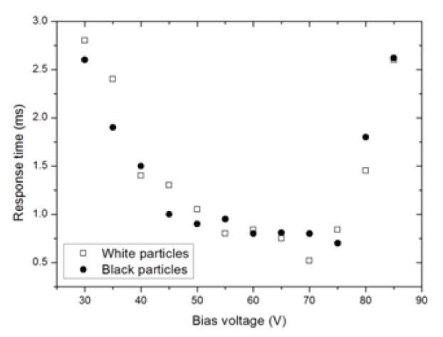
Particle-clumping induces a decrease in the value of q/m so that the response time of the particles in a panel is enlarged and the clumping process occurs abruptly. The increased response time is easily measured by a photodiode and a corresponding measurement system. Fig. 5 shows the resultant response time. In this figure, the minimum value of a response time (50-75 V) shows that most of the particles move with a maximum value of q/m because particle clumping has not begun at this bias voltage. This bias voltage is defined as a driving voltage. When the bias voltage is increased to 80-90 V, particle clumping occurs abruptly and the response time is increases sharply as shown in Fig. 4. This particle clumping is similarly observed after the number of driving times at the driving voltage (50-75 V). So, it is believed that the lowering of the driving voltage and the loading of the particles regarding the uniformly distributed q/m value are important in order to improve the lifetime for a charged particle type reflective display.
In this work, various forces acting on a particle in a cell and the clumping phenomena inducing the degradation of the optical property were analyzed. Particles in a cell are attached to or detached from other materials by image force, electric field, Coulomb’s force, and Van der Waals’ force. Through these forces, the moving particles form an image but induce clumping phenomena. The particles having a large kinetic energy by a large q/
m value crash into the opposite electrode with high speed at the driving voltage and quickly lose electrically charged material and the lost CCAs exist anywhere within the cell, thus contributing to the unstable operation and clumping phenomena by attaching themselves to oppositely charged particles or ribs. The clumped particles in a cell were observed by microscopic photographs. The clumping process irregularly proceeded in neighboring particles or nearby ribs. Particle clumping induces a decrease in the value of q/m so that the response time of the particles in a panel is enlarged and the clumping process occurs abruptly.
The increased response time was measured by using a photodiode and a corresponding measurement system. When the bias voltage was increased to 0.68-0.76 V/μm, particle clumping occurred abruptly and the response time increased sharply. This particle clumping is similarly observed after the number of driving times at the driving voltage. Thus, it is believed that the lowering of the driving voltage and the loading of the particles in regards to the uniformly distributed q/m value are important to improve the lifetime of a charged particle-type reflective display. Finally, it is believed that this analysis will contribute to the performance improvement ofreflective electronic displays.