People have been accustomed to reading paper-based books for a long time. Reading on paper is felt to be more convenient and offer less eyestrain, compared to reading contents on an emissive display screen. Emissive display screens are illegible under conditions of high external illumination, such as sunlight. So many reflective electronic paper displays (e-paper) have been reported; and some products, such as e-readers, have been commercialized to some degree [1,2]. However, in order to replace paper documents with e-paper, further technical development is required.
To improve screen performance, including response time, a quick response-liquid powder display (QR-LPD) was reported in 2003 [3]. Because the particles in the QR-LPD move freely in the air within their respective cells, its response time is extremely fast (less than 0.5 ms); hence, the passive driving method is applicable to a small-sized display panel, or a signage of a small number of pixels. Although this display device has a fast response time, sufficient to be used in a fast sequence of static images (for example, an electronic book), the inevitable problems of the high driving voltages and short lifetime, which are mainly caused by unstable particle movement or clumping phenomena, remain to be solved [4,5].
It is believed that the particles have a well-defined
improve driving voltage and lifetime [7]. A stable operation, suitable bi-stability effect, low driving voltage, and reliable lifetime can be obtained from the elimination of non-movable particles, simultaneously moving most of the particles in a cell at the minimum driving voltage without clumping phenomena, which is the ideal driving condition, and is the aim of this work.
In this work, a particle-insertion method, to prevent the nonmoving particles deviating from the appropriate range of
The non-moving particles deviating from the appropriate
In another particle-insertion method, namely the corona-gun method, charged particles are accelerated by the high voltage bias of over 200 V at the electrode of a corona gun, and are piled on the lower substrate [11]. This method, in common with the simple particle-loading method, cannot filter the non-moving particles; and, additionally, results in an increase in electric and mechanical damage of particles during the particle-insertion process [12]. Also, this method is not applicable to mass production, or to a large-sized panel. Consequently, these reported particle- insertion methods cannot filter out non-moving particles.
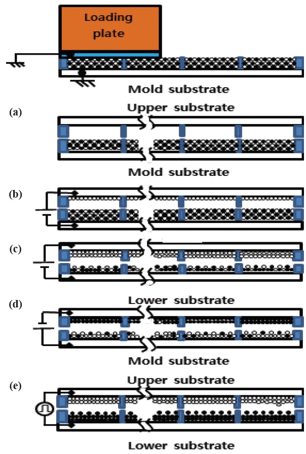
Figure 1 shows the process of the particle-moving method. First, the mixed particles of about 3 layers, controlled by the height of the rib, are inserted by the simple particle-loading method into the mold substrate, as shown in Fig. 1(a). This mold substrate, filled with a mixture of white (-) and black (+) particles, is aligned with the upper substrate, and an electric field is applied between the two substrates. The moving white particles in the mixture are moved to the opposite electrodes of the upper substrate, with the remainder of the non-moving white particles in the black particles of the mixture. This process is shown in Figs. 1(b) and (c). The same process is repeated as shown in Fig. 1(d), in which moved particles are not detached, because of the image force above. By repeated particle-moving processes, the moving white particles of about 2 layers are inserted into cells of the upper substrate. To move the electrically positive black particles of the mixture to the lower substrate, a reverse electric field is applied to the remainder of the non-moving black particles in the white particle of the mixture, as shown in Fig. 1(e). Finally, the upper substrate, filled with white (-) particles, and lower substrate, filled with black (+) particles, are combined by a bonding process, as shown in Fig. 1(f). As shown in this particle-insertion process, the non-moving particles are filtered away in the cells of the panel [13]. In the bonding process, particles in the cells are not detached by image force.
Two identical sample panels were fabricated by the two different particle-insertion processes. For this study, charged particles and pieces of indium tin oxide (ITO) coated glass substrates were prepared. In this experiment, the white particles consisted of TiO2, polymer, and CCA (-), while the black particles were made of carbon black, polymer, and CCA (+); these particles were dispersed in methyl ethyl ketone (MEK). The fluidity of these particles was controlled by the addition of nano-sized silica [14]. The CCAs provide a particle with a permanent electric charge. For fabrication by the simple particle-loading method, ribs were formed with a height of 40 μm and 70 μm, which were used as the upper and lower substrates, respectively.
By using a particle-removing roller, the final layers of the mixture of particles for the simple loading method were set to be about 3 layers. Then, the thickness of bonders for the combining of the two substrates was about 10 μm. To fabricate the panel by the particle-moving method, ribs were formed with heights of 55 μm for the mold substrate, and 48 μm for the upper and lower substrates. Therefore the cell gap between the lower and the upper electrode was about 116-120 μm for these two panels, by the previously reported simple particle-loading method, and the new particle-moving method. When the mixture of positive and negative particles was inserted into the mold substrate, they formed about 3 layers of particles. The applied electric field used to move the particles to the opposite electrodes of the upper and lower substrates was about 0.3-0.35 V/μm, after aligning the upper/lower substrate and the mold panel with spacers in the sides, to protect the mold substrate, and to control the distance between the upper/lower substrate and the mold substrate.
For both of the panels in this experiment, the width of all ribs was 30 μm, the cell size was 220 μm × 220 μm, the
the black particles was +1.8 μC/g and that for the white particles was -4.3 μC/g, and the average particle diameter was 20 μm. To neutralize the mixture of the positive and negative particles, it was left in the mixed condition for several days. To evaluate the movement of particles in a cell, the occupation rate (%) by moved particles on the electrode of the upper substrate was calculated from the image data of a microscopic photograph. It is believed that this evaluation method is desirable for a reflective electronic display using a switching operation of electrically opposite particles [15].
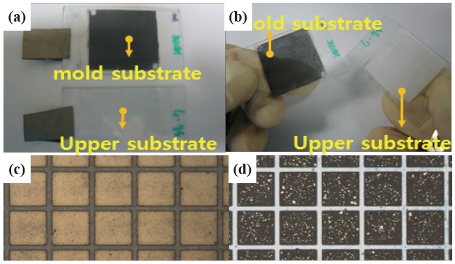
Photographs were obtained, according to the fabrication process of the particle-moving method of Fig. 1, as shown in Fig. 2. First, the mixture of both positive and negative particles was inserted into the cells on a mold substrate, as shown in the upper photograph of Fig. 2(a). The lower photograph of this figure is an empty upper substrate, which will become a front glass of the reflective electronic display panel. The rib pattern of these two substrates was designed equally. After the electric field between the two electrodes in Figs. 1(b) and (c) was applied, the movable white particles were moved to the upper substrate, as in Fig. 2(b), which shows the change to a white color. A microscopic photograph of the debonded upper panel is shown in Fig. 2(c). White particles in this photograph easily move in a cell at a defined electric field. For this experiment, the electric field was slowly increased, and about 2 layers of active white particles were finally obtained on the upper substrate. The number of layers was measured by microscopic observation of a backside image, using microscopy of the debonded panel. The particles that were moved at very low voltages needed to be removed, because the
As expected, there were non-moving white particles among the black particles on the mold substrate, as evidence of the filtering effect, of which a photograph is shown in Fig. 2(d). This figure shows photographs of the inside of the debonded mold substrate. These non-movable white particles would induce the clumping phenomena, high driving voltage, and undesirable optical properties, if they were inserted into the cell. To obtain another upper substrate filled with black particles for the lower substrate of the display panel, the same particle-moving method was applied. After alignment and bonding of the two substrates, filled with the black and the white particles, respectively, the reflective display panel was completed, and evaluated by a mea-
surement system.
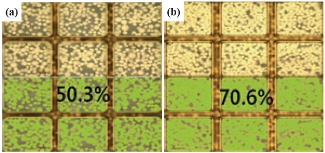
In order to evaluate the particle-moving method, another panel was fabricated by the simple particle-loading method, with the same parameters for particles and substrates. The particles inserted by this simple loading process were electrically neutral, so that the driving property was more stable than that attained by the corona gun method, but non-moving particles necessarily exist in the cell. Fig. 3 shows an evaluation example of an occupation area of the moved particles attached on their electrode. In these figures, the upper side is a microscopic image with white and black particles, and the lower side (green color) is obtained in the calculating process of an area occupied by the moved white particles on the electrode. In these images, white particles of the left side panel occupy 50.3%, and those of the right side panel occupy 70.6%. These results do not coincide with the reflectivity, because of surface reflectivity, an imperfect reflectivity of the white and black particle, a refraction at the interface between materials, and a transmitted light through the vacancy areas, which are pertinent to the reflective electronic display using movement of particles. So it is believed that this evaluation method is desirable.
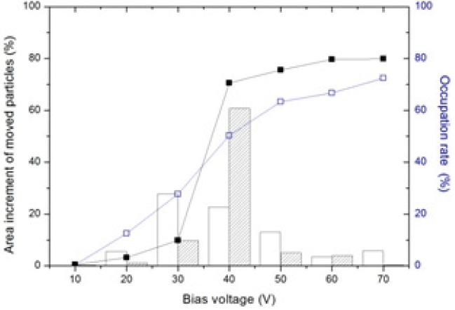
To evaluate the operating characteristics of these panels, driving information and occupation rate were obtained, as shown in Fig. 4. In this figure, the empty rectangles connected with a solid line are the occupation rate after aging pulses, of the panel fabricated by the simple particle-loading method, showing a linear curve with the bias voltage, because of the numbers of particles deviating from the appropriate
The filled rectangles connected with a solid line indicate the occupation rate after aging pulses of the panel fabricated by the particle-moving method, showing abrupt driving characteristics at any bias voltage (40 V), because of the removal of the nonmoving particles. In this case of the panel fabricated by the particle-moving method, the white particles abruptly moved at 40 V (about 0.34 V/μm), and the movements of particles after this voltage were nearly saturated. So this voltage was clearly regarded as the driving voltage, which was sufficient to move most of the particles, and a higher bias voltage was not required, preventing the above degradation by losing CCAs. The rectangle bars drawn at the occupation rate show increments of the occupation area. In this figure, the empty rectangle bars indicate an incremental area of a panel fabricated by the simple particleloading method, and the slashed rectangle bars show that fabricated by the particle-moving method. As shown in these figure, particles moved abruptly at a voltage of 40 V. As a result, most of the particles moved at 40 V, in the case of the particle-moving method.
The most important meaning of this experimentation is considered to be that an abrupt movement of the particles can be achieved at the driving voltage, by filtering the non-moving particles. Additionally, shades of grey for grey-scale images are achieved by pulse width modulation with a fixed driving voltage, so there need not be a linear increase of the reflectivity or occupation rate according to the bias voltage [16]. Regarding the above discussion, the particle-moving method contributes to improvements in the driving voltage, particle clumping, and reflectivity, which are expected to lead to a desirable lifetime.
A particle-insertion method that filters non-moving particles is analyzed, and the improved electrical and optical properties are evaluated. The particle-moving method removes particles that are not optimally charged, thus improving the performance by lowering the driving voltage, suppressing clumping phenomena, and enhancing the reflectivity. Photographs of non-moving white particles among the black particles on the mold substrate provide evidence of the filtering effect. In order to evaluate this method, two reflective display panels were fabricated by the particle- moving method and a previously reported method, with the same particle and panel condition. Comparing the two methods, it was ascertained that the particle-moving method induced a saturation of the moved particles at 40 V, whereas the previously reported method showed an uncertain driving voltage, because of the existence of non-moving particles that deviated from the appropriate
Also, these evaluation results were verified with the measurement of the occupation rate of the particles moved by an electric field. It is believed that this measurement provides a desirable evaluation method for a reflective electronic display. Grey-scale was achieved by pulse width modulation with a fixed driving voltage, so a linear increase of the reflectivity with bias voltage was unnecessary, and would have shortened the lifetime of the particles, by clumping of the non-moving particles.