Actuator devices contain nonlinearities such as friction, dead-zone, saturation, backlash, and hysteresis. Many of these nonlinearities are not continuous, but rather discontinuous functions or even dynamic models. Backlash is a dynamic nonlinearity and is common in mechanical and hydraulic systems. The undesirable effects of backlash are the main factors that severely limit the performance of feedback systems.
These undesirable effects consist of non-differentiable nonlinearities and include the decrease of static output accuracy, poor transient performance, limit cycles, and instability (Santos and Vieira, 2008; Slotine and Li, 1991; Tao and Kokotovic, 1993; Tao and Kokotovic, 1996).
Mechanical solutions such as spring loaded split gear assemblies and dual motor systems can satisfactorily handle the backlash problem. However, they are expensive, energy consuming, and increase the weight of the system. Therefore, it is desirable to find ways to achieve backlash compensation without such mechanical devices.
A commonly used approach to cancel the harmful effects of nonlinearities is the implementation of their inverse characteristics into the controller structure. A compensated inverse dynamics approach using adaptive and robust control techniques is presented in Song et al. (1994). A backlash compensation system using dynamic inversion is described in Selmic and Lewis (2001).
A backlash inverse is used to reduce the harmful effects of the backlash in this paper. The parameter values of the backlash inverse are crucial to the control performance and, as such, they need to be estimated if the backlash is unknown or varies with time.
This paper is organized as follows: Section 2 presents the backlash compensation, that is, the backlash model and its inverse as well as the adaptive backlash inverse. Section 3 introduces the adaptive backlash inverse control model, the controller structure, and the applied adaptive law. Section 4 analyzes the performance of our adaptive control approach through a numerical example and Section 5 presents the conclusions of this work.
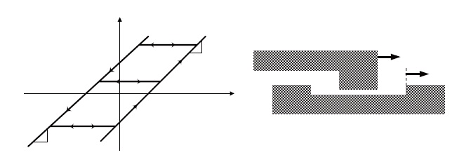
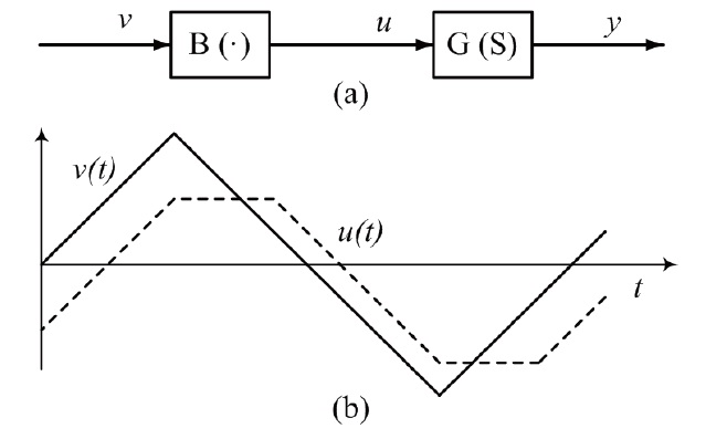
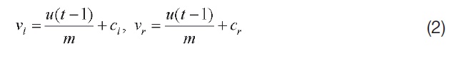
In contrast to the memoryless dead-zone, backlash has an element of memory and is dynamic. A widely accepted characteristic of backlash is shown Fig. 1, where
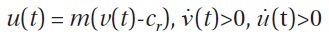
The upward side is active when both
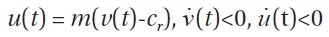
The downward side is active when both
where

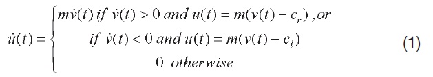
A compact description of the continuous-time version of the backlash
The discrete-time version of the backlash model is also easy to visualize, as shown below:
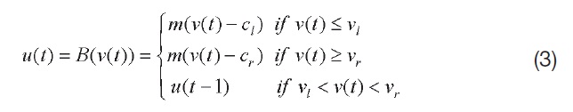
where the values
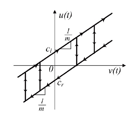
A further insight into the nature of backlash can be gained from the waveform of the output
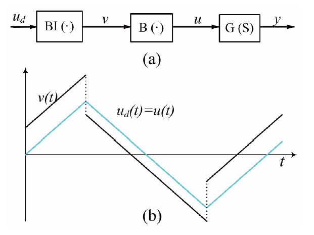
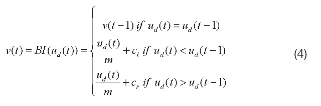
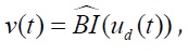
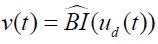
The desired function of a backlash inverse is to cancle the harmful effects of backlash on system performance. The ideal backlash inverse
backlash effect, as shown in Fig. 3. That is, given a desired signal
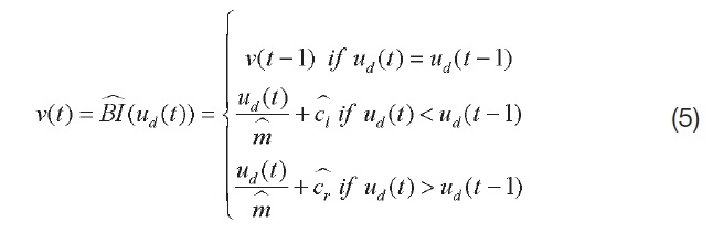
The discrete-time model of the backlash inverse is represented by the following mapping:
In this paper, the continuous-time version of the backlash inverse model is not shown. This is because the discretetime version has the following advantages. The discrete-time backlash inverse does not require knowledge of
for implementation. This makes a discrete-time adaptive inverse controller more practical than a continuoustime adaptive controller, because such signal derivative knowledge is often unavailable in applications. In addition, modern control systems are most frequently implemented with digital controllers so that a discrete-time treatment is closer to actual practice (Tao and Kokotovic, 1996).
The backlash inverse

to design a backlash inverse estimate:
characterized by
In the next section, we use an adaptive backlash inverse
3. Adaptive Backlash Inverse Control
3.1 Discrete-time adaptive Backlash inverse
In this section, the adaptive backlash inverse control structure and the applied adaptive law are presented. The goal of this section is to design a discrete-time adaptive backlash inverse controller to achieve asymptotic tracking, despite the presence of backlash.
Let us consider a plant whose linear part is

In the absence of backlash, our design objective to stabilize the closed loop system and make the plant output

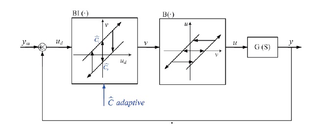
In the presence of backlash we use this controller along with an adaptive scheme designed to update the backlash inverse
on-line, as shown in Fig. 5.
Since, by assumption, m is known and

and

and introduce:

As such, the backlash inverse error equation becomes:

where
is the regressor.
For the tracking error,

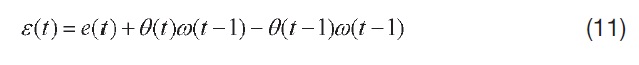
An important quantity for use in the discrete-time adaptive law is the estimation error, defined as:
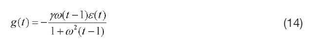
Using Eq. (11), our update law for θ(
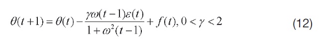
where
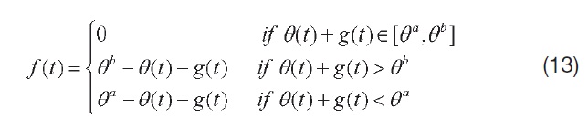
with the constants θ
A detailed proof of this is given by Tao and Kokotovic(Tao and Kokotovic, 1996), along with the stability and tracking properties of the closed loop system.
It can be seen that some aircraft experience limit cycle oscillations (LCOs) related to actuator nonlinearities (Mattos, 2008; Ross et al., 1979). This LCO of aircraft limits the performance of feedback systems and degrades aircraft handling qualities. Therefore, it can be seen as advantageous to eliminate such oscillations. One of the actuator nonlinearities, backlash, can also induce limit cycles and instability (Slotine and Li, 1991). According to Mattos (Mattos, 2008) the adaptive controller is designed to eliminate small amplitude, self induced oscillations due to actuator nonlinearities of Russian Su-37 aircraft.
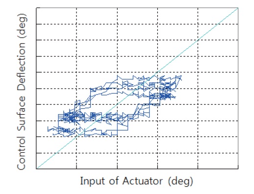
This section presents the numerical example of the aircraft showing limit cycles and actuator nonlinearity in flight in order to show the effectiveness of the proposed adaptive backlash algorithms. Figure 6 shows the I/O of the actuator, which is the relation between control command and the deflection of control surface based on the flight data.
The backlash characteristics of the aircraft shown in Fig. 6 are similar to those shown in Fig. 1. These characteristics
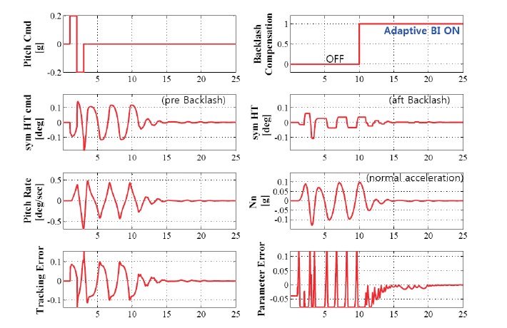
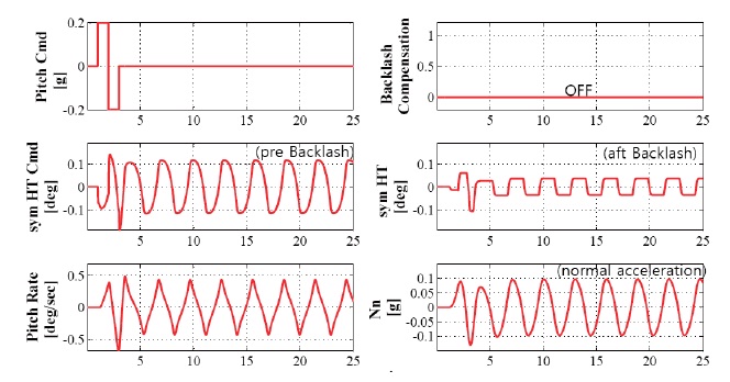
appear only in the specific aircraft and limited flight envelope as a form of LCO. The magnitudes and flight conditions are intentionally not included. We insert the backlash model in the horizontal tail actuator of the linear longitudinal model in order to compare the flight data and review the possibility of adaptive backlash compensation. Figure 7 shows the aircraft response when backlash is applied. The parameters of unknown backlash
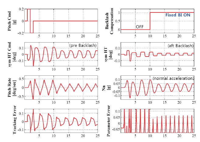
In order to eliminate the above harmful effects of backlash, we first apply the backlash inverse to the fixed type, not the adaptive type. This is because the signal, which is needed for the error equation for adaptive control from the aft backlash, cannot be used directly in a real aircraft control system.
The detailed parameters of the fixed backlash inverse are as follows,
To eliminate the effects of backlash model error and the variances from aircrafts and time, we apply the adaptive backlash inverse algorithm presented in Section 3. The constant gain,
It can be seen from the adaptive inverse examples that the backlash inverse parameters approximately reach the same values of the backlash parameters, once the diff erence between them converge to zero.
The characteristic of backlash, the mathematical model, and the backlash inducing LCO mechanism are presented in this paper. Feasibility is shown by comparison with flight data. A discrete-time adaptive backlash inverse based controller is developed for an aircraft that has an unknown backlash at its input. We verify through simulations that the backlash inverse parameter values reach the backlash parameter values in a short time interval. This means that an adaptive inverse can cancel the effect of an unknown nonlinearity, and thus improve system tracking performance.
As a future project, we intend to augment the adaptive state
feedback control based on neural networks to the actuator nonlinearities of an aircraft. This approach is expected to be flexible with regard to various actuator nonlinearities.