KC-100 is a prop single-engine civil aircraft that was developed to obtain a type certificate KAS(Korean Airworthiness Standards) Part 23 from KCACC (Korea Civil Aviation Certification Center). According to the KAS part23, newly developed general light aviation airplane should recover from the spin.
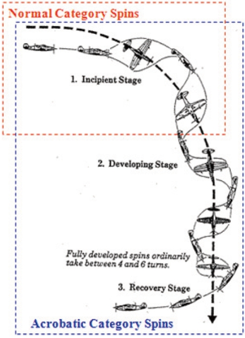
The spin maneuver is divided into three stages as depicted in Fig.1 - incipient spin, developed spin, and spin recovery. During the incipient spin stage, deliberate spin is initiated by slowing the airplane speed in order to increase the yawing motion. Incipient spin is the transition between the departure and the developed spin. In this phase, aircraft flight path is changed from horizontal to vertical, and the angle-of-attack of aircraft is increased. This results in the fall in the deep spin. In a steady, developed spin, aerodynamic and inertia forces come into balance. Yaw, roll, pitch rates, as well as angle-of-attack, descent rate, pitch rate are set to a steady value. In this stage, it is difficult to solve the dynamics of the steady spin due to the complexity of the aerodynamic forces. Fully developed spin is primarily due to the yawing motion. In the spin recovery stage, the applications of an anti-spin yawing moment are necessary to recovery from the aircraft spin. Even though KC-100 is designed to recover from a spin condition, emergent spin recovery device should be equipped in the aspect of safety. Prior to the discussion of KC-100 SRPS design, analytical and experimental spin prediction methods are briefly introduced below. In October 1926, Gates and Bryant performed a survey on the “Spinning of Aeroplanes”. Here, the equations that were required for calculating the equilibrium spins were described. Irving and Batson performed a continuous rotation balance in a wind tunnel. This test was performed between 1925 and 1935 and this provided aerodynamic coefficient data and also a good insight into aircraft spinning. The capability to calculate steady spin conditions from rotary balance data was revived by Dr. Bazzochi in 1975. Waye performed a flight test to study
the opening forces of a 9m diameter Ribbon parachute by which 344kg payload was recovered [1].
This paper deals with spin theory, the design of SRPS and the inspection procedures that are as shown in Fig.2. This paper also discusses on the results of deployment and jettison of SRPS on the high speed taxiing test.
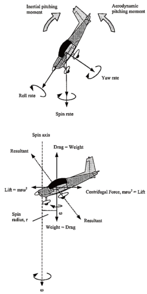
Understanding the basic principles of spinning is essential in the stage of developing a new aircraft from a preliminary design to detailed design, and flight test. Moreover, consideration of steady spin stage is important as it implies a stable equilibrium flight condition from which the recovery may be impossible. So, the theoretical approach usually begins from the equations of motion for quasi-steady state spin conditions. Equation of motion is described as follows and it is assumed that the acceleration of the airplane does not exist. Drag is equal to weight, lift is equal to centrifugal
force, and the side forces are neglected.
Force equilibrium can be expressed as follows,


Moment equilibrium can be expressed as follows,


Angular velocities of pitch, roll, yaw are functions of the spin rate and angular velocity ω at spin axis. Fig.3 shows the equilibrium of the steady motion state.
Airplane has an angle of attack α, side slip angle β. σ means flight path angle about the spin axis.
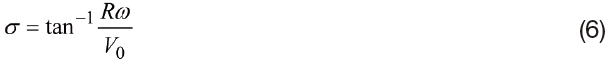
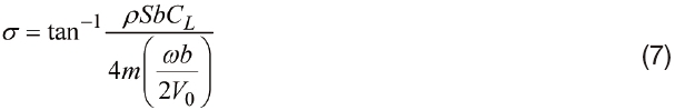
By substituting eq.(2) into eq.(6), σ can be expressed as eq.(7). Moreover, p,q,r represent the angular velocities of pitch, roll, and yaw. They can be summarized as eq.(8)~(10).


By substituting eq.(8)~(10) into eq.(3)~(5), each aerodynamic derivatives Cl,Cm,Cn can be obtained as follows,
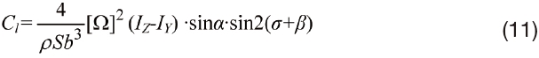
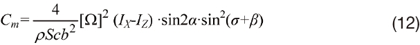
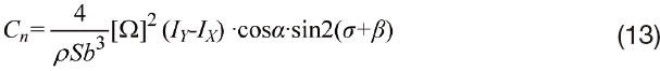
Where, Ω is dimensionless spin rate, S is wing area of the airplane, b is span length, c is mean aerodynamic chord(MAC) and IX, IY, IZ is the moment of inertia about each axis.

3.1.1 Forebody wake effects
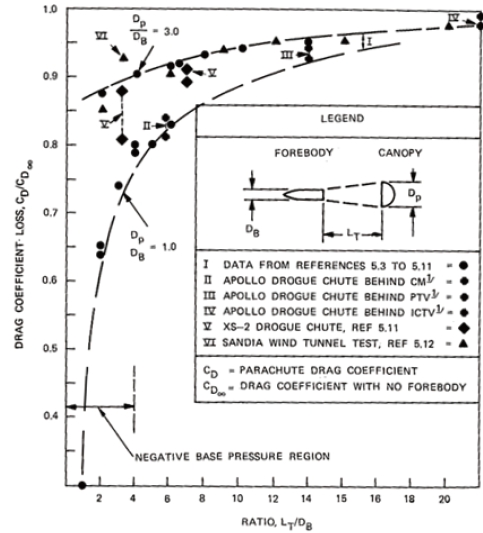
As the parachutes are deployed, airplane experiences a non-linear aerodynamic flow inter-relationship between the forebody and the parachute. This interaction of the flow disturbance by the forebody and the parachute is referred as the forebody effects. These effects are a function of the ratio DP/DB, LT/DB. If these parameters are small then, the parachute produces considerable wake effects. Moreover, deploying the small parachute in a large forebody causes considerable loss in the parachute drag and this may affect the stability of parachute. DB, DP is diameter of the forebody, parachute, respectively and LT is the relative distance between the forebody and the parachute. Fig.4 shows the drag effects according to DP/DB, LT/DB.
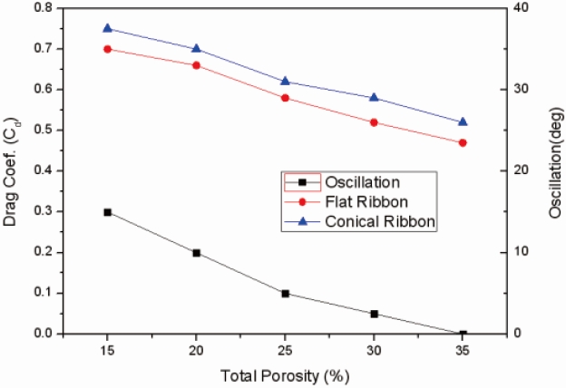
3.1.2 Porosity effects
Porosity is related to the parachute drag, stability, and opening force. Parachute drag, opening force, and oscillation decrease with an increase in the porosity as ahown in Fig.5. Decrease in the osicllation and opening forces is desirable, but decrease in the drag is undesirable.
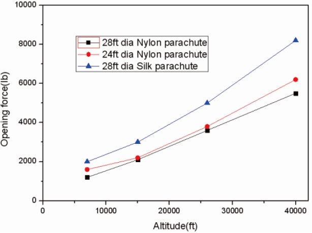
3.1.3 Altitude effects
According to the U.S. Army Air Corps, the Parachute opening forces at 40,000ft are about 4 times greater than the forces that are measured at 7000ft. This is despite the inflation of parachute at the same dynamic pressure. Moreover, nylon parachute has considerably lower opening forces compared to the silk parachute. This is as shown in Fig.6 and it may be due to the difference in the elongation between the nylon and silk.
3.1.4 Aeroelasticity effects
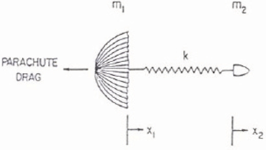
Airplane in connection with the parachute is simplified as shown in Fig.7.
Equation of motion is described as follows,


Suppose,
1. Gravity is neglected as it acts uniformly on the system.
2. Forebody drag is negligible compared to the parachute.
3. Internal viscous damping is ignored.
4. Dynamic pressure is constant throughout the inflation.
Eq.(15)-(16) can be combined to eq.(17)

where,
f (t/tF)=CDS/CD0S0 : non-dimensional drag area
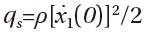
: dynamic pressure at initial inflation
ω=(k/m2+k/m1)1/2 : natural frequency
ξ=(x2-x1)
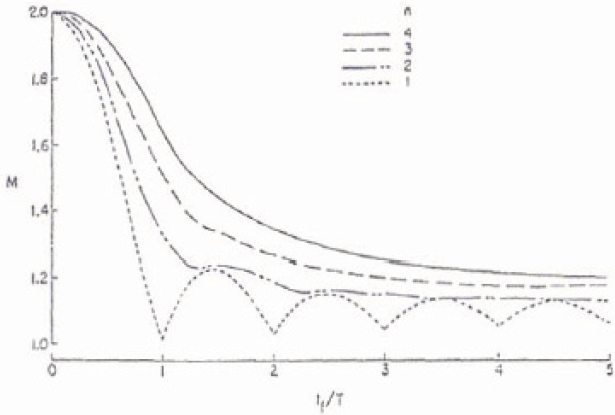
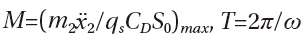
Fig.8 shows the solution of eq.(17) that is calculated by using the Duhamel’s integral. It shows plots of load factor M, versus the ratio of the filling time to the natural system period(tF/T). Decrease in the filling time tF, and increase in the system period T, results in the increase of maximum opening forces. The ratio between the maximum opening forces against the product of the maximum drag area and dynamic pressure is commonly referred to as the opening load factor. It is directly related to the aeroelastic properties.
where,
The inflation shape of a parachute canopy depends on the type and geometric design of a canopy (flat, conical,
triconical, hemispherical). It also depends on the canopy porosity, and on the suspension-line length.
Operation conditions of SRPS are determined as follows.
λ MTOW : 3600(lb)
λ Rate of descent : 183.94(ft/sec)
λ Deployment altitude : 8000(ft)
3.2.1 Parachute type
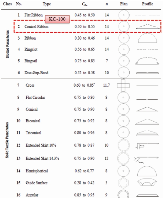
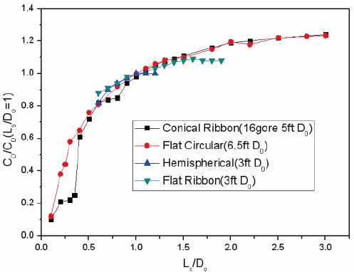
Although slotted parachute generally has a lower drag coefficient compared to the solid textile parachute, it has excellent stability during deployment. In the case of KC-100 SRPS, conical ribbon canopy has been selected. It has been selected due to it’s superior stability, low opening force, and high drag coefficient as shown in Fig.9.
3.2.2 Parachute sizing
Determination of the correct parachute size and riser length is important in the design of SRPS. Riser legnth controls the position of the parachute in the wake of the spinning airplane. This affects the force that the parachute can apply to the airplane. Experimental spin tunnel tests should be conducted in order to determine the parachute diameter and riser length, but KAI refers to the experimental data that is obtained from KTX-1 spin test. This is conducted by the Agency for Defense Development(ADD) due to the limitation of budgets.
Eq.18 is an experimental equation to determine the parachute diameter.

where,
CD : drag coefficient, A : parachute area, S : wing area, b : wing span, L : length between CG and parachute connecting point
Drag coefficient that is used in the parachute design is 0.55. Parachute area can be calculated based on eq.18. Compared to parachute area of KT-1(Korean Trainer), KC- 100 parachute area is 1.3 times larger than that of KT-1. And riser length ratio(
3.2.3 Parachute porosity
There are many advantages in the aspect of airplane stability with an increasing porosity. However, parachute canopy may not open at all as its critical opening speed will be too low, if the parachute has too high porosity. Based on the parachute test results of Airbornes systems, a total porosity of 35% is selected.
[Table 1.] Parachute design factor
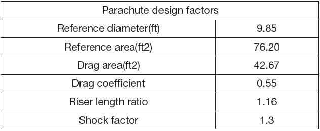
Parachute design factor
4.1.1 Stay voltage check
Connectors should be disconnected to check stray voltage. A/C ground, and pyro related pin continuity are the prerequisites. Table 2 shows the pin assignment that is related to deployment and jettison.
4.1.2 Measurement test setup
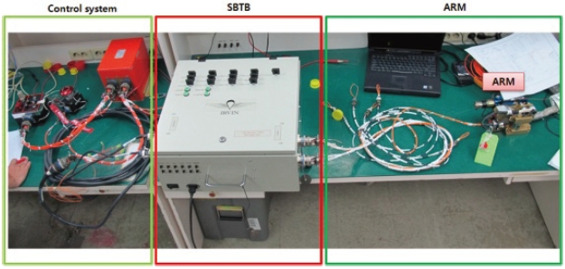
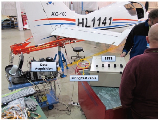
Integrated lab test is required to ensure the function of SRPS. Airborne System Break-out Test Box (SBTB) is used to
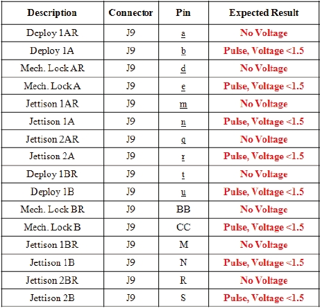
SRC pin assignment
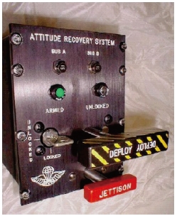
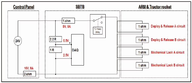
validate a normal operation, and the parachute firing of SRPS is as shown in Fig.11. It consists of a control panel, deploy switch, control electronic module, SBTB and ARM(Attach Release Mechanism). Control system supplies power, and it checks the data status. SBTB simulates the firing of the pyrotechnic devices that are being installed on a tractor rocket and ARM. ARM functions locks the features in order to fix the parachute. Tractor rocket is used to help in the deployment of a parachute without reaction force. As shown in Fig.12, Circuits of SBTB consists of data acquisition part, pyro current measuring part. Resistors that are connected to DAQ are large enough compared to that of pyro. So, the test circuit can be simplified as a serial circuit of control panel and SBTB.
4.1.3 Lab test results
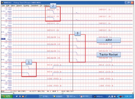
Operating sequences should proceed in the following order ? pyro mechanical lock, deployment, and release. Fig.13 shows the simulated firing signal that is measured in the SBTB.
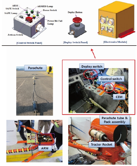
SRPS consists of a parachute, deployment button, cockpit control system, Attach Release Mechanism (ARM), tractor rocket, and parachute tube & pack assembly. SRC control panel of T-50 is shown in Fig.14 and it contains a power switch, light to check either safe or arm state, deployment, and jettison lever. Those of KC-100 are divided into three components namely; control panel, deployment switch, and electronics module unlike T-50. Both KC-100 and T-50 use the same ARM that contains 1 pyro-lock initiator, 2 cutter initiators to cut and lock the parachute. And tractor rocket is used to deploy the parachute unlike the mortar system of
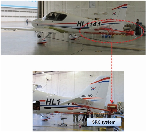
T-50, F-16 combat aircrafts. The tractor rocket is suited for small aircrafts as there are less reaction forces that influence the aircrafts compared to the mortar system. Parachute pack assembly contains a parachute canopy, riser, and deployment bag. Parachute and riser are contained within an extraction tube. The ribbon-type parachute that is robust and damagetolerant is used in SRPS. It will be mounted externally on the aircraft. Parahute system will be initiated from the DEPLOY command. Fig.15 shows the components of SRPS of KC-100. Fig.16 shows the aircraft installation configuration of the SRC.
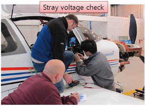
5.2.1 Stray voltage check
Prior to the operation of SRPS, SRC connectors that are installed in the aircraft should be validated. As shown in Fig.17, stray voltages, continuity checks of wires that are related to deployment, mechanical lock and jettison should be performed.
5.2.2 Normal operation test
Confirm if the lights of a control panel are flashing. After the PBIT(Periodic Built In Test) check which implies the validation of power quality, mechanical lock position, pyrotechnic related circuits that correspond to the light should be on either in the safe or arm position.
5.2.3 Firing sequence test
The purpose of this test is to validate the sequence and current at the instance of firing a rocket and the pyrotechnic devices are being installed on ARM. In order to simulate it, the red cables between the aircraft and SBTB should be connected. If on deployment, jettison buttons are pressed when black cables are connected then, explosion of rocket will occur. Unlike the lab firing test, when black cables are connected to the aircraft, fault may occur as the requirements of mechanical lock and deployment & release resistance should be respectively below 2.5Ω, 3.8Ω. In this case, it is reasonable to substitute the resistor position onto the bypass position on the SBTB. But once red cables are connected to perform the firing sequence test, keep in mind that plug position have to convert bypass into resistor position.
Otherwise SBTB may be damaged. Fig.18 shows the SRC test setup. Table 3 shows the firing sequence test results. SD Amps, time, OR Amps represent Step-down current(Amp), time delay(msec) respectively. In a normal operation, minimum 4amp SD current, and above 10msec time delay should be measured. Therfore, as shown in Table 3, the firing sequence tests are well performed.
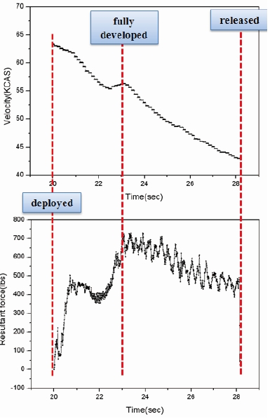
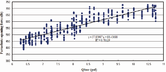
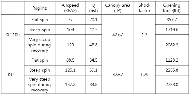
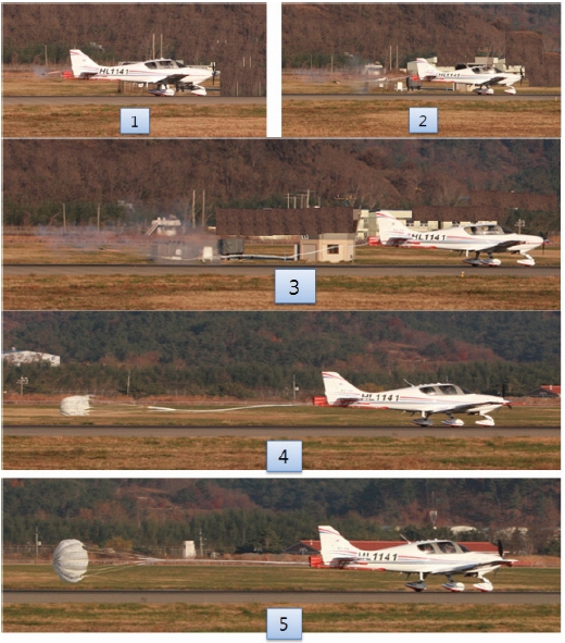
Before the deployment of SRPS in a critical spin/stall conditions, it should be carefully deployed and released on the HST(High Speed Taxiing) in order to validate the structural integrity, reliability, and susceptibility. Deployment test on HST for KC-100 is proceeded at a decreasing velocity condition with respect to safety. Fig.19 shows the measurement results of velocity, parachute opening force at the instant of deployment and jettison. Fig.20 shows the linear regression of a parachute opening force. Even though the test is performed in the ground, opening forces of parachute can be estimated when the aircraft fell into a spin mode. Table 4 shows the opening forces when the parachute is deployed in a spin mode. When considering the trends of the deployment test results, opening forces of KC-100 are
[Table 3.] Firing sequence test results
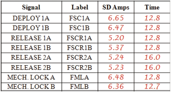
Firing sequence test results
similar to those of KT-1. Fig.21 shows the still pictures during the deployment test.
Based on the taxiing test results, opening forces in the spin state are obtained as described in Table 4. In order to reduce the reaction forces, the canopy is designed large compared to KT-1. Moreover, the conservative load related design factors are used in considering the uncertainties of spin conditions.
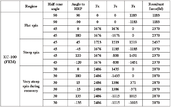
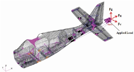
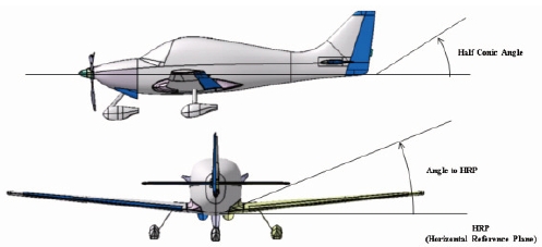
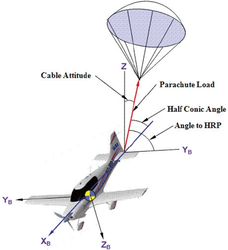
FEM analysis of SRPS in spin conditions is also performed to validate the test results. Fig.22 shows the finite element model that is used for spin recovery assembly structures. Table 5 shows the resultant opening forces that are calculated in each spin stage. Compared to the FEM analysis with test results, the test results seem to be as reasonable results. Fig.23 shows the definition of a half cone angle and angle to HRP(Horizontal Reference Plane).
SRPS of KC-100 is designed and tested on HST(High Speed Taxiing) in order to obtain a type certificate of KAS(Korean Airworthiness Standard) Part23 from the KCACC. Prior to the detailed design, researches on the major aerodynamic, structural factors that influence the spin recovery system are performed. Moreover, FEM analysis is conducted to validate the SRPS structural limit. Before the deployment test on HST, lab test and operation check are carefully done. Even though the parachute system is not deployed in an emergency spin
[Table 4.] Estimated opening force results in spin state compared to KT-1

Estimated opening force results in spin state compared to KT-1
state, deployment and jettison of parachute on HST are successfully performed. By conducting linear regression of taxiing test results, opening forces in each spin conditions are estimated. Based on these results, it is considered that SRPS are well designed.
[Table 5.] FEM analysis results

FEM analysis results


![Equilibrium of steady spin motion [1]](http://oak.go.kr/repository/journal/11316/HGJHC0_2012_v13n1_117_f003.jpg)
![Parachute drag loss caused by forebody wake [2]](http://oak.go.kr/repository/journal/11316/HGJHC0_2012_v13n1_117_f004.jpg)
![Drag coefficient & oscillation as a function of total porosity [2]](http://oak.go.kr/repository/journal/11316/HGJHC0_2012_v13n1_117_f005.jpg)
![Opening forces as a function of parachute materials, altitude [2]](http://oak.go.kr/repository/journal/11316/HGJHC0_2012_v13n1_117_f006.jpg)
![Load factor as a function of filling time, system period [3]](http://oak.go.kr/repository/journal/11316/HGJHC0_2012_v13n1_117_f008.jpg)
![Parachute canopy type [2]](http://oak.go.kr/repository/journal/11316/HGJHC0_2012_v13n1_117_f009.jpg)
![Parachute suspension line length [2]](http://oak.go.kr/repository/journal/11316/HGJHC0_2012_v13n1_117_f010.jpg)