Flutter is one of the most important aeroelastic phenomena. Flutter can occur to a structure in a flow field, and it consists of undamped vibrations that can lead to catastrophic collapses. This implies that flight vehicles or bridges, for instance, must be clear of flutter. Different analysis tools have been developed over the last decades to predict flutter. A vast range of aerodynamic models have been utilized in aeroelastic problems, from strip theories to Reynolds-averaged Navier-Stokes (RANS). Excellent reviews about these methodologies are presented in [1] and [2]. One of the first methods for flutter analysis was strip theory [3-4]. From the early 1940s to the 1960s, strip theory and its variations represented the most important tools for flutter. The doublet lattice method (DLM) emerged in the late 1960s [5]. More recently, an improved version of DLM has been proposed by Rodden [6], and it is this version that is utilized in this work. To date, DLM is one of the most powerful tools for linear flutter analyses in the subsonic regime. Three main features are responsible for DLM’s success [1]:
1. It offers good accuracy (unless transonic regimes are considered and/or separation occurs).
2. DLM is cost competitive with respect to simpler methods such as strip theories.
3. Fairly complex geometries can be analyzed.
The structural component of the aeroelastic formulation adopted in this paper was based on 1D higher-order structural models commonly known as beams. Beam theories are extensively used to analyze the structural behavior of slender bodies, such as columns, arches, blades, aircraft wings and bridges. In a beam model, the 3D problem is reduced to a set of variables that only depends on the beam-axis coordinate. One-dimensional structural elements are simpler and computationally more efficient than 2D (plate/shell) and 3D (solid) elements. This feature makes beam theories still very attractive for the static, dynamic and aeroelastic analysis of structures.
The classical theories are those by Euler-Bernoulli [7-8] and Timoshenko [9]. None of these theories can detect non-classical effects such as warping, out- and in-plane deformations, torsion-bending coupling or localized boundary conditions (geometrical or mechanical). These effects are important when, for instance, small slenderness ratios, thin walls and the anisotropy of the materials are considered. An accurate aeroelastic analysis requires the proper detection of non-classical effects.
Many methods have been proposed to overcome the limitations of classical theories and to extend the application of 1D models to any geometry or boundary conditions [10]. Most recent developments in 1D models have been obtained by means of the following approaches:
1. The introduction of shear correction factors.
2. The use of warping functions based on the de Saint-Venant solution.
3. The variational asymptotic solution (VABS).
4. Generalized beam theories (GBT).
5. Higher-order beam models.
A considerable amount of work has been done to try to improve the global response of classical beam theories through the use of appropriate shear correction factors, as in the books by Timoshenko [11] and Sokolnikoff [12]. Many interesting articles [13-17] have been published on this topic.
El Fatmi [18] introduced improvements of the displacement models over the beam section by introducing a warping function to enhance the description of the normal and shear stress of the beam. End effects due to boundary conditions have been investigated by means of this model [19].
The de Saint-Venant solution has been the theoretical framework of many advanced beam models. 3D elasticity equations were reduced to beam-like structures [20]. The resulting solution was modeled as the sum of a de Saint-Venant part and a residual part, and applied to high-aspect-ratio beams with thin-walled sections. Other beam theories have been based on the displacement field proposed [21] and solved by means of semi-analytical finite elements as in [22].
Asymptotic-type expansions have been proposed in [23] on the basis of variational methods. That work represented the starting point of an alternative approach to constructing refined beam theories where a characteristic parameter (e.g. the cross-sectional thickness of a beam) is exploited to build an asymptotic series. Those terms that exhibit the same order of magnitude as the parameter when it vanishes are retained. Some valuable contributions on asymptotic methods are those related to VABS [24-26]. The key feature of this methodology is that the 1D model is governed by variationally consistent and geometrically exact governing equations which provide asymptotically exact stress and strain recovery by means of a beam model having a low number of degrees of freedom. Regular and thin-walled beams can be accounted for.
Generalized beam theories (GBT) have been derived from Schardt’s work [27]. GBT enhances classical theories by exploiting piece-wise beam descriptions of thin-walled sections. It has been extensively employed and extended in various forms [28]. In the GBT framework, the cross-section displacement field of a thin-walled beam is assumed as a linear combination of deformation modes defined on a number of cross-section nodes. The proper choice of the number of modes depends on the cross-section type and the number of fold lines [29].
Many other higher-order theories which are based on enhanced displacement fields over the beam cross-section have been introduced to include non-classical effects. Some considerations on higher order beam theories were made by Washizu [30]. An advanced model was proposed in [31] where classical finite beam elements were improved by introducing new degrees of freedom to describe the cross-section behavior. Other refined beam models can be found in the excellent reviews by Kapania and Raciti [32-33], which focused on: bending, vibration, wave propagations, buckling and post-buckling. Excellent papers on structural dynamic and aeroelastic problems of thin-walled structures by means of higher-order beams are those by Librescu [34-36].
The aim of this work is to present aeroelastic models based on highly accurate structural models and low-order aerodynamic tools. Particular attention was given to the flutter of wings and thin-walled panels. The adoption of the present formulation allows one to predict flutter with remarkable reductions of computational costs and acceptable accuracy.
This work is embedded in the framework of the Carrera Unified Formulation (CUF) for higher-order 1D models [37]. CUF had been initially developed for plates and shells [38-39], and more recently for beams [40-41]. The unique contribution given by CUF models is due to their hierarchical capabilities which make the choice of the expansion functions (F
Static [41-43], free-vibration [44-46] and buckling [47-48] analyses have shown the enhanced capabilities of CUF 1D models, which are able to detect shell- and solid-like solutions for different structural models, including thin-walled models under point loads and shell-like natural modes. A further extension of the present formulation [49-51] dealt with open cross-sections, boundary conditions enforced on lateral edges and component-wise approaches.
Varello et al. [52] extended CUF 1D to steady aeroelasticity by using the Vortex Lattice Method (VLM). In this work, unsteady aeroelasticity is considered through the Doublet Lattice Method (DLM). CUF was exploited to derive structural refined finite 1D elements; that is, the structural component of the proposed advanced aeroelastic formulation was based on 1D CUF higher-order models. This paper is organized as follows: first, the structural and aeroelastic formulations are briefly described; afterwards, results and their discussion are presented; eventually, main conclusions are drawn.
2. Structural Formulation: CUF 1D Models
The unified formulation of the beam cross-section displacement field is described by an expansion of generic functions,

where
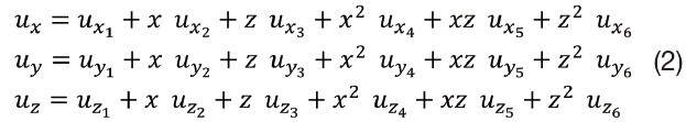
The 1D model described by Eq. 2 has 18 generalized displacement variables: three constant, six linear, and nine parabolic terms.
The governing equations were derived by means of the Principle of Virtual Displacements (PVD). Starting from the unified form of the displacement field in Eq. 1, stiffness, mass, and loading arrays can be obtained in terms of fundamental nuclei whose form is independent of the order of the model. The finite element method (FEM) was adopted to overcome the limits of analytical solutions in terms of geometry, loading, and boundary conditions. The displacement variables are interpolated along the axis of the beam by means of the shape functions,

where q
According to the principle of virtual displacements,

where

where
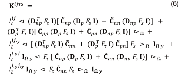
where

is the material coefficient matrix and D is the differential operator matrix. For the sake of brevity, their expressions are not reported here, but they can be found in [37]. The following about the formal expression of
1. That it does not depend on the expansion order,
2. Nor does it depend on the choice of the Fτ expansion polynomials.
These are key points of CUF which permit the implementation of any order of multiple class theories, with only nine FORTRAN statements.
The virtual variation of the work of inertial loadings is

where

where
The undamped dynamic problem can be written as follows:

where

where φ
3. Aeroelastic Formulation: Doublet Lattice Method and Mesh-to-Mesh Transformations
Following Landahl [53] or Albano [5], the normalwash at a point with coordinates

in the point

where

The kernel function (

where
The unsteady aeroelastic analysis was carried out by considering a set of modal shapes as generalized motions for the unsteady aerodynamic generalized force generation. Each set of modal shapes,


where

and

where all the vector quantities have to be understood as vectors of amplitudes of the harmonic motion, and
4. Generalized Matrices and G-Method
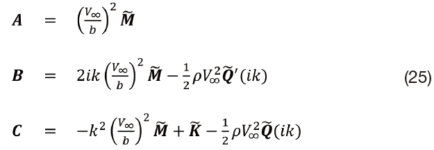
The generalized aerodynamic matrix for a given reduced frequency (

where:
k = ωb/L, b is the reference length (equal to the half of the reference chord) and L is the length of the structure.
is the pressure jump due to the j-th set of motions (modal shapes), acting on the N-th aerodynamic panel and evaluated for a given reduced frequency. The computation of the pressure jump is performed by means of the DLM.

is the i-th motion set evaluated at the N-th aerodynamic panel. Starting from the i-th modal shape given by a structural model, the i-th motion set is then mapped on the aerodynamic panels by means of the splining process. In this work, modal shapes were evaluated by means of CUF 1D models.
AN is the area of the N-th panel.
Q(ik) is a square matrix with Nmodes × Nmodes elements, where Nmodes indicates the total number of natural modes adopted. Typically, Nmodes ranges from 10 to 20.
The generalized mass matrix is given by

where:
φ is a matrix containing a given number of modal shapes, dimension: NDOF × Nmodes. NDOF is the total number of DOFs of the structural model.
M is the mass matrix of the structure (dimension: NDOF × NDOF), M is a square diagonal matrix with Nmodes × Nmodes terms.
The generalized stiffness matrix is a square diagonal (Nmodes × Nmodes) matrix, and its diagonal terms are given by

where
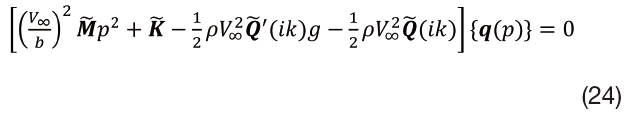
The g-method was introduced by Chen [57] and it is based on a damping perturbation technique and a first-order model of the damping term. Its derivation exploits the aerodynamics in the Laplace domain and can be found in [57]. The basic assumption of the g-method is based on the following approximation of the generalized aerodynamic matrix:

where
Where
The generalized aerodynamic matrix,

is provided by the unsteady aerodynamic model (DLM) in the frequency domain. The computation of

has to be performed numerically. A central difference scheme can be used. with a forward scheme at
Eq. 24 becomes

This is a second-order linear system in

where

A so-called reduced-frequency-sweep technique is adopted to find the solution having Im(
a range of k values is chosen, [0, kmax], with kmax as the highest value in the reduced frequency list of the unsteady aerodynamic computation;
a step Δk is fixed;
at each step i the eigenvalues of D are computed for ki = ki?1 + Δk;
a sign change of the imaginary part of each eigenvalue is searched for;
if a sign change occurs and Re(g) > 0, the reduced flutter frequency will be computed by means of a linear interpolation.
Numerical examples are presented and discussed in this section. After a preliminary aerodynamic assessment, flutter analyses were carried out for the following structural configurations:
1. Single- and double-swept wings.
2. A panel with the leading edge clamped.
Results from open literature and experiments were exploited for comparison purposes. All results were obtained in the case of incompressible flow (
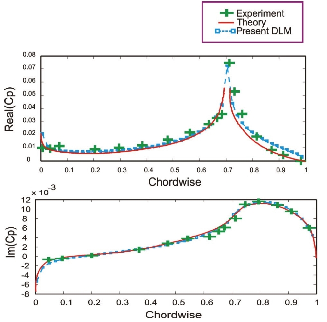
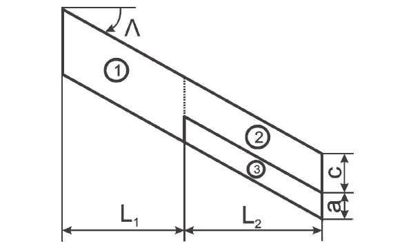
A wing with oscillating outer flaps is considered in this section. This model was retrieved from [58] and its geometry
is shown in Fig. 1 (only half wing is shown), where:
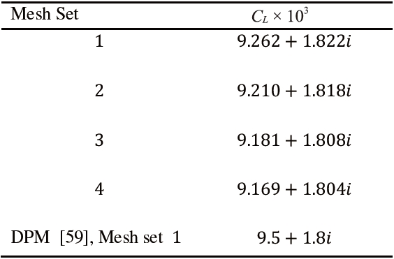
Table 2 presents lift coefficients,
Flutter analyses of swept wings were considered in this
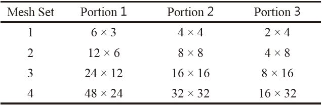
[Table 1.] Mesh sets adopted for the wing model with oscillating flaps

Mesh sets adopted for the wing model with oscillating flaps
[Table 2.] CL coefficient for different mesh sets

CL coefficient for different mesh sets
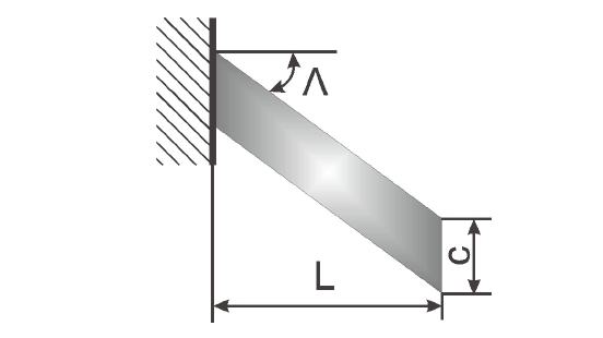
section. The swept wing model was retrieved from [61] where plate models based on the Classical Laminated Theory (CLT) were used for flutter analyses. The wing model investigated has the following characteristics (see Fig. 3):
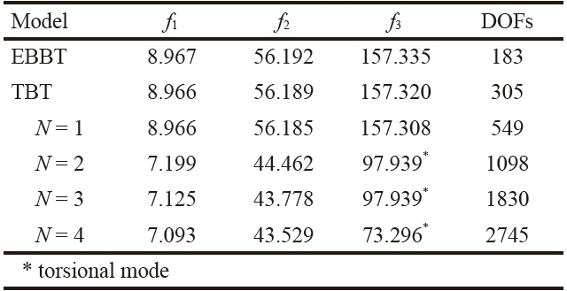
Table 3 presents the first three natural frequencies of a backward swept configuration. Unless otherwise indicated, the frequencies reported are related to bending modes. The results from different 1D structural models are shown, including classical models (EBBT and TBT) The indication of the number of DOFs of each structural model is reported
[Table 3.] Effect of the CUF 1D expansion order (N) on vibration frequencies, Hz, Λ=30°, 20 B4 mesh

Effect of the CUF 1D expansion order (N) on vibration frequencies, Hz, Λ=30°, 20 B4 mesh
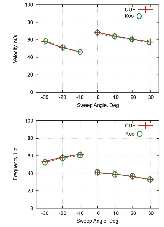
in the last column. Convergence studies are presented in Tables 4 and 5, where the effects of the structural mesh and the Taylor expansion order on flutter conditions are reported, respectively. The flutter conditions for different sweep angles are given in Table 6 and Fig. 4, where the results from the present formulation are compared with those by Koo [61]. The analysis of the results suggests the following:
1. Higher-order 1D models are mandatory in order to predict torsional modes and flutter conditions of wings.
2. The proper detection of torsional modes requires at least an N = 3 model, as also shown in [37].
3. For these wing configurations, the first torsional mode plays a fundamental role in flutter conditions. This means that the proper detection of flutter conditions requires at least a third-order 1D structural model (N = 3).
4. Flutter predictions by the present structural formulation (1D) are in excellent agreement with those by Koo (CLT, 2D).
[Table 4.] Effect of the structural mesh on flutter conditions, N=3, Λ=30°
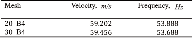
Effect of the structural mesh on flutter conditions, N=3, Λ=30°
5. Very low computational costs were required.
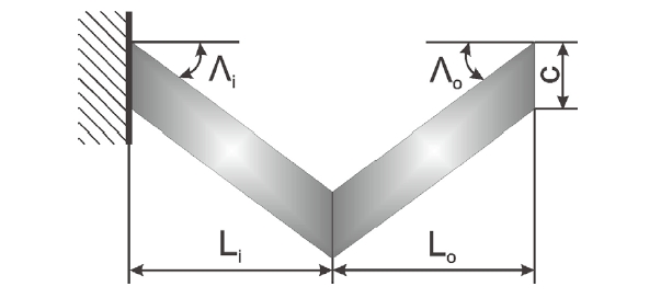
A double-swept wing was considered in this section. This model was retrieved from [61]. Wing characteristics are described in Fig. 5, and their values are the following:
20 B4 mesh was used for the structural discretization. These meshes were chosen via a convergence study.
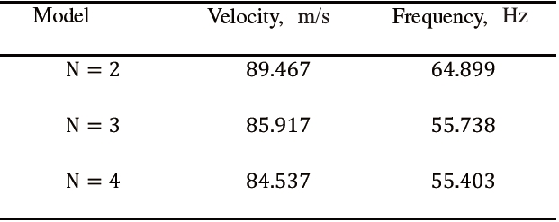
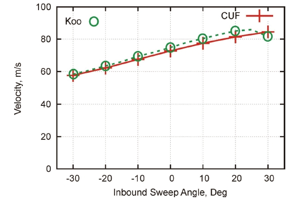
Table 7 shows the effect of the Taylor expansion order on flutter conditions for Λ
The following statements hold:
1. As previously shown for the single-swept configuration, at least an N - 3 model is required to compute flutter conditions.
2. Very good agreement was found with results based on plate models.
3. It can be concluded that the present 1D structural formulation can properly detect the flutter of double-
[Table 5.] Effect of the CUF 1D expansion order, N, on flutter conditions, 20 B4 mesh
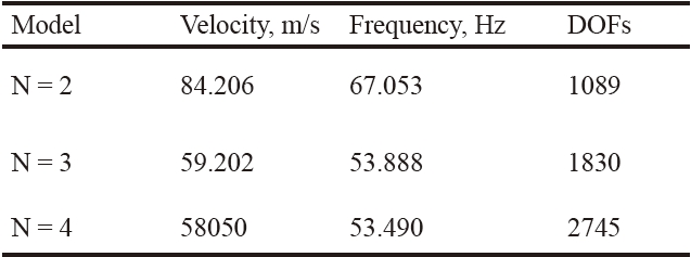
Effect of the CUF 1D expansion order, N, on flutter conditions, 20 B4 mesh
[Table 6.] Flutter conditions for different sweep angles, 20 B4 mesh, N=4
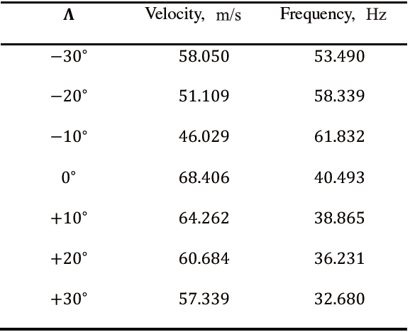
Flutter conditions for different sweep angles, 20 B4 mesh, N=4
[Table 7.] Effect of the expansion order on flutter conditions of the double swept wing, Λi = 30°

Effect of the expansion order on flutter conditions of the double swept wing, Λi = 30°
[Table 8.] Flutter conditions for different inbound sweep angles, N=4
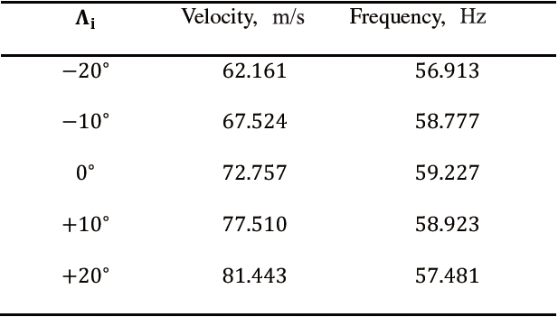
Flutter conditions for different inbound sweep angles, N=4
Effect of the CUF 1D expansion order, N, on vibration frequencies, Hz, flutter velocity, m/s, and flutter frequency, Hz, of the cantilever plate, 20 B4 mesh
swept wing models.
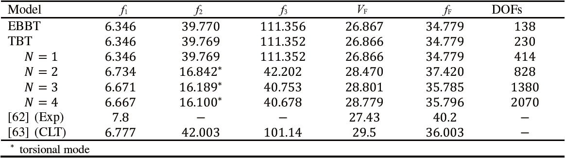
This section was focused on the flutter analysis of a square panel clamped along its leading edge and free on the other three edges. This model was retrieved from and [62]. [63] The plate has a thickness of 0.020 inches and a length of 10 inches. An isotropic material was adopted (
Table 9 shows natural frequencies and flutter conditions from different models and experimental results. Unless otherwise indicated, natural frequencies are related to bending modes. It is important to underline the following:
1. Lower-order models are able to quite accurately describe bending, whereas higher-order models are needed for torsion.
2. Since the second bending mode is involved in flutter, low-er-order models can predict the instability in this case.
3. Results from the present structural 1D formulation are in good agreement with those from experiments and CLT; larger differences with the experimental data were observed in the detection of the frequencies. However, it is important to emphasize that in [62], the calculated natural frequencies were also provided, and they were equal to 6.7 and 42 Hz, respectively. Calculated flutter frequencies were also provided, and depending on different aerodynamic models, they ranged between 37.5 and 42.6 Hz.
Flutter analyses of isotropic lifting surfaces have been carried out in this study. The aeroelastic formulation exploited in this work was based on 1D advanced structural models and the doublet lattice method. The aerodynamic and structural mesh coupling has been conducted through the infinite plate spline method. Flutter conditions have been computed via the g-method.
The advanced structural models have been developed in the framework of the Carrera Unified Formulation (CUF). CUF 1D models exploit Taylor-like polynomials to define the displacement field above the cross-section of the beam. Any-order structural models can be implemented since the order of the Taylor expansion is a free parameter of the formulation. This means that the order of the structural model can be set as an input, and convergence studies have to be carried out in order to establish the proper theory order necessary for a given problem.
The analyses conducted suggest the following:
1. Refined 1D structural models are mandatory for proper flutter analyses of lifting surfaces.
2. Refinements are needed to capture torsional modal shapes and to deal with thin walls.
3. The present 1D structural model is cost-competitive if compared to 2D plate models, with no accuracy losses.
The use of CUF 1D could offer even greater advantages in the fluid-structure-interaction analysis of flexible structures with highly deformable cross-section, such as adaptive wings or arteries. CUF 1D can, in fact, predict in-plane distortion of thin-walled structures with high accuracy and very low computational costs, as shown in [37]. Future works should deal with the coupling of CUF 1D with computational fluid dynamics tools.