A, G, Gd State and input matrices
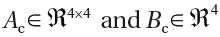
Ac, Bc State and input matrices of transformed system
A*c Matrix of the system zero dynamics
a∞, p∞, ρ∞ Sound speed ,the pressure and air density of the undisturbed flow respectively
B Non-linear restoring moment
C0, C1, C, C3 Constants used in the bounded neural network composite weight matrix
e, r Tracking error and filtered tracking error, respectively
F, G Positive definite diagonal gain matrixes for update laws of ? and V
g1, g2 Auxiliary saturation gains
Kz, Kv, Γ , Zb, Kd Controller gains
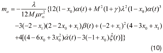
La(t), Ma(t) lifting and aerodynamic moment
p(y, t) Unsteady pressure
V Dimensionless flight speed
vz(t) Downwash velocity normal to the airfoil surface
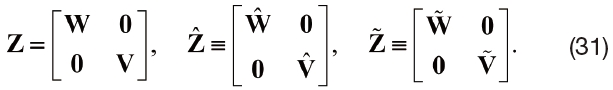
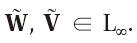
W, V Ideal neural network interconnection weight matrices

Estimated neural network interconnection weight matrices
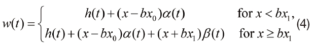
w(t) Transverse deflection
x, u System state and input, respectively
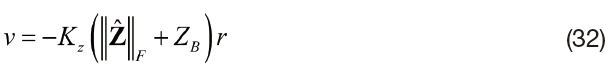
Z, ZB Ideal neural networks composite weight matrix and its bound

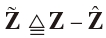
Estimated neural networks composite weight matrix and mismatch

Auxiliary control input
ξ Dimensionless plunging displacement ξ = h / b
γ Isentropic gas coefficient (γ = 1.4 for dryair)
τ Dimensionless time τ = Ut / b
λ Aerodynamic factor
η(t) Vector of system states for analysis of zero dynamics
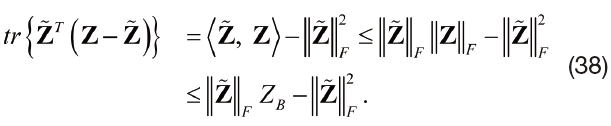
tr{? } Trace of a square matrix defined as the sum of the elements on the matrix main diagonal
||?||F Frobenius norm defined as ||A||F =
< A, B> Inner product of two matrix, defined as tr{B*A}
In recent years, aeroelastic control and flutter suppression of flexible wings have been extensively investigated by numerous researchers. There are two basic problems associated with the aeroelastic instability of lifting surfaces ? the determination of the flutter boundary and of its character,
A plethora of techniques is available for dealing with the effect of non-linear structural stiffness in the context of subsonic flow; linear control theory, feedback linearizing techniques, adaptive, and robust control techniques have been employed to account for these nonlinearities,
Motivated by our previous work in [19][21] and [23]-[25], a novel neural network (NN) based robust controller has been designed to asymptotically stabilize a supersonic aeroelastic system with unstructured nonlinear uncertainties. The nonlinearity of the model depends on the plunging distance and pitching angle. If the nonlinearity is known and could be linearly parameterized, then adaptive control is often considered to be the method of choice. In this paper, we assume unstructured uncertainty in the sense that the structure of the system nonlinearity is considered to be unknown. In contrast to existing neural network-based controllers that only achieve practical stability, the novel continuous control design in this paper is able to achieve asymptotic stability of the origin. A three-layer neural network is implemented to approximate the unknown nonlinearity of the system. While adaptive control relies on linear parameterizability of the system nonlinearity and the determination of a regression matrix, the universal approximation property of the NN controller enables approximation of the unstructured nonlinear system in a more suitable way. To compensate for the inevitable NN functional approximation error, an integral of a sliding mode term is introduced. Through a Lyapunov analysis, global asymptotic stability can be obtained for the tracking error in the pitching degree of freedom. Then, based on the fact that the system is minimum phase, the asymptotic stability of the plunging degree of freedom is also guaranteed. Simulation results show that this NN-based robust continuous control design can rapidly suppress the flutter and limit cycle oscillations of the aeroelastic system.
The rest of the paper is organized as follows. In Section II, the aeroelastic system dynamics are introduced. In Section III, the control objective is stated explicitly while zero dynamics of the system is analyzed. The open-loop error system is developed in Section IV to facilitate the subsequent control design while the closed-loop error system is developed in Section V. In Section VI, Lyapunov-based analysis of the stability of the closed-loop system is presented while the simulation results are shown in Section VII. Appropriate conclusions are drawn in Section VIII.
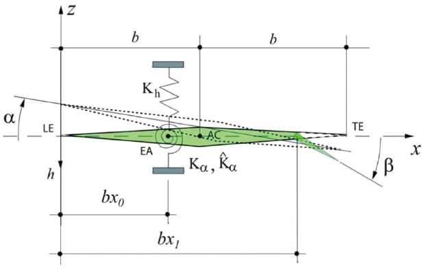
The aeroelastic governing equations of a supersonic wing section with plunging and twisting degrees-of-freedom (graphically represented in Fig. 1), accounting for flap deflections, and constrained by a linear translational spring and a non-linear torsional spring, are given as follows
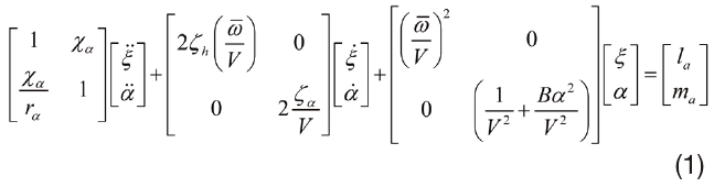
The dimensionless plunging distance (positive downward) is expressed as ξ (≡

are derivatives with respect to dimensionless time τ =
In order to account for flap deflections, some modifications need to be made to the non-linear Piston Theory Aerodynamics (PTA) which is used here to produce the aerodynamic loads on the lifting surface. To keep the paper self-contained, a short description of the PTA modified
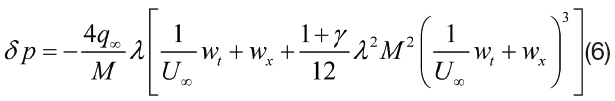
to account for the flap deflection is presented next. Within the PTA, the unsteady pressure can be defined as follows
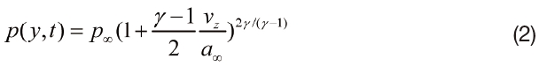
where

In the definition of

denotes the upper and lower surfaces, respectively, while
where
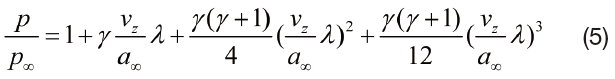
The aerodynamic correction factor,
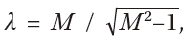
is used to correct the PTA to better approximate the pressure at low supersonic flight speed regime. It is important to note that (2) and (5) are only applicable as long as the transformation through contraction and expansion can be consider isentropic,
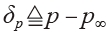
difference can be expressed as
Notice that
Finally, the nonlinear aerodynamic lifting and moment can be obtained from the integration of the difference of pressure on the upper and lower surfaces of the airfoil
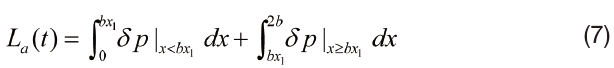
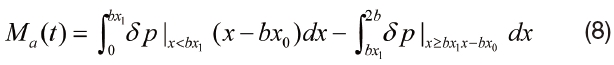
where δp+
Here,

where
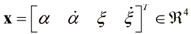
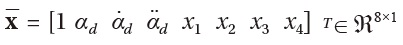
is a vector of systems states,
where the explicit definitions for the constants
III. Control Objective and Zero Dynamics
The explicit control objective of this paper is to design a model-free aeroelastic vibration suppression strategy to guarantee the asymptotic convergence of the pitch angle

plunging displacement ξ and plunging displacement velocity

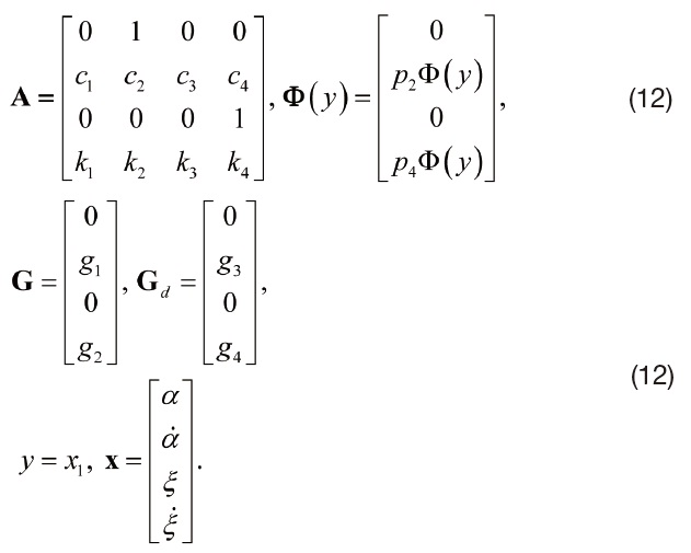
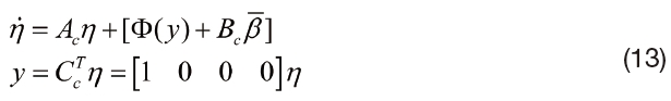
Since the proposed control strategy is predicated on the assumption that the system of (12) is minimum phase, the stability of the zero dynamics of the system needs to be assured. For that purpose, the system of (11) is transformed into the following state-space form
Where

=

is a new vector of system states, while
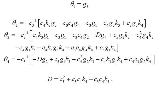
are explicitly defined as follows
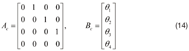
where
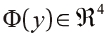
denotes a nonlinearity that encodes the nonlinear structural stiffness. It is to be noted here Φ(0) = 0. The state-space system of (13) can be expanded into the following from
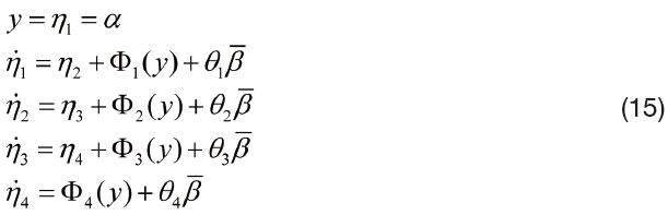
Here, the stability of the zero dynamics is studied for the case when the pitch displacement is
regulated to the origin. Mathematically, this implies that
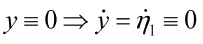
which implies from the second equation of (15) that
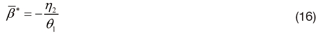
Since Φ1(0) = 0. The zero dynamics of the system then reduce to the reduce to the third order system given by
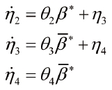
Substituting (16) into the above set of equations for

we obtain the linear system of equations
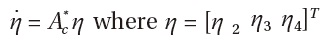
and A*c is given by
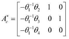
For the nominal system of (15), the eigenvalues of
IV. Open-Loop Error System Development
Given the definitions of (13) and (14),

can be expressed as follows

The tracking error
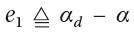
is defined where

denotes the desired output vector which needs to be smooth in deference to the requirements of the subsequent control design. For the control objective, one can simply choose

and the filtered tracking error signal

as follows


where
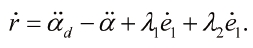
By substituting (17) for
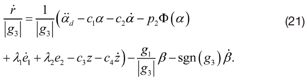
in the above expression, the open-loop dynamics for
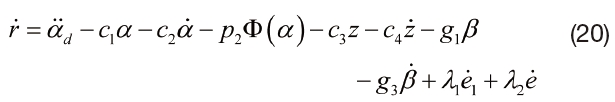
After a convenient rearrangement of terms, the open-loop dynamics can be rewritten as follows
In order to design a model-free controller, we define an auxiliary nonlinear signal
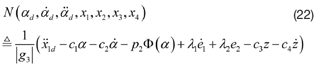
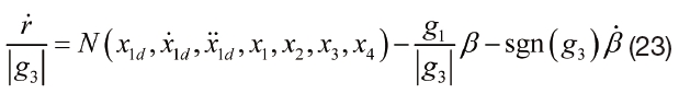
By utilizing the definition of (22) above, the open-loop dynamics of the system can be compactly
rewritten as follows
V. Control Design and Closed-Loop Error System
Since the structure of the model is assumed to be unknown in the control design, standard adaptive control cannot be applied. In its lieu, a neural network feedforward compensator

along with a robustifying term is proposed to compensate for the function

as long

to

and the set of inputs to the function is restricted to a compact set
. In (24),
denotes the augmented input vector, vector
is the ideal first layer interconnection weight matrix between input layer and hidden layer,
denotes the sigmoidal activation function, while
denotes the ideal second layer interconnection weight matrix. In this work, the weight matrixes W and V are assumed th be constant and bounded as ∥W∥F ≤ WB and ∥V∥F ≤VB, where WB and VB are positive constants. The approximation error is assumed to be bounded in compact set ∥ε∥ < ε
After substituting the approximation from (24) into (23), one can rewrite the open-loop dynamics as follows
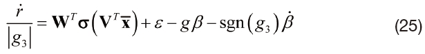
where

Motivated by the open-loop dynamics and the ensuing stability analysis, the control law is designed as follows

where

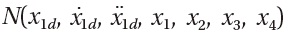
is typical three-level neural network compensator for target function

defined as follows


where the parameter projection operator
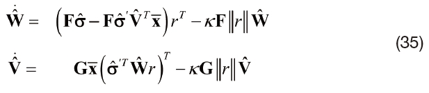
are estimates for the neural network interconnection weight matrices that are dynamically generated as follows
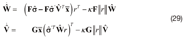
where

and

are postive definite diagonal gain matrixes, while
where

is a parameter estimation error. Also note that we can write

where the weight estimation errors are defined as
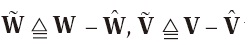
while

To facilitate the subsequent analysis, one can also obtalin a compact form representation for ∥w∥ follows
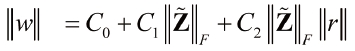
where

and the composite weight mismatch matrix
are given as follows
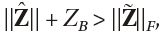
Per the boundedness property for ∥W∥ F and ∥ W∥ F as described above, there exists a constant
Where

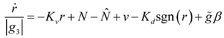
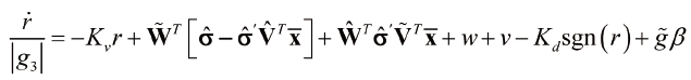
is assumed to be bounded. Thus, the closed-loop dynamics can be finally written as
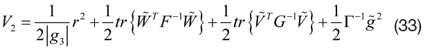
In this section, we provide the stability analysis for the proposed model-free controller. We begin by defining a nonnegative Lyapunov function candidate
After differentiating

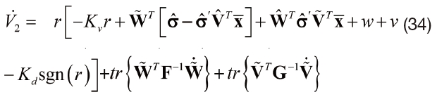
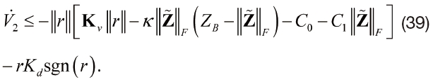
After applying the neural network weight update laws designed in (29), canceling out the matched terms and utilizing the definitions of (31), (35) can be upperbounded as

By substituting (30) and (32) into (36), it is possible to further upperbound
as
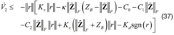
where the following relation has been used to derive
Based on the fact that
one can choose
By defining
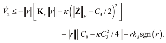
By choosing
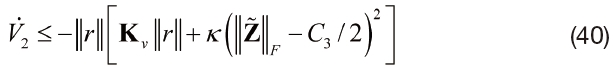
From (34) and (40), it is easy to see that
The boundedness of
are bounded by virtue of the definitions of (18) and (19). Since the system is minimum phase and relative degree one, the boundedness of the output guarantees that any first order stable filtering of the input will remain bounded. This implies that all system states remain bounded in closedloop operation which further implies that
stays bounded. Since (26) defines a stable filter acting on a bounded input, it is easy to see that

stay bounded; furthermore, the flap deflection control input

by virtue of the closed-loop dynamics of r. Thus, using previous assertions, one can utilize Barbalat's Lemma [33] to conclude that
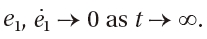
From the asymptotic stability of the zero dynamics, we can further guarantee that
In this section, simulation results are presented for an aeroelastic system controlled by the proposed continuous robust controller. The nonlinear aerodynamic model is simulated using the dynamics of (1), (7) and (10). The nominal model parameters are list as follows
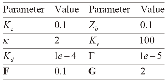
[Table 1] Controller Parmeters

Controller Parmeters
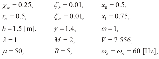
and the controller parameters are listed in Table 1.
The desired trajectory variables
are simply selected as zero. The inital conditions for pitching displacement
The effect of structural nonlinearities on LCO amplitude was analyzed before applying any control. As shown in [22], increase in structural stiffness factor denoted by B led to decrease in LCO amplitude provided the flutter speed
remains constant. Furthermore, we also explored the effect of the location of the elastic axis from the leading edge. It was shown in [22] that a decrease in
LCO amplitude while the flutter speed increases. It was also shown that increasing the damping ratios
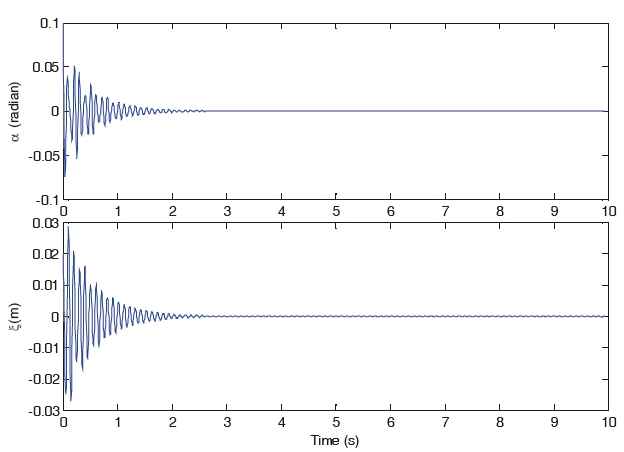
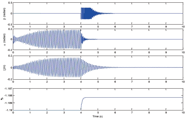
Fig 2 shows the dynamics of open-loop pitching displacement
Without the controller, it is obvious that the oscillation of pitching degree-of-freedom
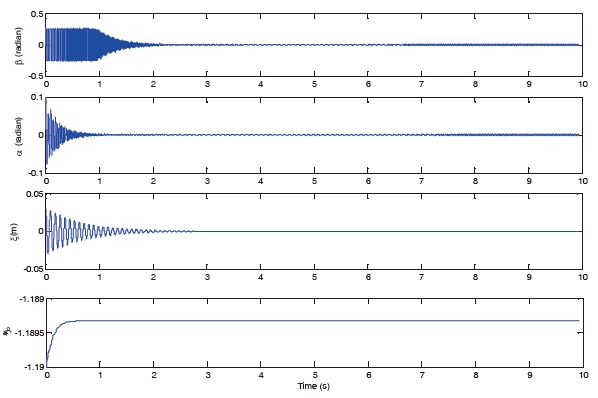
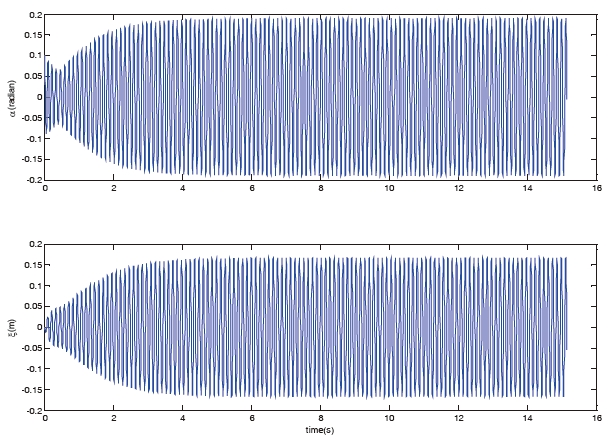
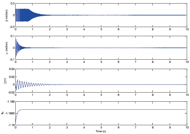
Another set of simulations is run for post-flutter speed. As shown in Fig 4, when M is set to be 3, the system dynamics show sustained limit cycle oscillations in open-loop operation. Such LCOs is experienced due to the non-linear pitch stiffness and the aerodynamic nonlinearities. After applying the control to the plant, from Fig 5, it is shown that when the control is turned on at t=0[s], the oscillation of
These simulation results show that the proposed novel robust controller can effectively suppress the oscillation of both pitching and plunging degrees-of-freedom of the airfoil in both pre-flutter and post-flutter flight speed regimes.
A modular model-free continuous robust controller was proposed to suppress the aeroelastic vibration characteristics (including flutter and limit cycle oscillations in pre- and post-flutter
condition) of a supersonic 2-DOF lifting surface with flap. Differently from traditional adaptive control strategies, which strictly require the linear parameterization of the system, no prior knowledge of the system model is required for the method presented in this paper. A Lyapunov method based analysis was provided to obtain the global asymptotic stability result. Finally, the simulation results showed that this control strategy can rapidly suppress any aeroelastic vibration
in pre- and post-flutter flight speed regimes.
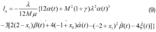
The auxiliary constants as well as and that were introduced in the model description of the state-space model are explicitly defined follows
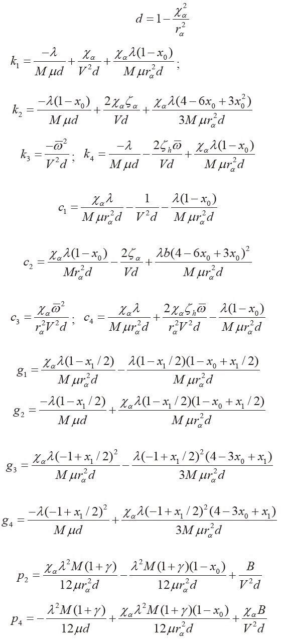
The elements introduced in (15) are explicitly defined as follows