During the last half century, much research investigating new airfoil design or modification of existing airfoils have been conducted. Especially, transonic small disturbance (TSD) theory may be applied in the aerodynamic design of wings of civil transport airplane and military fighters and in the design of helicopter blades, compressors, and turbines. Many algorithms for Euler solutions or Navier-Stokes equations for transonic flows demonstrate the difficulties in understanding the aerodynamic characteristics of the flows and its complex nonlinear nature as the geometry, the angle of attack, and the speed are changed [1]. However, theoretical approaches to transonic flow which can clarify its nature will provide a useful tool for aerodynamic analysis and the design of airfoils and wings in such conditions [2].
To improve the aerodynamic performance of civil airplane and fighter wings in transonic flows, Whitcomb et al. [3] suggest the supercritical airfoil which consists of a flat upper surface and cambered lower surface in the trailing edge. Such a flat upper surface creates a shock wave delay in which shock waves may appear beyond the critical Mach number. This delay results in the reduction of drag around airfoils. Also the cambered lower surface in a trailing edge compensates for lift loss around the wings due to a flat upper surface. Spaid et al. [4] modify the supercritical airfoil of Whitcomb a little and measure the surface pressure and drag around the modified airfoil over the range of the far field Mach number, 0.6 < M∞ < 0.8. It is then compared and analyzed with the aerodynamic performance of the NACA0012 airfoil. Harris [5] also develops the SC(1, 2)-0174 airfoils which is the modified supercritical airfoil. It is a 14% thick airfoil designed for a lift coefficient of 0.7. This airfoil is tested not only at transonic speeds but also at low speeds in the Langley wind tunnel. In particular, the effects of varying Mach number from 0.10 to 0.32 at a Reynolds number of 6.0 x 10⁶ are included in the wind-tunnel test results [5]. McGhee et al. [6] developed new NASA lowand mid- speed airfoils from the initial low-speed family airfoils. The thickness ratio of the initial airfoils designed for a sectional lift coefficient of 0.4 is changed from 9% to 21%. The new NASA airfoils are developed to increase the cruise Mach number of low-speed airfoils while retaining good high-lift and low speed characteristics. For example, the new NASA airfoils are designed for
Rusak et al. [7] investigate the improvement of the aerodynamic efficiency of small-scale airfoils by using a temperature differential between the upper and lower surface and the heat transfer effect with numerical simulations, asymptotic analysis, and experimental work. In the experimental work, the microrotor blades with 6-in (15.24-cm) diameters are spin tested at several blade pitch angle settings ranging from 9 to 15 deg. The microrotor blades are fabricated by using a commercial thermoelectric alloy material that exhibits the Peltier effect which occurs when any two members of the thermoelectric series are connected to form a junction. The application of a control voltage across the thickness of the airfoil results in a temperature differential between the upper and lower airfoil surfaces. This temperature differential influences the rotor aerodynamic performance, and this is measured and compared with the computational results.
As stated above, the supercritical airfoil to enhance the aerodynamic performance of civil airplane wings flying in a transonic regime is developed and its aerodynamic characteristics are tested for both transonic speed and low speed. The results are compared with aerodynamic characteristics of NACA0012 airfoil.
In the present study, the experimental investigations of the aerodynamic characteristics for modified sonic arc airfoils in low speed regimes are conducted as the continuing work of references [8,9] which are numerical studies for this airfoil in both transonic flow and low speed flow. This airfoil is designed by using the nose shape function of sonic arcs proposed by Rusak [10], the shape function of NACA fourdigit wing sections, and the commercial program Maple.
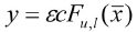
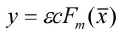
The special modified airfoil with a higher critical free stream Mach number and with lower pressure drag at transonic speeds can be constructed by using TSD theory. We call it a “modified sonic arc airfoil”. This airfoil is characterized by arcs which are close to the sonic arc along the forward part of the airfoil up to the maximum thickness point and which connect to a sharp tail. It has a nose shape given by equation (4) and a tail angle of NACA four-digit airfoil family (a sharp tail is used for practical aerodynamic reasons to minimize the boundary layer separation near the trail edge). This newly-designed airfoil is described by the formula

Here

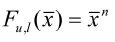
is the surface function of modified sonic arc airfoil. The surface function
can be obtained as follows.
Using the TSD theory, Schwendenman et al. [11] show that the asymptotic shape of sonic arc
is given by the parametric representation:
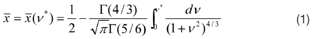
where -∞ <
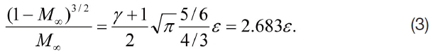
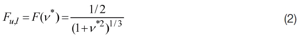
This is the highest critical Mach number which can be achieved for any airfoil with a given thickness ratio at zero angle of attack. Equation (1)-(3) describe a sonic arc at a zero angle of attack. The flow around the sonic arc was studied in detail by Rusak [10]. He suggests that the arc shape at the nose of the asymptotic shape (as
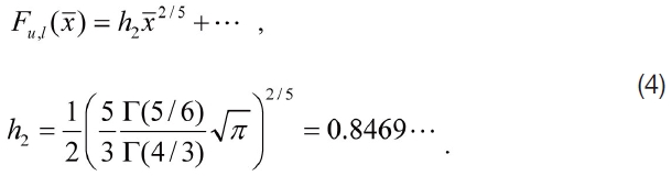
The

nose shape is exactly the nose of the sonic slender semi-infinite body. This special nose shape results in minimal pressure drag contribution among all the power law shapes
with 2/5≤
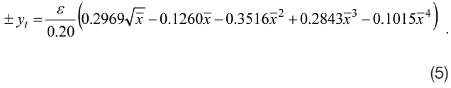
The thickness distribution for NACA four-digit wing sections [12] is given by the formula;
Now, we can construct the modified sonic arc airfoil with a nose shape of the body given by equation (4) and a tail angle of NACA four-digit wing sections. Experience with computations shows that the maximum thickness of this airfoil should be located at

=0.415 for the highest critical free stream Mach number. The modified airfoil shape
is given by the formula;

where
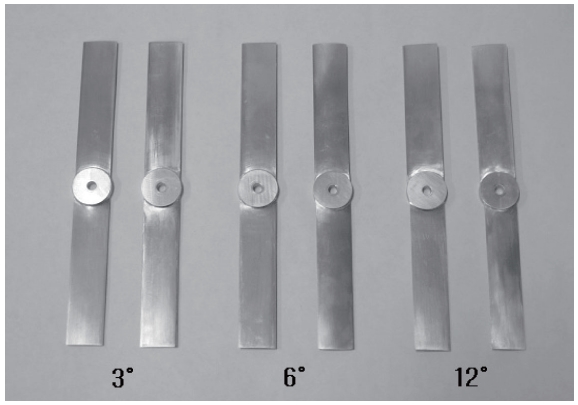
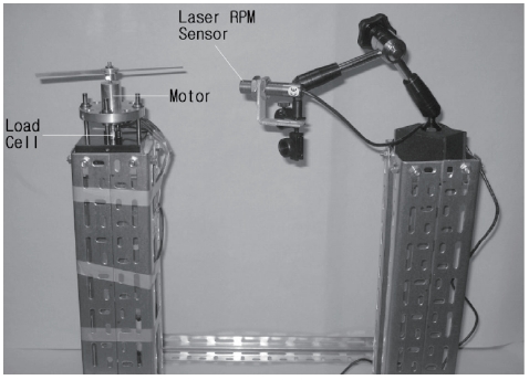
To investigate the aerodynamic performance of the modified sonic arc airfoil, the small rotor blades of the modified sonic arc and NACA0012 airfoil are spin tested like in reference [7]. First, the rotor blades of the modified sonic arc and NACA0012 airfoil are designed with CATIA which is a commercial drawing program, and then the rotor blades are accurately fabricated with a commercially available light aluminum(Al 6061-T6) using the 5-axis high speed manufacturing machine called CAM (computeraided manufacturing) machine. Fig. 2 shows the rotor blades with pitch angles where the diameter of the rotor blade is 18cm and the diameter of the hub is 2.2cm. The experimental apparatus consists of a highly sensitive load cell for measuring rotor thrust, a laser light source coupled to a frequency counter to measure rotor speed, and a corelessdc motor with associated fixtures which connect the rotor blades to the motor output spindle. Fig. 3 shows the test apparatuses mounted on two columns (50cm height and
50cm distance). The rotor blades are tested from 3000rpm to 5000rpm in room temperature (293.15K) in a low-humidity environment. The platform is rectangular (no taper or sweep), the aspect ratio is 4.5 [9cm radius and 2cm chord], camber is 0%, and the blades are untwisted. The test data for the hovering rotor is collected by the commercial program LabView. The rotor blades are tested at several blade pitch settings ranging from 3 to 12 degree. In order to obtain accurate data, the load cell is fitted on the zero adjustment first. Motor speed is increased by a control lever and we keep the rotor rotating up to the steady state at a fixed rpm. Then ten data per second are collected for ninety seconds by Labview. The mean value of the collected data is calculated and this mean value is regarded as the thrust at a given rpm.
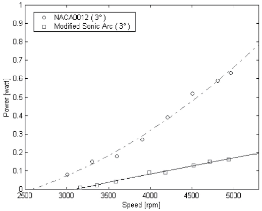
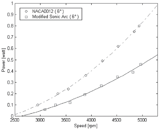
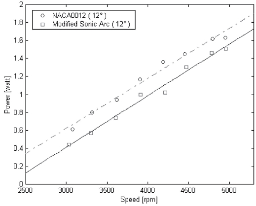
The measured consuming powers for NACA0012 and modified sonic arc airfoils at a given pitch angle are shown in Fig.4 ~ Fig.6. The curve fitting lines analogized by the least-square regression method are added in all the figures. The consuming powers are increasing as rotor blade speeds are increased in all the figures. Moreover, the consuming powers of NACA0012 are higher than that of the modified sonic arc at each pitch angle. As the pitch angle is increased, the consuming power for both two airfoils is also increased. For example, at a 3 deg. pitch angle, the estimated values of consuming power are 0.52[watt] for NACA0012 and
0.13[watt] for the modified sonic arc at about 4500[rpm]. At a 6 deg. pitch angle, it is 0.62[watt] for NACA0012 and 0.35[watt] for the modified sonic arc at about 4500[rpm]. At a 12 deg. pitch angle, it is 1.45[watt] for NACA0012 and 1.30[watt] for the modified sonic arc at about 4500[rpm].
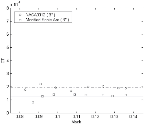
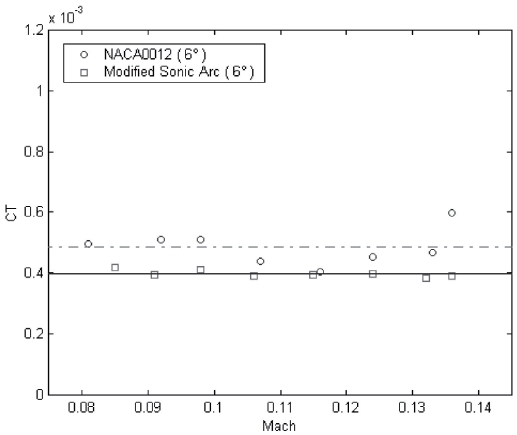
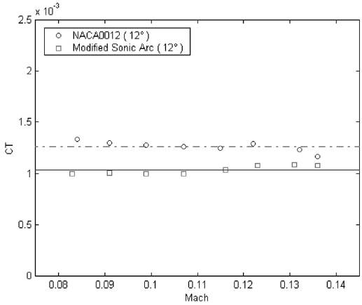
The experimental data of thrust for each pitch angle are listed in Table 1~Table 3. These measured rotor thrusts for each pitch angle are used to estimate the rotor thrust coefficients according to momentum theory in the hover state [13]. The rotor thrust coefficient is defined on the basis of the rotor disk area A and the tip speed
[Table 1.] Thrust[gf] Measurement for a 3 deg. pitch angle
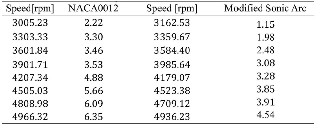
Thrust[gf] Measurement for a 3 deg. pitch angle
[Table 2.] Thrust[gf] Measurement for a 6 deg. pitch angle
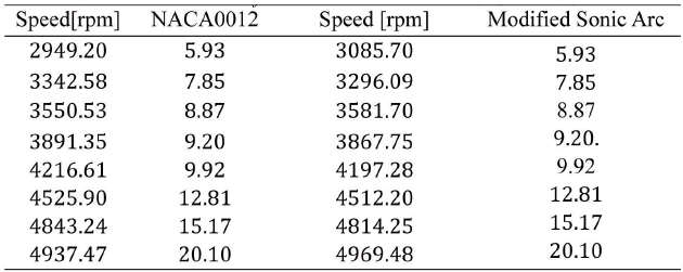
Thrust[gf] Measurement for a 6 deg. pitch angle
[Table 3.] Thrust[gf] Measurement for a 12 deg. pitch angle
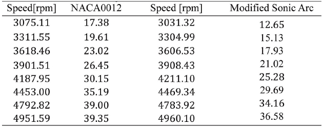
Thrust[gf] Measurement for a 12 deg. pitch angle
rotor thrust coefficient of the modified sonic arc at a given pitch angle. When the pitch angle is doubled, the rotor thrust coefficient of NACA0012 is increased by two and a half times and that of the modified sonic arc is increased by two and a half or three times. Therefore, the aerodynamic performance of NACA0012 is better than that of the modified sonic arc in the low speed regime (3000rpm-5000rpm).
The low speed aerodynamic characteristics of the modified sonic arc airfoil which is designed by using the nose shape function of the sonic arc, the shape function of NACA four-digit wing sections, and the Maple are experimentally investigated. The small rotor blades of the modified sonic arc and NACA0012 airfoil are precisely fabricated with a commercially available light aluminum(Al 6061-T6) using a 5-axis high speed manufacturing machine and then they are spin tested over the low speed range (3000rpm-5000rpm). In the consuming power comparison, the consuming powers of NACA0012 is higher than that of the modified sonic arc at the given pitch angle. The measured rotor thrust is used to estimate the rotor thrust coefficient. The value of the rotor thrust coefficient at each pitch angle shows to be almost consistently over the low Mach number range. For example, the average thrust coefficient for NACA0012 is 0.000198 and that for the modified sonic arc is 0.000128 at a 3 deg. pitch angle. In conclusion, the aerodynamic performance of NACA0012 is better than that of the modified sonic arc in the low speed regime. This test model will provide a convenient platform for improving the aerodynamic performance of small scale airfoils and for performing design optimization studies.


![Thrust[gf] Measurement for a 3 deg. pitch angle](http://oak.go.kr/repository/journal/11292/HGJHC0_2012_v13n3_317_t001.jpg)
![Thrust[gf] Measurement for a 6 deg. pitch angle](http://oak.go.kr/repository/journal/11292/HGJHC0_2012_v13n3_317_t002.jpg)
![Thrust[gf] Measurement for a 12 deg. pitch angle](http://oak.go.kr/repository/journal/11292/HGJHC0_2012_v13n3_317_t003.jpg)