BR blockage ratio (=dF,o2/dA2)
dF,i inner diameter of fuel tube
dF,o outer diameter of fuel tube, diameter of bluff body
Lf flame length
Um,A air mass-weighted velocity (=ρAUA/ρA,ref=?A/(ρA,refAA))
Um,F : fuel mass-weighted velocity (=ρFUF/ρF,ref=?F/(ρF,refAF))
τ : air to fuel mass flux ratio (=ρAUA/ρFUF)
ρAUA : air mass flux
ρFUF : fuel mass flux
τR,A : global residence time of air (dF,i/Um,A)
τR,F : global residence time of fuel (dF,i/Um,F)
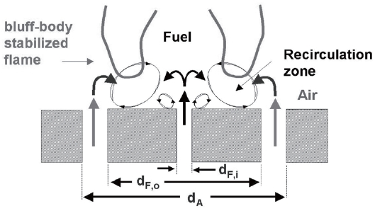
Bluff-body nozzles are basic devices for stabilizing both premixed flames and non-premixed flames. The coflow air entrains a part of the central fuel jet into the low-speed recirculation zone in the wake of the bluff body, and then combustion mixing stabilizes the flame. With a bluff body, the flame characteristic changes from a pure diffusion flame, classically stabilized on the burner surface, to a partially premixed flame stabilized in the recirculation zone [1].
The structure of bluff-body stabilized flames has been investigated by numerous researchers. The relation between flame structure and flame stability was identified. Kundu et al. [2] investigated flame stabilization by bluff-bodies to highlight the role of the recirculation zone. They observed that close correlations exist between heat exchange from the recirculation zone and flame stability, which were controlled by the strength of recirculation. Roquemore et al. [3] studied the dynamic behavior of bluff-body diffusion flames by using spectrophotometers. They found largescale turbulence downstream of the recirculation zone, and showed a quasi-periodic decrease in frequency of the turbulence with the distance from the exit. Masri and Bilger [4] classified three flame types based on the penetration of the central jet through the recirculation bubble: short flame, transitional flame, and central fuel jet-dominated flame. However, most flames were classified according to the fuel/ air velocity or momentum ratio. Huang and Lin [5] identified seven characteristic flame modes: recirculated, transition, unsteady detached, laminar ring, developing, split flashing and lifted flame modes. Chen et al. [6] defined a detailed regime diagram for flame lift-off and stabilization limits, and classified the bluff-body stabilized flames: recirculation zone, jet-dominated, and jet-like flames. They showed that lift-off stability is more sensitive to the coflow air velocity than to the fuel jet velocity.
In recent studies, laser diagnostics were used to obtain more details on flame structures. Chin and Tankin [7] used a laser sheet lightening technique for low-Reynolds-number flows in a two-dimensional vertical bluff body burner. They defined three regimes according to the fuel penetration into the recirculation zone: pre-penetration, penetrationtransition and penetration regimes. Masri et al. [8] measured the mixture fractions, temperatures, and OH radicals of the flames to reveal the structure of the recirculation zone in a bluff-body stabilized flame by using a joint Raman-Rayleigh- LIF image technique. They found that double reaction structures appear more frequently, and these structures shift to the center of the main vortex as the fuel-to-air velocity ratio increases. Using PLIF imaging, Yang et al. [9] found that the position of the reaction zone moves upstream from the outer shear layer of the air driven vortex as the velocity ratio increases. Yang et al. [10] also showed that the recirculation zone bubble provides a low-velocity environment and prolongs the stagnation of the reactant. The stagnation prolongation is a key factor for stabilizing the flame as the fuel-air velocity ratio becomes large.
Bluff-body nozzles play an important role in stabilizing flames in supersonic coflow air [11]. However, few studies have focused on supersonic flames, especially bluff-body stabilized flames featuring elevated flow velocities up to supersonic conditions. Cheng et al. [12] measured the temperatures and the concentrations of several species in a supersonic combustor by using UV Raman scattering and LIPF (Laser-Induced Predissociative Fluorescence). They reported that more intense turbulent fluctuations are observed in supersonic flames than in subsonic flames, and that strong reaction occurs in the upper part of the flames. Driscoll et al. [13] identified the various factors that affect the flame length in a confined combustor. They showed that the lengths of supersonic flames are shorter than those of subsonic flames at the same velocity ratio or at the same density ratio, and that the flame lengths decrease as
The detailed flame structures and the modes of bluffbody stabilized flames in supersonic ranges are not clearly understood. We investigated the structures of unconfined hydrogen diffusion flames in a supersonic coflow of air (
2. Experiments and Analysis Methods
2.1 Supersonic Combustor and Conditions
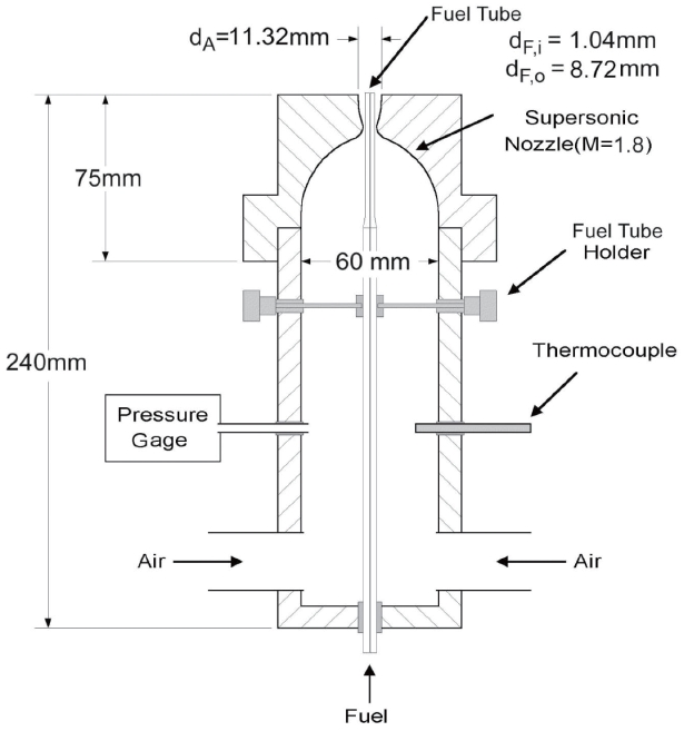
Figure 1 shows a small-scale supersonic combustor. The supersonic air nozzle was designed by the characteristic method and manufactured, so that the expansion ratio of the supersonic air nozzle (
number of the supersonic combustor was 1.8. The fuel tube had an inner diameter (
Fuel tubes with a thick lip were used to stabilize supersonic flames, because a thick tube lip acts as a bluff body and defines the size of the recirculation zone, as shown in Fig. 2. With a fixed inner tube diameter (
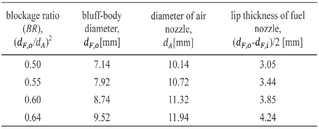
Dimensions of fuel tubes and air nozzles at each blockage ratio. Inner diameter of fuel tube and exit areas of coflow air are fixed (dF,i=1.04mm, π(dA2-dF,o2)/4=40.8 mm2).
To investigate the effects of coflow velocity on the structure of hydrogen flame, we varied the air velocity from subsonic to supersonic conditions. The mass flow rate or the momentum flux can be used as a parameter when defining the flame types and analyzing the flame stability, but velocity is generally adopted in the analysis of characteristic modes of bluff-body stabilized flames in the subsonic range [5,6,
The mass-weighted velocity is directly proportional to the measured mass flow rate of the mass flux, as shown in Eqns. (1) and (2). The mass-weighted velocities of air and fuel (


These are defined as the value of the mass flux divided by the gas density at standard conditions:
The values of the mass-weighted velocity in the subsonic range of
The axisymmetric Navier-Stokes equation for multiple species was employed to analyze the mixing of hydrogen fuel with coflow air. The conservation form of the governing equations including balance equations for N species may be written as follows:

In this expression, Q is a conservative variable; F and G are convective fluxes; Fv and Gv represent diffusion fluxes; and H and Hv correspond to source terms associated with cylindrical coordinates. The details of the governing equations and thermal properties are described elsewhere
In the simulation, the grid resolution was 160× 150. A noslip boundary condition was used at the bluff body. The grid independence was tested with finer grid sizes. The selected grid size was fine enough to resolve the qualitative trends without the loss of detailed information obtained with the use of finer grid sizes. In this non-reacting condition, the mixing of fuel jet and coflow air was studied numerically.
OH PLIF was used to obtain spatially and temporally resolved images of the reaction zone within the supersonic combustor. The OH radical concentration increased rapidly around the flame in about 20 μsec and then decomposed slowly in 1 to 5 ms by a 3-body recombination reaction
For OH PLIF, an Nd:YAG-pumped dye laser was turned to the Q1(6) transition of the
3.1 Stability Curve of Bluff-body Stabilized Flames
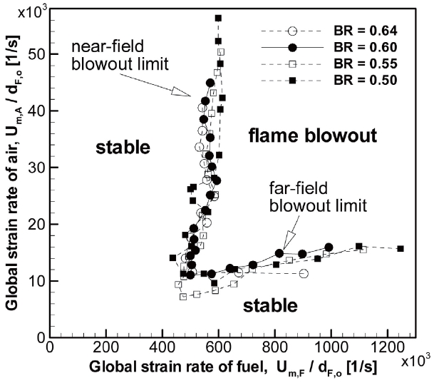
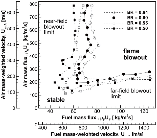
Figure 3 shows the flame stability curves of a bluff-body stabilized flame. There are two distinct lobes in the stability curve of this flame, and each lobe is affected by different physical parameters, such as the lip thickness of the fuel tube, coflow air temperature, and fuel or air velocities
In many studies, the air and fuel velocities are generally used as the variables of flame stability curves. The flame stability curves indicate the conditions and ranges for the existence of the flame, because the stable equilibrium position of the flame and the stability limit can be explained in terms of flame propagation velocity with respect to the gas velocity [4,5,
Figure 3 shows the stability curves of the bluff-body stabilized flame at each blockage ratio from 0.50 to 0.64. The larger blockage ratio corresponds to the thicker lip of fuel tube, as shown in Table 1. The inner diameter of the
fuel tube was fixed to maintain the same fuel jet condition in each case, but the outer diameter of the air nozzle was changed to increase the blockage ratio and to conserve the exit air flow area. Figure 3 indicates that stability was improved by increasing the lip thickness (or blockage ratio) of the fuel tube in the near-field blowout limit. The fuel tube with larger lip thickness acted as a bluff-body and provided a larger recirculation zone. This enlarged recirculation zone broadened the low speed region, and this broadening stabilized the flame. However, the far-field stability limit was not affected by the variation of the fuel tube lip thickness, because the central-jet dominated flames were slightly affected by the change of bluff-body size.
Figure 4 shows the stability limits of the global strain rates, which are the mass-weighted velocities normalized by bluff-body sizes, respectively (outer diameter of fuel nozzle,
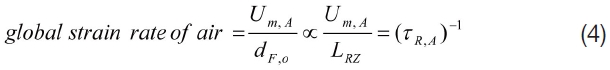
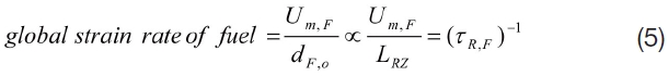
where
to extend this relation to the supersonic range. If the global residence time is defined as the time required for flow to cross the recirculation zones, the flame can be stabilized when the global residence time is large. From Fig. 4, the stability of the bluff-body flame is related to the global strain rate (or the global residence time), and the larger the fuel tube thickness, the greater the increase in the flame stability, because of a larger recirculation zone and the prolonged mixing of fuel and air.
3.2 Combustion Diagram for Bluff-body Stabilized Flames
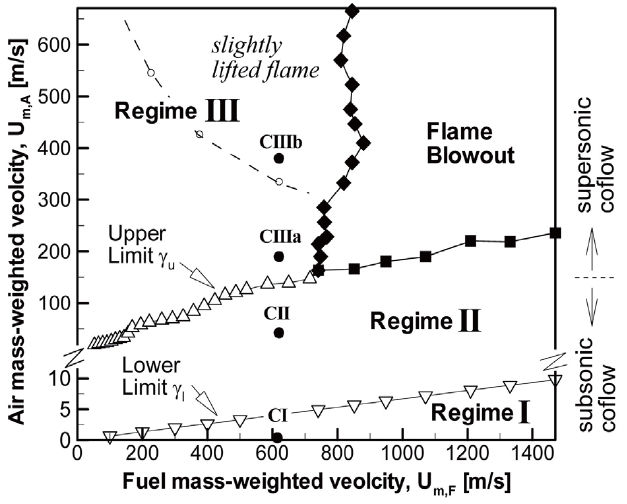
Figure 5 shows a combustion diagram with different regimes for a bluff-body stabilized non-premixed flame. The blockage ratio of this flame is 0.60. γ=
Generally, hydrogen/air flames have a large laminar burning velocity, because such mixtures have a short induction time and large heat release values. Thus, hydrogen flames can be maintained for a wider range of velocities up to supersonic conditions than hydrocarbon fueled flames [4,6]. In the present study, the flame stabilization at higher flow velocity was attributed to the high blockage ratio and energetic hydrogen fuel. When the fuel jet has much higher momentum (Regime I), the central fuel jet penetrates
through the recirculation bubble. When the fuel jet and annular air momentums are similar to each other (Regime II), a central-jet dominated flame can develop. This flame mode is characterized as a narrow-waist flame. When the fuel jet momentum is too weak to penetrate the recirculation bubble (Regime III), all fuel mass or most of the fuel mass will be retained behind the bluff body to form a recirculation zone flame. More specifically, Regime III was divided into two modes: open-tip flame and closed-tip flame.
3.3 Effect of Coflow on Supersonic Flames
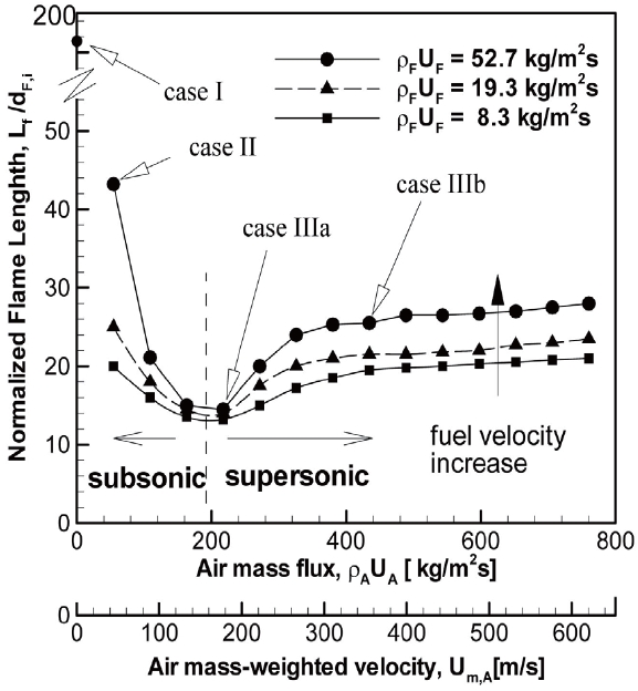
The visible length of the supersonic flame is the measure of the fuel-air mixing rate, which affects the flame stability process. Rapid mixing produces a short flame. A long flame has stoichiometric contours further downstream, with reduced strain rates. Figure 6 shows the variation of flame length according to the increase in the air mass flux. The flame length normalized by the inner diameter of fuel tube (
In the subsonic coflow ranges, the flame length decreases with increasing air mass flux. This decrease was due to the increased mixing by a small quantity of the high-velocity fuel penetrating the center of the recirculation region. However, in the supersonic ranges, the flame length increases slowly and then eventually reaches a near-constant value. This phenomenon was attributed to the air-entrainment of subsonic flow and the compressibility effect of supersonic flow, which will be explained by the results of the mixing simulations.
Experimental conditions of coflow air at the exit plane of the supersonic combustor having a bluff-body (BR= 0.60, dF,i= 1.04 mm, dF,o=8.72 mm, dA=11.32 mm) with a fixed hydrogen fuel condition (ρFUF=52.7 kg/m2s, Um,F=620 m/s, Re=6000, To,F= 294 K ).
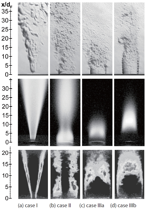
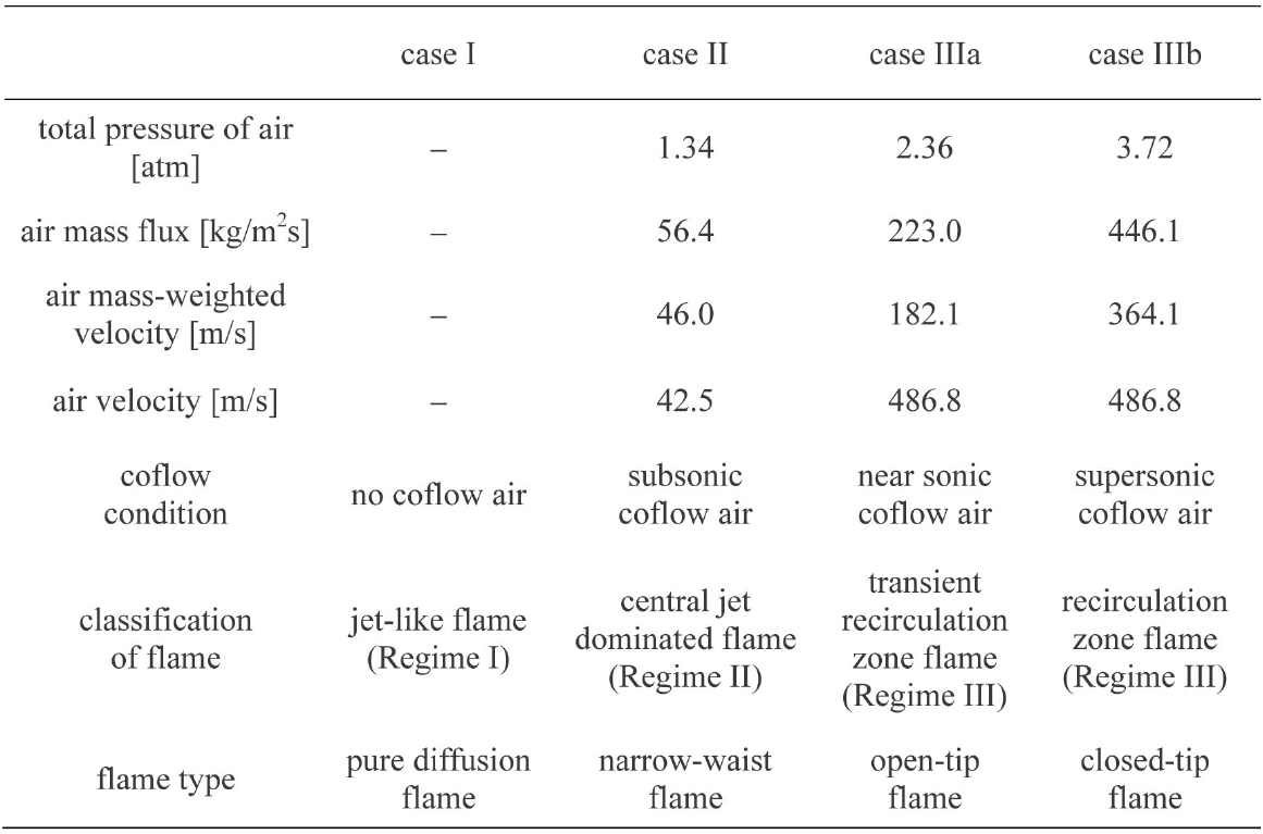
To investigate the flame structures with the change of air velocity, we fixed the hydrogen fuel mass flux at 52.7 kg/ m2s, and the Reynolds number of fuel was about 6,000. The detailed operating conditions are given in Table 2 and are indicated in Fig. 7 for cases I, II, IIIa and IIIb, respectively. These conditions represent the typical characteristics of each type of flame. Different visualization methods were used to analyze the structure of these flames.
Case I is the pure diffusion flame, which has no coflow air, as shown in Fig. 7a. Its OH PLIF image indicates that the reaction zone was established along the shear layer between the fuel jet and ambient air. As the air mass flux was increased slowly from zero to the value near the condition of case II, the flame shape was changed to the narrow-waist shape, as shown in Fig. 7b. At the narrow waist of the flame, a high strain rate zone was created by the strong entrainment of high-momentum coflow air. The highly strained zone decreased the reaction rates and local extinction thus occurred. The OH radical image marks a concentrated region along the boundaries between the fuel and air, and indicates a local extinction in the narrow waist of the flame (at
When the air-fuel mass flux ratio γ exceeded 0.2, the jetdominated flame of Regime II was changed to a recirculation zone flame of Regime III, as shown in Fig. 7c. When the air
mass flux was increased to that of case IIIa and the subsonic flames were changed to supersonic flames, the flame started to shrink and finally became extinct in the upper part of the narrow waist. This phenomenon is attributed to the large amount of air entrained towards the flame. In the condition of case IIIa, the flame had the shortest length and an open-tip shape, as shown in the OH PLIF images. In this case, the stagnation point was formed just downstream of the recirculation zone, but the jet penetrated the recirculation zone intermittently. Thus, case IIIa was classified as a transient recirculation zone flame, because the characteristics of the central jet-dominated flame remained.
As the airflow velocity is further increased, as shown in case IIIb for the supersonic flame, the flame became longer and thinner with a closed-tip shape, as shown in Fig. 7d. The high intensity region of the OH radicals moved from the vicinity of the recirculation zone to the center of the flame, because the centerline stagnation point may have acted as an effective source of fuel. The anchoring point of this supersonic flame was at the outer edge of the outside recirculation zone near the exit of the bluff-body fuel tube, as suggested by others
The supersonic flame is slightly lifted in case IIIb. A flame lifts off when there is an imbalance between flame propagation and an opposing fuel flow [11]. In this study, the flame lifted at a higher air velocity (
3.4 Simulation of Fuel-Air Mixing
Non-reacting simulations were not sufficient for the prediction of reacting flow phenomena, because the interaction between combustion and aerodynamics was not considered. Despite this limitation, we used non-reacting simulation results as supplementary data for understanding the flow characteristics near the fuel tube exit.
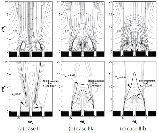
Figure 8 shows the simulation result of the mixing of hydrogen jet and coflow air, which did not chemically react. The top figures in Fig. 8 show pressure contours (dashed lines) and streamlines (solid lines). The bottom figures show hydrogen mass fraction contours (thin solid lines) and the stoichiometric line (thick dashed line) of
To predict the possible flame location with the OH radical region, we defined the expected-flame region as the area between the 1% hydrogen mass fraction contour (
In case II of Fig. 8a, the coflow air jet with relatively small momentum moved toward the centerline along the outer stream of the recirculation zone, and then the coflow air abruptly changed its direction when it met the fuel jet. This directional change may cause a large strain rate at this point, inducing a flame waist. Consequently, this high strain rate almost extinguished the flame locally and thereby reduced the reaction rate.
The pressure field in case II was relatively uniform throughout the flame zone, whereas those of cases IIIa and IIIb varied. The low pressure zone (0.72~0.93 atm) existed near the fuel nozzle exhaust (cf. Fig. 8b), whereas the relatively high pressure zone (1.34~1.13 atm) was located on the downstream side of the recirculation zone. The fuel jet expanded abruptly as it passed through the lowpressure zone and then lost its momentum by the blockage of the high-pressure zone. Thus, the fuel jet may follow the border of the recirculation zone without crossing the highpressure zone. Hence, the fuel jet had more time to mix with the air entrained along the recirculation zone. Due to the increased mixing time, the partially premixed zone was formed downstream of the center stagnation point. This is believed to explain the formation of partially premixed flame characteristics observed in cases IIIa and IIIb. An increase in the coflow air momentum tended to augment the size of the recirculation zone, where the flame can be stabilized in the supersonic airflow, as illustrated in Fig. 8.
As shown in Figs. 8b and 8c, the extent occupied by the stoichiometric line in case IIIb is reduced more that in case IIIa, but the vertical position of the 1% line (
These expected-flame regions explain the abrupt decrease in the subsonic flame length and the slow increase in the supersonic flame length. In the subsonic coflow range, coflow air was entrained to the fuel jet and the mixing of fuel and air was enhanced, and thus, the flame length was reduced with increasing air mass flux. However, once the air coflow reached the supersonic coflow air condition, mixing became independent of the amount of entrained air, but it was mainly controlled by increased compressibility effects. Thus, the partially premixed zone was located further downstream from the fuel nozzle, and finally, the flame was elongated due to the limited mixing.
3.5 Structure of Supersonic Flames
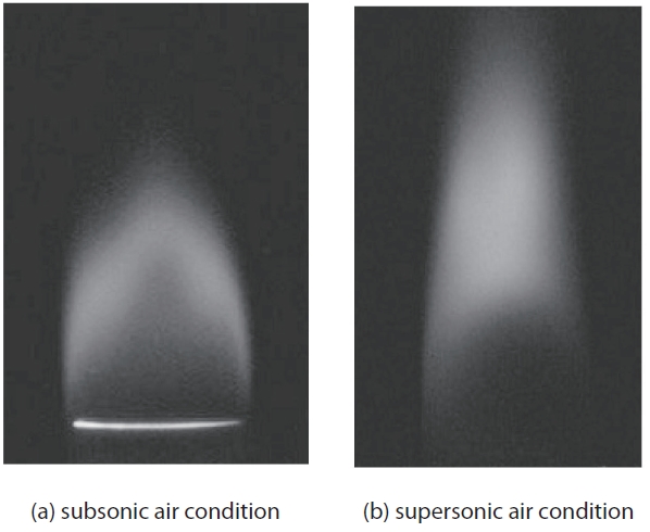
The recirculation zone flame can exist in both subsonic and supersonic coflow conditions. However, the flames corresponding to these two conditions are different. Figure 9 shows the subsonic and supersonic flames at the same air-to-fuel mass flux ratio (γ=0.6), which corresponds to the recirculation zone flame condition. Although both flames were similar, the locations of highly reactive layers corresponding to subsonic and supersonic flow conditions were different. In the subsonic case, the chemical reaction mainly occurred around the outer shear layer of the downstream recirculation zone, whereas in the supersonic
case, the reaction core was moved downstream of the center stagnation point. Recent LDV and OH PLIF measurements [9,10] on flames stabilized on bluff-bodies in subsonic flow conditions showed that the main reaction zone exists at the outer shear layer of the air-driven vortex.
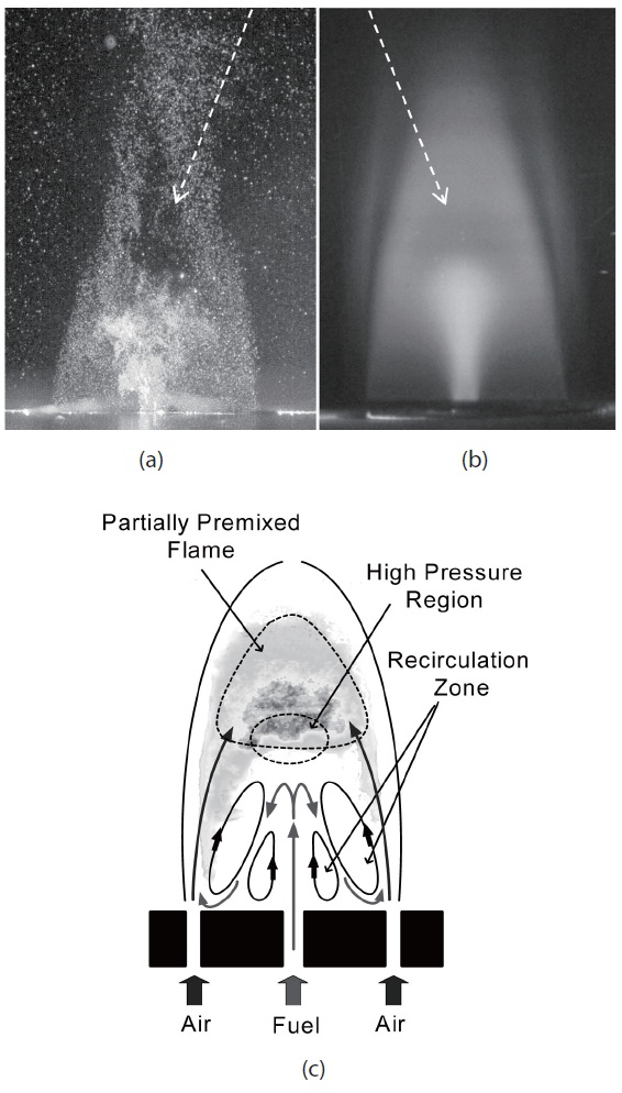
To find the fuel jet trajectory experimentally, we obtained scattering images for non-reacting flow by illuminating the flow with a planar laser sheet. Particles (TiO2) are seeded in the fuel flow. Figure 10a is an instantaneous image taken with an Nd:YAG laser, and Fig. 10b is a long-exposure image taken with an Ar-ion laser. These two images indicate that a low scattering zone existed on the downstream side of the fuel jet. The trajectory of fuel observed in these pictures was
similar to that obtained from the simulation shown in Fig. 8c. Using the direct photographs, Schlieren photographs, OH PLIF images and numerical simulation, we can construct a schematic representation of the supersonic flame structure, as shown in Fig. 10c.
The most noticeable characteristic of supersonic flames is the partially premixed zone on the downstream side of the stagnation point. Partially premixed flames are expected to form behind the bluff-body [1]. The fuel jet is blocked by the high-pressure zone and loses its momentum, and thus circulates through the recirculation zone. Finally, a partially premixed zone can exist at the flame center, because relatively longer fuel-air mixing time is available in supersonic flames. A reacting core is also found at the flame center, and a short flame length is obtained by the longer mixing time within the partially premixed zone. This mixing and the reaction processes are illustrated in Fig. 10c in the flame with supersonic coflow air. A reacting core is found at the flame center, and features characteristics of a partially premixed flame. This reacting core suggests that the flame structures may differ from that of a subsonic flame.
We investigated the structure of bluff-body stabilized hydrogen flame with high-speed coflow air varying from subsonic to supersonic velocities of up to Mach 1.8. Stability curves were plotted to find the blowout regimes. The flame blowout stability was improved by the use of a thicker fuel tube, which works like a bluff-body. When the global strain rate was defined as mass-weighted velocity normalized by the bluff-body size, each stability curve collapsed to a single line. This collapse means that the flame stability was related to the global residence time (inverse of the global strain rate) of the flow in the stabilized flame. The flame stabilization modes were classified into three regimes: (i) jet-like flame, (ii) jet dominated flame, and (iii) recirculation zone flame. The upper and lower limits of air-fuel mass flux ratios (γ
The flame length changed independently of the fuel mass flux. The minimum flame length was observed at the same air mass flux condition of 200 kg/m2s, which was similar to the transition condition from subsonic to supersonic speed. The subsonic flame length decreased with increasing air mass flux, whereas the supersonic flame length increased with air mass flux and finally reached certain value limits. When the coflow was in the subsonic ranges, air was entrained into the fuel jet and the mixing of fuel and air increased. Hence, the flame length reduced with increasing air mass flux. However, once the air coflow reached supersonic conditions, mixing did not depend on the entrained air, but was controlled by the increased compressibility effect.
The structures of the flames were illustrated by various means, including direct photographs, Schlieren photographs, Mie scattering and OH PLIF images. OH PLIF images of the recirculation zone flame with supersonic coflow showed that the reaction zone existed on the downstream side of the recirculation zone. However, in the central-jet dominated flame having subsonic coflow, the reaction zone existed on the inner side of the recirculation zone. The recirculation zone flames of Regime III could also be divided into two modes: open-tip flame and closed-tip flame. The opentip flame became a closed-tip flame when the coflow air increased, which is believed to be related to the increased compressibility effects.
Fuel mass fraction contours were deduced from each case of the non-reacting flow simulation. The expected-flame region was defined as the area between the stoichiometric line and the 1 % mass fraction of hydrogen obtained from numerical simulation. This region coincided well with the regions of OH radicals obtained by PLIF imaging. From the expected-flame region of the supersonic coflow condition (case IIIb), the location of the partially premixed zone was predicted, and a reacting core was expected in the supersonic flame.
In the closed-tip recirculation zone flame (supersonic flame), the fuel jet lost its momentum because of the high-pressure zone, and the fuel jet developed along the recirculation zone. The fuel had more time to mix. This increased mixing time may have produced the partially premixed flames rather than non-premixed flames. The blockage of the fuel jet and the formation of the partially premixed zone were confirmed by laser light scattering images and simulation results.