Communication, Ocean and Meteorological Satellite (COMS, Chollian) was launched on July 26, 2010 and is now in operation successfully (Lee et al. 2011). COMS Satellite Ground Control System (SGCS) is developed by Electronics and Telecommunications Research Institute (ETRI), and the algorithm of parameters and events for COMS satellite configuration is developed according to the document provided from Astrium to ETRI (Laine 2006).
In the launch and early operation period (LEOP) or in the situation where the attitude of a satellite is not nor-mal, the satellite attitude is not known and thus it should be fixed to a specific direction in order to acquire the nor-mal attitude. The position of the sun is used as the ref-erences to fix the satellite attitude in a specific direction.The sun acquisition refers to the process to fix the satel-lite attitude with reference to the solar position. Once the sun acquisition is completed, the position of the earth is kept in the vision of the satellite by adjusting the three-axis attitude of the satellite with reference to the relative position of the sun and the satellite. When the initial at-titude of the satellite is stabilized, the normal attitude is kept by obtaining the field of view (FOV) toward the earth by means of the earth observation sensor.
This paper describes mainly the earth acquisition pro-cess after the sun acquisition in case that the status of COMS changes from on-station to abnormal. Based on the orbit information for the COMS earth acquisition, the article describes the method to search the proper time periods considering the constraints for calculating the appropriate time when the earth acquisition can be per-formed following the sun acquisition. In case of perform-ing the earth acquisition for COMS at the selected one of the calculated time period, the algorithm and simulation result for attitude maneuver process, maneuver time and duration is verified. The actually realized earth acquisi-tion parameter results of COMS are compared with the results of the Astrium control software.
2. COMS EARTH ACQUISITION COORDINATES
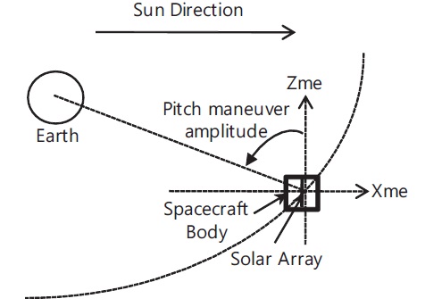
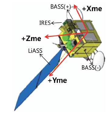
This chapter describes the coordinate frame required to perform the earth acquisition. Fig. 1 shows the defini-tion of the spacecraft mechanical frame of COMS as well as the sensor position accordingly. The +Zme direction passes through the imaging equipment from the center of mass of the satellite and it is equal to the viewing di-rection of infra-red earth sensor (IRES). The +Xme is per-pendicular to the +Zme direction and equal the satellite translational direction. The +Xme is equal to the viewing direction of bi-axis sun sensor (BASS) which is one of the sun sensors. The sun sensor which is on the position of azimuth +90 degree with reference to the +Zme axis on the Xme-Zme plane is ACQ+ BASS and the one on the position of azimuth -90 degree is ACQ- BASS. The +Yme direction is defined by the right hand law and it passes through the plane on which the solar array is established from the center of mass of the satellite. Linear accurate sun sensor (LiASS) is on the plane where the solar array panel cell is established.
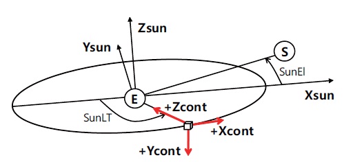
Fig. 2 shows the reference frame and the spacecraft control frame used in this article. The reference frame refers to the sun elevation (SunEl) at a certain time and the solar angular local time (SunLT) of the satellite. Zsun is perpendicular to the orbital plane to the north. Xsun is the axis of the vector in the sun direction projected on the orbital plane. Ysun is determined by the right hand law. The +Zcont axis of the spacecraft control frame is directed to the center of the earth from the satellite. The +Xcont axis is perpendicular to the +Zcont axis and in the direction of the satellite velocity. The +Ycont is defined by the right hand law (Laine 2006).
The earth-sun direction and the earth-spacecraft di-rection vectors on the reference inertial (RI) frame can be expressed as in the following equation where RI uses to the reference frame for COMS earth acquisition:


3. EARTH ACQUISITION ALGORITHM
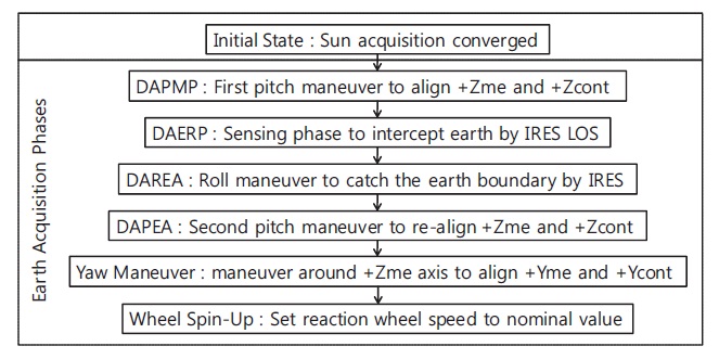
The on-station earth acquisition of COMS refers to the attitude control of the satellite that makes the +Zme Axis be in the direction to the center of the earth after com-pleting the sun acquisition. At the time when the sun acquisition has been completed using BASS and LiASS, the coarse pointing has been performed with the Xme or ?Xme axis to the sun direction through BASS, and the precise pointing is performed by means of LiASS (Laine 2006). After the sun acquisition, the earth acquisition is implemented through the process described in Fig. 3 (Paddack 1964).
The satellite pitch maneuver is performed with refer-ence to the angle of rotation of LiASS pointing to the sun (Fig. 4). After performing the pitch maneuver, the +Zme axis points the earth. At this time, the range and period of the pitch maneuver are determined by the position of BASS for the sun acquisition and the target attitude angle. This procedure is called deployed array pitch maneuver phase (DAPMP). If the DAPMP is finished, the earth is located in the FOV of the IRES in the +Zme axis direc-tion. The next procedure is deployed array earth research phase (DAERP) where the earth's boundary is scanned. The types of IRES trance used for the scanning and the searching rate of the IRES sensor are determined by the command parameter defined on the ground. The +Zme axis determined by DAERP points to the earth. Then, to adjust the Xme axis and the Yme axis, deployed array earth acquisition in roll (DAREA) and deployed array earth acquisition in pitch (DAPEA) are implemented. Finally, the satellite comes to have the normal attitude oriented to the earth by performing the Yaw Maneuver that aligns the +Yme axis with the +Ycont axis which is perpendicular to the orbit. Then, the complete process of the earth acquisition is finished by performing the wheel spin-up procedure where the reaction wheel speed is ad-justed to the nominal value.
4. CONSTRAINT PERIOD CALCULATION ALGO-RITHM
This chapter describes the algorithm to calculate the available time slot that is needed to determine the initial time of the earth acquisition implementation. To perform the earth acquisition normally, there should be no inter-fering elements such as sensor intrusion and eclipse in the commanding period of earth acquisition and consid-er the pre-computed maneuver time. When all condition
for the earth acquisition is satisfied as calculating the time which the satellite events are occurred, the earth acquisi-tion time is determined. At this time, the initial state of the earth acquisition is after the sun acquisition and thus the satellite and the solar array are oriented to the sun. If the solar position cannot be found from the position of the satellite because of eclipse by the earth or the moon, the sun acquisition is impossible. Thus, the sun acquisi-tion cannot be implemented normally until the eclipse exit. The attitude control duration and the actuation are determined with reference to the position of the sun also in the DAPMP procedure, DAPM cannot be implemented during eclipses. Even when it is not during eclipses, the earth acquisition commanding and monitoring are not possible if the communication with the ground station is not established, the position of the earth should be inside the telemetry/telecommand coverage during the DAPMP procedure. The DAERP and DAREA procedures are also impossible during eclipses, as in the previous proce-dures. Additionally, the earth searching through a sensor is impossible if there is intrusion by the sun or the moon inside the FOV of IRES. Hence, the DAERP and DAREA procedures need to be implemented avoiding the period of IRES blinding by the sun or the moon. The earth acqui-sition process is postponed if there is intrusion by the sun or the moon with respect to both of the traces that can be used for the earth searching in IRES. Since the Yaw atti-tude is controlled by the LiASS and IRES measurement in the DAPEA procedure, the period which is free of eclipses and IRES blinding should be secured. During the Yaw maneuver procedure, the angle of elevation by the LiASS bending should be less than 90 degree. The wheel spin up procedure does not affect the constraint for calculating the available time-slot.
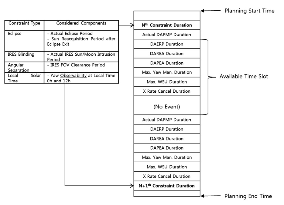
The initial time for the earth acquisition should be se-lected as one of the time slots, excluding the constraint periods where there is an interfering element to the atti-tude maneuver. Thus, to derive the available time slot, the constraint period where there is an interfering element to the attitude maneuver needs to be calculated. The con-straint periods are the eclipse period, IRES blinding pe-riod, minimum angular separation period and the local solar time (LST) separation period.
The minimum angular separation constraint is ob-tained by calculating the satellite position on the orbit at which the IRES FOV may not be intruded by the sun while implementing the attitude maneuver as well as the mar-gin range of the IRES FOV. The LST constraint is obtained by calculating the range on the orbit to perform efficient Yaw maneuver estimation except the periods when the local time is noon or midnight. The attitude maneuver is not implemented during the eclipse periods, and the buf-fer period for the sun reacquisition following an eclipse should be considered. Fig. 5 shows the range of time slots where the earth acquisition operation can be normally implemented in the whole planning period. The earth ac-quisition phase is implemented repeated for each avail-able time slot.
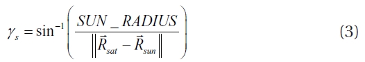
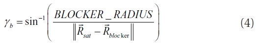
The eclipse that may occur to COMS, a geostationary satellite, is the one where the sun is eclipsed by the earth or by the moon. If the position of the satellite on the orbit is known, the eclipse, which is one of the elements that constitute the constraint periods, is calculated as follows (Soop 1994):
where

denotes the position of the satellite on the orbit,

the position of the sun,

the position of the earth or the moon, SUN_RADIUS the radius of the sun and BLOCKER_RADIUS the radius of the earth or
the moon. The time when the eclipse occurs is when
Since the normal earth acquisition by IRES may be interfered by the sunlight when the LST is noon or mid-night, the period around those times need to be deter-mined as the constraint periods. The times at which the LST is noon or midnight can be calculated using the satel-lite position as follows:
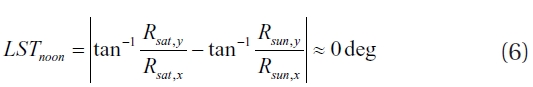
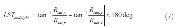
where
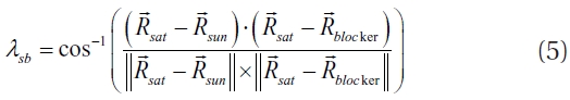
Considering the effective range of the IRES FOV, the separation angle (α) between the satellite and the sun and between the satellite and the earth should satisfy the fol-lowing range (Laine, 2006):

or

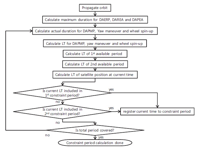
Totally two constraint periods can occur by the LST constraint and the angular separation constraint with reference to the local time of which entire range is 360 degree. To calculate the constraint period for the plan-ning period, the duration of each of the earth acquisition phases should be taken into account in a constant time interval over the entire period planned for the earth ac-quisition. Fig. 6 shows the process to calculate the LST constraint period and the angular separation constraint period.
Fig. 7 shows the example for IRES blinding by the earth or moon. If the pathway of the sun or the moon is No. 1 during the earth acquisition, there is no constraint in the IRES trance used for the earth acquisition. However, if the pathway of the sun or the moon is No. 2 or No. 4, a trace without intrusion should be used. If the pathway of the sun or the moon is No. 3 where intrusion occurs in both the north trace and south trace, the earth acquisition is impossible. Occurrence of IRES intrusion at a specific time can be determined as follows:
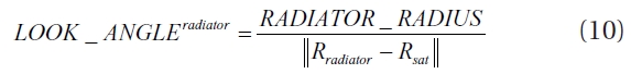
If the looking angle of the radiator such as the sun or the moon has been calculated,


If the conditions are satisfied, the IRES sensor intru-sion occurs. In these inequalities,

the position of the sensor axis X (or Y) in the body frame,

the position of the sun or the moon in the body frame and

the width (or height) angle of the IRES FOV.
After calculating the period of the individual elements causing the constraints, the individual constraint periods are merged to derive the available time slots where the earth acquisition can be actually implemented. The nom-inal earth pointing is acquired by setting a certain time among the available time slots as the initial time or the DAPMP start time and implementing the sun reference rotation in the actual duration of the attitude maneuver for each phase of the earth acquisition.
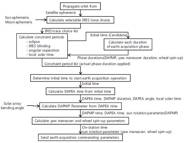
The COMS sun acquisition prior to the earth acquisi-tion is implemented according to the automation se-quence of the sun sensors which are BASS and LiASS. After completing the sun acquisition, the earth acquisi-tion is implemented using the solar array drive mecha-nism and IRES, the earth searching sensor. If a series of earth acquisition procedures are completed, the Yaw axis is oriented to the earth within the error range of 2 degree and the reaction wheel is recovered to the normal speed. The earth acquisition developed by ETRI is implemented progressively following the steps shown in Fig. 8. The in-put information for the earth acquisition algorithm im-plementation includes the epoch orbit element and the initial time of the DAPMP operation commanding. The final results which should be sent to COMS are the IRES trace parameter used in the DAERP procedure and the sun rotation parameters that should be oriented at the
individual procedures such as DAPMP, DAPEA, yaw ma-neuver and wheel spin-up phase.
To prepare the fundamental data needed to implement the earth acquisition algorithm, orbit propagation is per-formed from the time when the station acquisition is
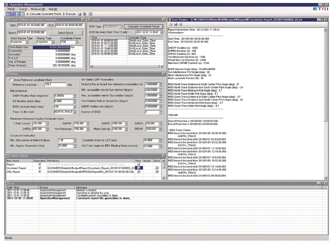
completed to the time when the earth acquisition should be completely performed. If the orbit data are generated during the period, the local midnight time and the sun elevation angle of the satellite can be calculated, and the IRES trace choice list available for the period can be gen-erated. In the whole period, the initial time is selected excluding the periods when the normal earth acquisi-tion is not guaranteed such as eclipses, the IRES blinding period, the angular separation angle constraint and LST constraint periods in order to calculate the earth acquisi-tion commanding parameters. Fig. 9 shows the graphic user interface of the software developed to implement the earth acquisition operation described in this article.
Three orbital elements are considered to verifying the realized algorithm for the earth acquisition constraint periods, because the possible period of eclipse or IRES blinding should be selected to depend entirely on the sun and moon position. The epoch and orbital elements at the Table 1 are used, and these coordinate system is the true of date.
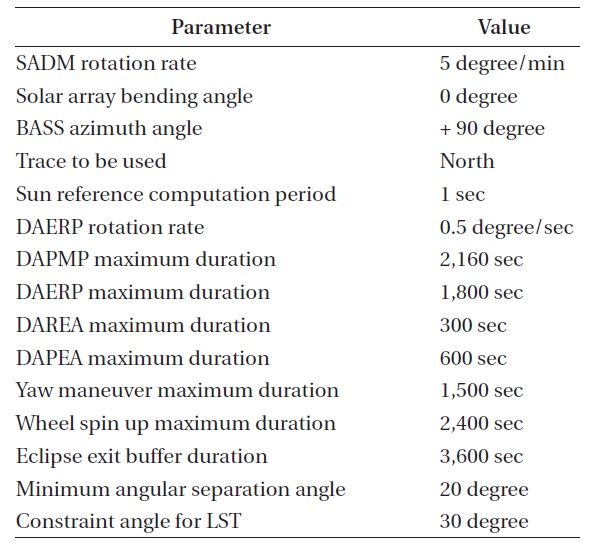
Table 2 shows the input parameters acquired from the default values of telemetry or the earth acquisition algo-rithm. These parameters are provided by the simulator of Astrium. Table 3 shows the calculated constraint periods
[Table 1.] COMS orbital elements.
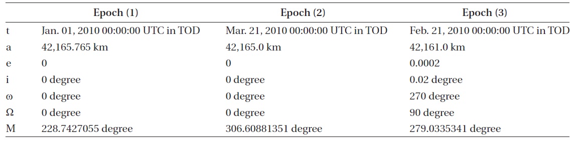
COMS orbital elements.
[Table 2.] Non-calculated (input) parameters for earth acquisition.

Non-calculated (input) parameters for earth acquisition.
[Table 3.] Constraint period calculation result validation.
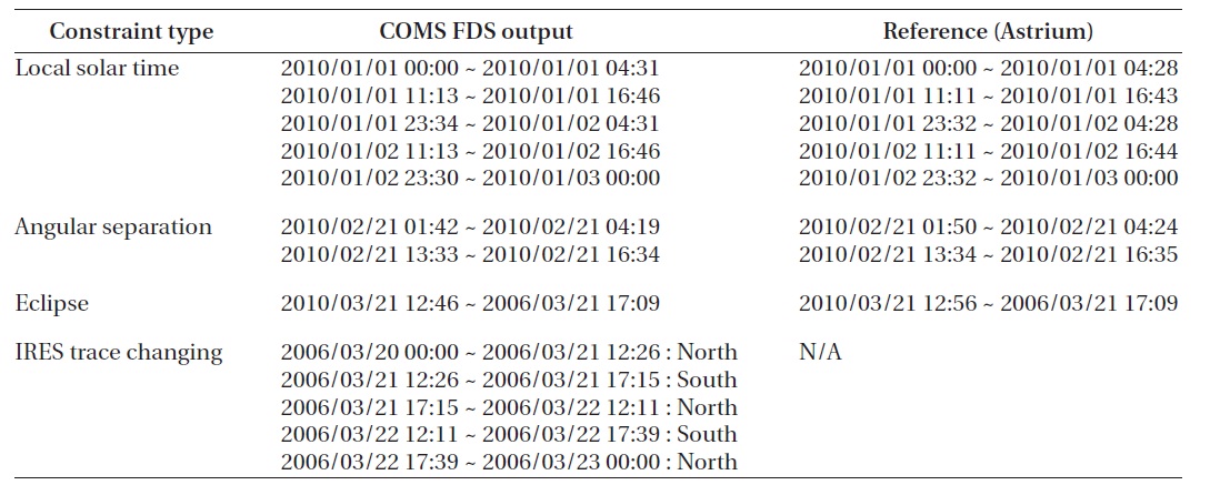
Constraint period calculation result validation.
and the IRES trace changing events by each of three time ranges. The flight dynamics system results realized in the COMS SGCS are compared with the reference results pro-vided by the Astrium technical papers (Laine 2006). The comparison showed that all the results are within the tolerance which is 10 minutes. The tolerance should be defined as the range of normal satellite operation when COMS performs the earth acquisition.
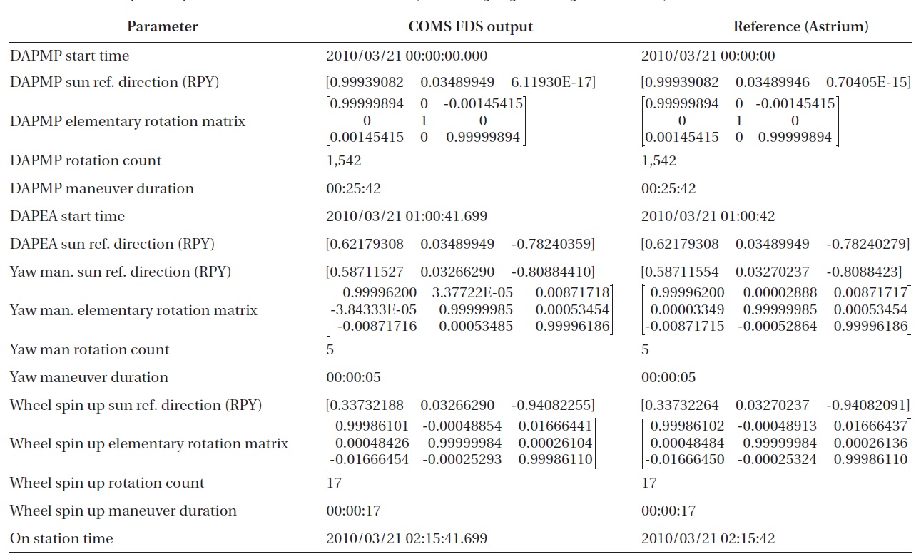
The calculated earth acquisition parameters are shown in Table. 4-6. These parameters are the sun direction vec-tor which is oriented for each phase, rotation matrix for the attitude which changes with each phase of the earth acquisition, and the maneuver duration of each phase. The comparison with the reference results also shows that the parameters are precisely within the tolerance.
This article described the earth acquisition of the COMS flight dynamic system and the verification of the
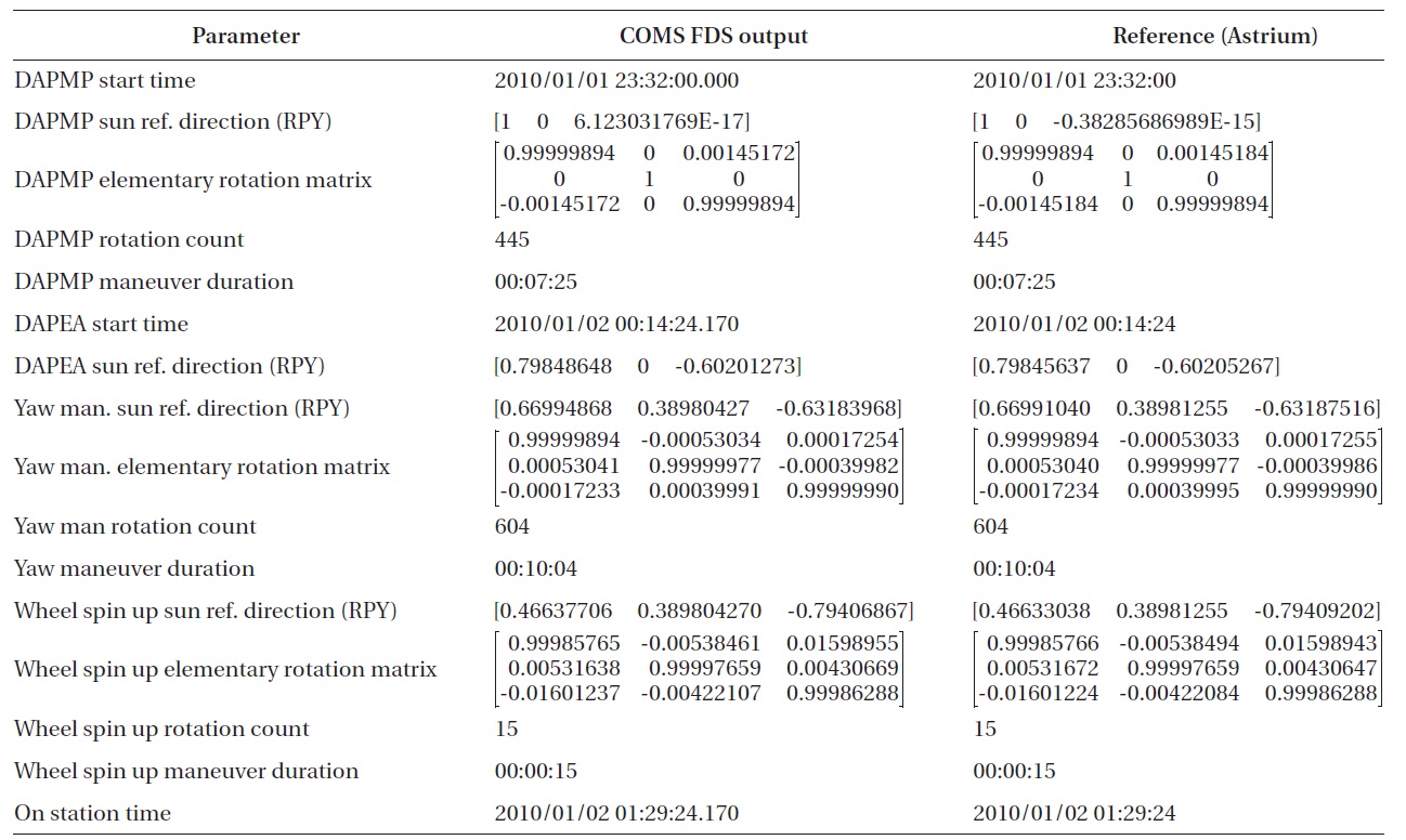
Earth acquisition parameter at January 1 2010 23:32:00 (SA bending angle = 0 deg +X BASS used).
results. Since the earth acquisition should be performed in LEOP or in the situation where the satellite attitude is not normal, verification of the module in the actual On-Station operation is not easy. This article technically described the mechanism about how the satellite in an abnormal attitude is re-oriented to the earth and the se-ries of procedures to calculate the time slots for the earth acquisition. The calculated results are compared with the result by the software realized by Astrium and verified to be within the tolerance needed for the operation. This showed that the developed earth acquisition module can be applied to the actual operation without any problem.

Earth acquisition parameter at March 21 2010 00:00:00 (SA bending angle = 2 deg -X BASS used).
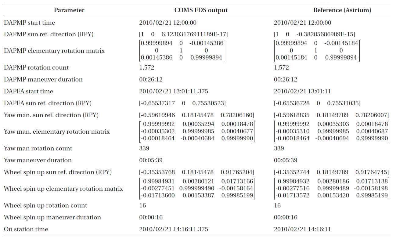
Earth Acquisition parameter at February 21 2010 12:00:00 (SA bending angle = 0 deg +X BASS used).