In a previous paper (Eleiche, 2010), it was concluded that in order to support innovative energy research projects funded by the CCWCE (2008), innovators should be provided with a software program that can help manage the effects of possible changes in design requirements (DR) and hence facilitate the design of successful quality systems on schedule and within planned budgets. It was also stated that guidance would be sought from similar research being carried out in the software engineering arena.
In the present paper, we address in detail the subject of DR, which is central to the design of software and engineering systems. The main reason for this is that quality aspects are usually closely tied to requirements, among other things. In this review paper, we consider how the subject of requirements is being managed in these two seemingly different disciplines. Two important aspects are covered, namely: (a) requirements development, describing various activities leading to re-quirements documentation, and (b) requirements change management, describing various activities needed for the proper treatment of the inevitable changes in requi-rements. Similarities and differences on how these two aspects are handled in software and engineering systems are highlighted. Important gaps and future important research areas are also identified.
The next section introduces the topics related to DR. in a generic way. This is followed in Section 3 by an overview of how DR development is treated in software and engineering systems, while Section 4 presents how DR management is being applied in these same two disciplines. Important conclusions are given finally in Section 5.
IEEE (1990) defines “Requirement” as a condition or capability that: (a) is needed by a user to solve a problem or achieve an objective, (b) must be met or possessed by a system or system component to satisfy a contract, standard, specification, or other formally imposed document. The set of all requirements forms the basis for subsequent development of the system or system component.
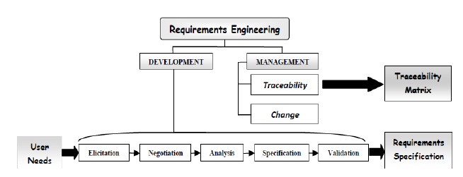
Requirements Engineering (RE) is a crucial aspect for a successful development of software and engineering systems. The RE process is the primary work of the “Requirements” phase of the project. Figure 1 shows the sub disciplines of RE (Wiegers, 2000) consisting of two major types of activities. In
3. REQUIREMENTS DEVELOPMENT (RD)
Requirements can be classified into: (a) Functional requirements that capture the intended behavior in terms of services, tasks or functions the system is required to perform; (b) Non-functional requirements (or system qualities) that capture required properties or qualities of the system; (c) Constraints (organizational, operational, economical, legislative, and ethical). All requirements must be carefully derived through analysis of user needs and documented. They should specify
A good requirement should be (Tavassoli, 2009): clear; complete; correct; consistent; verifiable; traceable; feasible; modular; adaptable; and design-independent.
Nowhere more than in the requirements process do the interests of all the stakeholders in a software or engineering system project intersect. These include: (a) external stakeholders (end users, customers acquiring the product, suppliers, distributors, subcontractors, legislators, policy makers); and (b) internal stakeholders (requirements analysts, project managers, developers, designers, manufacturing staff, testers, regulators and auditors, sales and marketing, purchasing and finance, and field support or help desk staff). Handled well, this intersection can lead to exciting products, delighted customers, and fulfilled developers. Handled poorly, it is the source of misunderstanding, frustration, and friction that undermine the product’s quality and business value.
Many software problems arise from shortcomings in the ways that people acquire, document, agree on, and modify the product’s requirements. Typical problem areas include informal information gathering, implied functionality, inadequately defined requirements, and a casual change process (SERENA, 2011). The widely quoted CHAOS report (Standish Group, 1995) relates the consequences of casual approaches to requirements engineering. Year after year, lack of user input, incomplete requirements, and changing requirements are the major reasons why so many software and information technology projects fail to deliver all of their planned functionality on schedule and within budget.
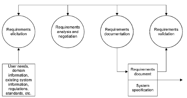
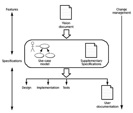
In software engineering, RE has already been accepted as an independent discipline and is done systematically. As will be seen in the following, many concepts and methods for handling of requirements have already been elaborated. Hence, a common terminology of process phases in RD has emerged, involving elicitation, negotiation, analysis, specification and validation. This is depicted in Fig. 2, as proposed by Kotonya and Sommerville (1998).
During the
During
During
Requirements
The many sections in the SRS document should detail various aspects of the software system to be developed, mainly: functional requirements, non-functional requirements, design constraints and interface specifications (Kotonya and Sommerville, 1998; Sommerville, 2007). IEEE (1998) has defined a standard known as “IEEE Std 830-1998” which provides guidelines for documenting software requirements specification.
The requirements document along with the models can be and should be managed using requirements management tools such as Telelogic DOORS or IBM Rational RequisitePro.
The requirements
By engineering systems, we mean consumer or capital products and systems ranging from simple to quite complex ones. Especially in modern energy applications, these may also incorporate many kinds of software, thus forming “hybrid systems” that contain material and immaterial parts. The following discussion will be limited to systems consisting of hardware only.
In engineering systems design, RD is usually taken into account, as stated in most engineering design textbooks. For instance, Cross (1989) suggests the use of a goal tree to vaguely collect the initial requirements. The requirements are further refined as the problem understanding of the customer and engineers increases. Pahl and Bietz (1996) suggest a sequential process model in which the engineer has to extract the requirements from the customer’s wishes. They also recognize that customers are often not able to express their requirements appropriately; however, methods for eliciting these requirements are not suggested. Ulrich and Eppinger (2008) collect the requirements in hierarchical weighted lists. They also state that it is important to reveal implicit customer needs, and that a common product understanding between customer and engineer is necessary.
In their comprehensive review, Jiao and Chen (2006) state that RD usually encompasses only the three activities of
Psychology-based approaches: where techniques such as Kansei engineering; Kawakita Jiro method, affinity diagrams, and laddering can be employed.
Methods and tools from the field of knowledge acquisition: where techniques employed can be:
(a) “Contrived” (not-heavily dependent on natural language dialogue, but good at reducing systematic bias, eliciting implicit knowledge, representing declarative and procedural knowledge): e.g. sorting, laddering, repertory grids.
(b) “Non-contrived” (traditional) techniques: e.g. surveys, observations, ethnography, self-reports, interviews.
AI-based approaches: where fuzzy systems, regression analysis, and expert systems have been developed for eliciting customer requirements more accurately and objectively. Also, integrated approaches by combining picture sorts and laddering, fuzzy evaluation and neural network techniques.
Knowledge recovery: from historical data.
Case studies of elicitation in practice are available in the literature. This is described by Mathelin
Activities in the Analysis phase consist of:
Understanding market and customer needs.
Customer preference.
Prioritization: By assigning different importance weights for customer requirements. This affects the target values to be set for the engineering characteristics. Existing techniques are:
(a) AHP (Analytic hierarchy process)
(b) Fuzzy AHP
(c) Using supervised learning with a radial basis function (RBF) neural network
(d) Applying conjoint analysis to prioritize customer requirements through pairwise comparisons
Classification: This helps guiding the designer in compiling, organizing, and analyzing product design issues. Existing techniques are:
(a) Affinity diagrams
(b) Ontology for representing requirements that supports a generic requirement process. Ontology defines parts, features, requirements and constraints
(c) Taxonomic approach (developing a set of taxonomies to assist in gathering, storing, using and reusing requirements)
Requirement transformation: e.g. Customer optimization route and evaluation (CORE) model; methodology of organizing specifications in engineering (MOOSE)
QFD. To translate customer requirements to technical design requirements
Fuzzy QFD: To enhance handling of ambiguous requirement information and evaluating inputs. Subjective crisp variables are expressed as fuzzy numbers
Prioritization of design requirements. Importance rating among engineering characteristics in the QFD; a linear programming model for the prioritization of design requirements in the QFD planning process; employing a fuzzy outranking approach to prioritize the design requirements in the QFD
Targets of design requirements: (usually defined by design teams subjectively and empirically) Using a fuzzy set theoretic approach to determine optimum target values for the engineering characteristics in QFD with consideration of the relevant constraints; using fuzzy regression and fuzzy optimization.
Therefore, as the RD phases proceed, the informally expressed needs of stakeholders are explored, developed and expanded into a more complete and formal document, variously known as the product description, technical specification, or
RD in software engineering is highly elaborated and many methods and process models are known. Software engineering sees RD as a continuous activity that is performed throughout the entire development process, while product/ systems engineering considers RD as a phase at the beginning of the project.
The specification of requirements in software engineering results from not only the transformation of customer requirements from those end-users, but also considerations of many engineering concerns. This is consistent with the principle of viewpoint-oriented software requirement engineering, where multiple viewpoints encapsulate different types of requirement models natural to different stakeholders.
4. REQUIREMENTS MANAGEMENT (RM)
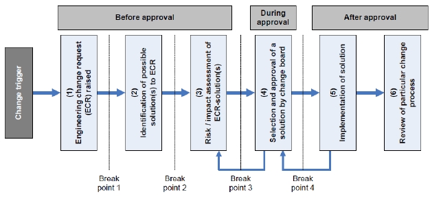
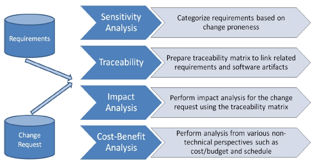
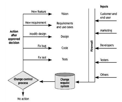
RM involves two main tasks, namely: (a) requirements traceability, performed once the specifications have been documented, in order to determine the links between various requirements; and (b) change impact analysis, conducted at any stage of the design process, once a change of any kind has been proposed, in order to determine the feasibility, implications, cost, etc, of such a change, and finally deciding on its approval, as illustrated in Figure 3.
Changes in requirements are always expected. Indeed, they are the norm and not the exception, since most complex projects involve interdisciplinary system scenarios. In these cases, the stakeholders needs are usually not fully identified, and hence the requirements and the specifications are loosely-defined. Therefore, those initial requirements can be expected to change for a variety of reasons, e.g. altered market needs, safety concerns, problem corrections, new constraints, introduction of new technologies, uncertainty of resources, cost considerations, legislation changes, etc. On the other hand, in such systems, components are usually highly interconnected; a change to one requirement in one component can propagate through the system and cause other changes in other components and parts. The change can also spread to other products (e.g. other family members) due to common platforms, other processes (e.g. manufacturing), and other businesses (e.g. suppliers, partners, etc.) (Jarratt
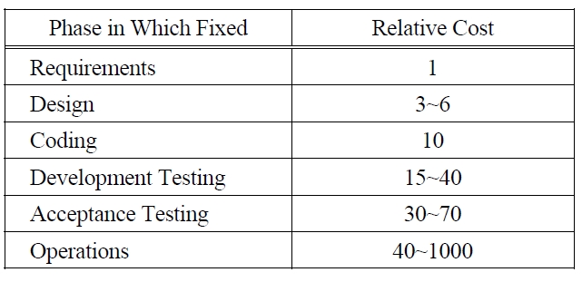
In complex systems, it is important to identify and stabilize the requirements as early as possible in the process. Otherwise, inevitable changes will cause disruption of the product development schedule, increase of costs, and failure to meet the expected system quality. Table 1 shows the relative costs of fixing requirements defects in different phases of a project. Whatever it may cost to do things right in the requirements phase, it may be 3 to 1000 times more costly to fix later.
[Table 1.] Relative Costs of Fixing Requirement errors (Gause and Weinberg, 1989).

Relative Costs of Fixing Requirement errors (Gause and Weinberg, 1989).
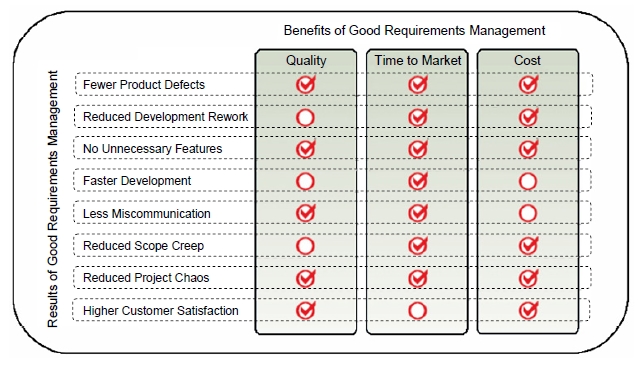
Similarly, Table 2 shows that return on investment (ROI) from practicing good requirements management is substantial, in terms of its results and benefits.
[Table 2.] ROI from practicing good RM (SERENA, 2011).

ROI from practicing good RM (SERENA, 2011).
[Table 3.] Investing in Requirements Accelerate Development (Blackburn et al., 1996).
Investing in Requirements Accelerate Development (Blackburn et al., 1996).
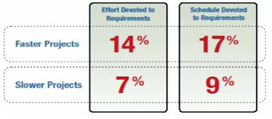
Finally, a European study by Blackburn
With respect to managing requirements change in software development, the requirements can be broadly categorized into volatile (requirements that are likely to change), and non-volatile requirements (stable ones) (Sommerville, 2007; De Lucia
A requirements change normally begins as a request, either formal or informal. Informal change requests need to be checked and controlled as far as possible as it leads to many problems due to inadequate allocation of schedule and manpower to manage those changes. A formal change request needs to be documented from the beginning. A change request has many attributes apart from the requested change itself. Among the important attributes for a change request are type of change < add, delete and modify> (Strens and Sugden, 1996; McGee and Greer, 2009), the importance of change (O’ Neal and Carver, 2001), the reasons and justification and the source of change (Nurmuliani
Once the change request is received, the next important activity is to assess the impact of implementing this change. This is popularly known as impact analysis. Conducting impact analysis helps answer many questions related to the impact of implementing this change. Among the important aspects are, when in development cycle the change needs to be implemented (Ramzan and Ikram, 2006; Imtiaz
One of the main techniques to do the impact analysis is the use of traceability matrix. A traceability matrix represents the dependency relationships between different requirements and also across different artifacts. This dependency relationship can be of different types like ‘dependent,’ ‘ related.’ There are different types of traceability matrix depending on the level of details it works on, the type of information it stores, etc. (Ibrahim
To come up with the traceability matrix for a project is a major task. The core of this issue is to build the dependency relationship between different entities and artifacts. For relatively small projects it may be feasible to build these relationships manually, but for large complex systems, we need some level of automation (Ibrahim
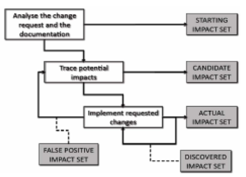
Once the impact analysis is conducted using the traceability matrix, a candidate impact set is obtained which includes all the artifacts and entities affected directly or indirectly by the proposed change. It shall be kept in mind that this impact set is not always accurate in the sense that it may not be able to include all the possible artifacts and entities, and accordingly some of them might be left out (
The results of impact analysis is further studied by employing cost benefit analysis which not only considers the technical implications of change but also other aspects like management, administrative, cost/budget and project schedule (Imtiaz
It is also recommended that there be a clear process and change control body who takes care of the entire change management process instead of change creeping in from anywhere with no proper control on them. This may adversely affect the schedule, cost, and the final quality of the software product. The concept of having an independent
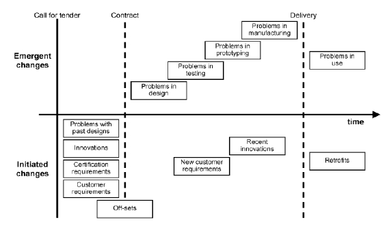
General engineering changes during a system’ s lifecycle have been studied intensively in the last decade. A comprehensive review has been reported recently by Jarratt
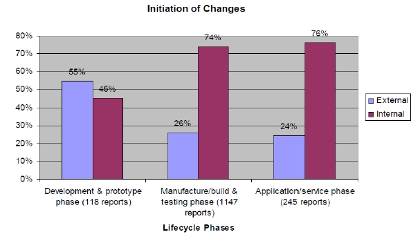
As seen in Figure 9, the sources of changes throughout the design process are numerous, and can be emergent (i.e. arising from the properties of the system itself), or initiated (for improvements, enhancements, or adaptations of the system). The initiation source can be internal (operational experience, manufacture/ assembly, production, build), or external (customer, supplier, contractual), with changes in customer requirements playing a substantial role (Table 4).
[Table 4.] Initiation of changes. From Ahmed and Kanike (2007).

Initiation of changes. From Ahmed and Kanike (2007).
Eckert
With innovative systems, changes are much more likely to occur since everything is fuzzy, particularly requirements, at the front end. This is particularly so in hybrid systems governed by both technology push and market pull, as in many emergent energy systems. In theses cases, the best strategy is to isolate the innovation process within R&D laboratories, where “organized chaos” could be controlled and maintained, until new systems (ideas, materials, processes, etc.) are fully developed and successfully tested.
As noted by Jarratt
Keller
In parallel, Koh and Clarkson (2009) presented a modeling method that aims to manage the effects of change propagation, and applied the method to the design of a jet engine fan. The method uses a matrix-based approach to model the dependencies between the solution alternatives, the potential change propagation brought about by the solutions, the affected product attributes, and the resources needed to carry out the change work. The method allows engineers to trace critical change propagation paths and manage them, and hence appears to be suitable for assessing solution alternatives during preliminary design and exploring the design space in the right direction.
Lemmens
Tracking changes can always give an engineer valuable experience in designing future products. However, this approach is “
Qureshi
The Design For Variety (DFV) method uses product platform architecture to provide a structured approach to reduce the amount of redesign effort for future generations of a product. For large projects, system architecture can be used to break down the design into smaller subsystems at each level of the design hierarchy (Hintersteiner, 2000). The DFV has the advantage of being a simple and inexpensive technique to determine potential design changes. The methodology
Peterson
Establish and foster open communication between designers and customers.
Develop and explicitly write down a complete list of design requirements..
Analyze the list of requirements to identify which requirements are likely to change and which are stable.
Predict future market/ customer needs and requirement changes.
Use an iterative approach. Quick turnover of designs and prototypes provides a method for testing requirements and discovering unanticipated ones.
Build flexibility into the design by selecting product architectures that tolerate changing requirements. This can be achieved by over-designing components that are likely to change to meet future needs.
Information about design freezes is especially important when working in a team. Recognizing the dependencies between parts and acknowledging which parts may be frozen can avoid inadvertent changes to the overall design.
Some of the methods developed for software engineering to assess the impact of a design change can be applied to engineering systems with some adaptation. As noted by Peterson
A couple of models used in software engineering consider changes in evolutionary software development (Schach and Tomer, 2000; Rajlich, 2000). However these models are not appropriate for engineering systems design where component interfaces are not as explicit and involve more than just information transmission. Generally, these programs only identify the immediate implications of change within the immediate sub system and are not capable of exploring the consequences of change propagation through complex systems with different mechanical interactions (Keller
An important concept that should be carried over from software to engineering systems is the adoption of a socio-technical approach which contends that communication problems can be reduced if all stakeholders are involved in all phases of the design process.
The idea of guessing future changes in software (
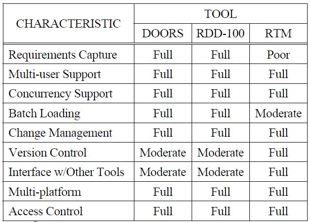
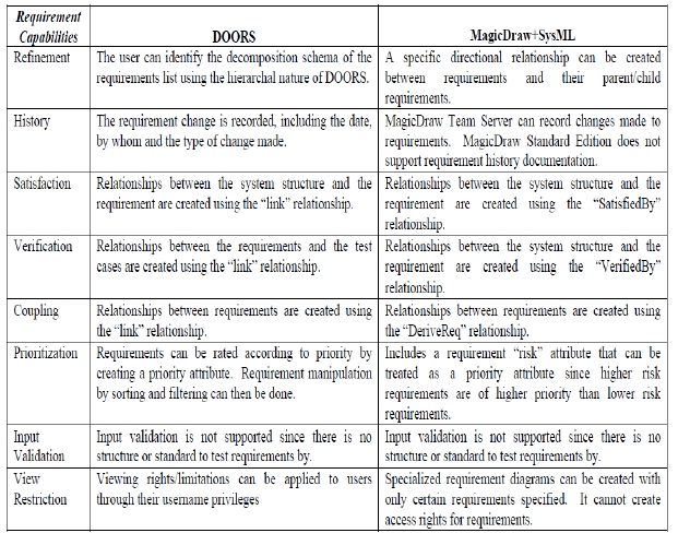
For both software and engineering systems, commercial software tools are available to handle RM. Some of these tools are compared in Table 5 and Table 6.
[Table 5.] RM Commercial Tools (Uspenskiy 2004)*.

RM Commercial Tools (Uspenskiy 2004)*.
[Table 6.] RM Commercial Tools (McLellan et al. 2010)*.

RM Commercial Tools (McLellan et al. 2010)*.
Since requirements development and management are among the most important activities in any software or engineering system project, efforts towards improving these two tasks can always increase and accelerate the ROI. According to the “garbage in, garbage out” rule: If the requirements are not “good” and “properly managed,” all subsequent efforts will only help design, make, and market the wrong unneeded product faster.
The analysis of the mentioned literature revealed that RE in product engineering is mostly restricted to the early phases of the development process. During the late phase, RE does not seem to play a substantial role. Most of these approaches state that the customer plays a central role during the entire development process. The type and degree of customer integration into the development process varies. The integration of the customer into the process of requirements elicitation is emphasized, but not in later phases.
RE is a well-established discipline in software development. This is clear from the many textbooks that have appeared on the subject and the many courses in curricula of various software engineering programs. In contrast, there are no books dedicated to this subject for designing engineering systems. A special journal issue of

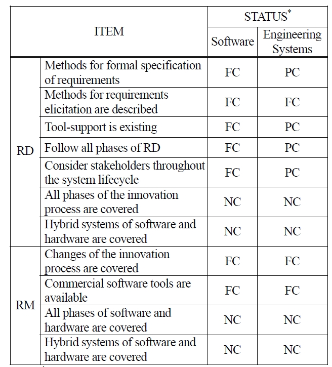
Comparing the Degree of Achievement of Various RD and RM Tasks in Software and Engineering Systems.
Following is Table 7 compares the degree of achievement of various RD and RM tasks in software and in engineering systems.
Both software and engineering systems lack the coverage of RD and RN in complex innovative and/ or hybrid applications.
As seen also in the Table, RD and RM are applied in a structured way in software systems, whereas a few areas are still under-developed for engineering systems; further research in that direction is needed.