Utilizing three-dimensional (3D) computer aided design (CAD) for product development is now the main stream in the field of manufacturing in the recent days. In the field of industrial engineering as well, there are favorable movements in the utilization of 3D CAD for 3D simulation, because it enables pre-production activities to be done in much less amount of time. These 3D simulations are utilized as versatile method, verifying various aspects such as fragility analysis of parts or products, production line designing, facilities designing, or worker arrangements (Grieves, 2006; Yin
As for assembly type manufacturing as well, there is an increasing demand in the use of 3D simulations for the verification of each assembly work, regarding its assembly sequence, parts layout or process planning. However, an assembly work naturally has a fluid process, since several workers cooperate to build a finished product from multiple parts and components, it requires huge quantities of manually input data - using computer mice or motion capture apparatuses - to virtually reproduce workers’ movements and paths. This method can only propose a limited number of possible alternatives, although the simulation itself takes lots of time, cost and labor (Fox, 1986). Therefore, if there is a device to generate 3D simulations without judgment by human from minimal required information, it would shorten the lead time for product development and pre-production and thus would allow flexibility when design alterations arise.
This paper discusses what pieces of information are minimally required in order to generate 3D simulations for assembly work. Furthermore, it presents a new mode of expressing a 3D assembly work for creating 3D computer graphics (CG) animations. A general creation outline will also be described later in the paper. This paper focuses on the creating 3D CG animation of assembly works which workers use only their both hands. In this paper authors consider “running 3D simulation of an assembly work” as “gaining 3D CG animations of an assembly work through the virtually reproduced computer manikin on the display” as shown in Figure 1. A computer manikin is a model of a human in a virtual space to evaluate the products or workplaces.
2. NECESSARY INFORMATION FOR EXPRESSING AN ASSEMBLY WORK AS 3D CG ANIMATION
The assembly work 3D CG animation which this paper would like to create is of a work conducted by computer manikins, to build a finished product by moving parts and components, in the virtual space on the display. The first discussion is on what the minimal required information is to create the 3D CG animation for it.
In order to put the 3D CG into animation, the information on what objects exist, where and how should be acquired. In short, these are existence of “objects” and location and posture or “objects.” If locations and
postures are set each scene, the movement of objects can be described.
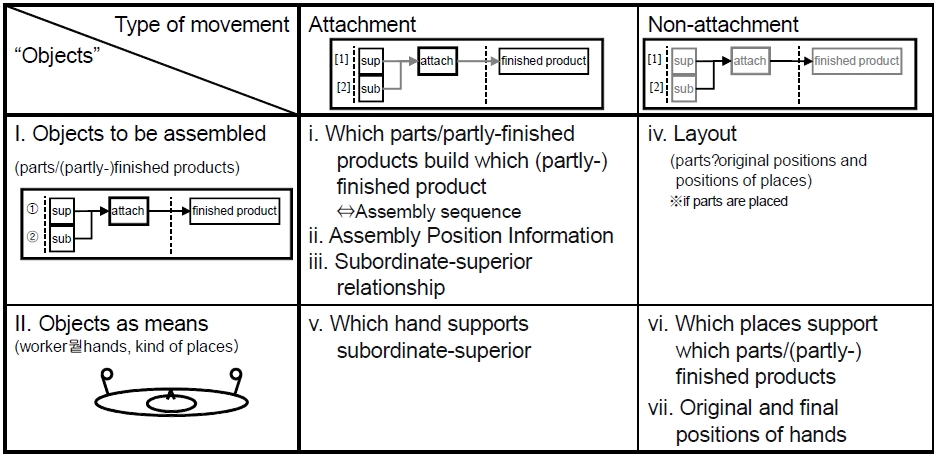
The next discussion is on what information is necessary for the creation of an assembly work 3D CG animation. An assembly work possesses two features: I. Parts are assembled to build a finished product. II. The work is conducted by workers with assistant tools. Therefore, objects in a 3D CD animation can be classified into “objects to be assembled” and “objects as means.” In addition, each movement is categorized either as attachment work or as non-attachment work. Through this thought, it was clarified that 7 information are necessary as shown in Figure 2. These are i. Which parts build which (partly) finished products, ii. Assembly position information, iii. Subordinate-superior relationship (a position of superior parts are fixed, and subordinate parts are moved to superior part when attachment), iv. Parts’ original position and places as layout, v. Which hand of a worker supports subordinate or superior, vi. Which place support parts/(partly-) finished products, vii. Original and final position of a worker’s hands. The information will be specified in following chapters.
2.1 Necessary Information for Expressing 3D CG Animation
In order to express an “object” in 3D CG animation, it is necessary to obtain two pieces of information as shown in Figure 2. One is modeling information of the “object”, and the other is where and how the “object” exists. The first refers to the size and shape; the latter, the position and angle of the “object.” What is presented as an “object” here refers to any modeled material body involved in the course of the work. Therefore, in the virtual space, modeled parts, partly-finished products, tables or workers’ hands are all defined as “objects.” These objects can be put into 3D CG animation when the information on their positions and angles are provided.
When specifying the location of an “object”, the position coordinate and angle coordinate must be listed. The point that gives the object a specific coordinate is called “center point”, and generally it is the most ideal that the center point and the gravity center correspond. The location of an object is the location of the center point of the object, and the movement of an object is equal to the movement of the center point of the object. An object revolves around its center point.
2.2 Features of an Assembly Work 3D CG Animation
Next consideration is on how to specify an object’s position and angle coordinates. Before considering it, the features of an assembly work should be considered. An assembly work is defined as: “a work in which workers assemble necessary parts to build a finished prod
uct.” Thus in assembly work, separate parts are attached in order and eventually, they turn into a finished product by the hands of workers. When two or more parts are attached, a partly-finished product is produced, and one attachment work reduces the total number of parts/partly- finished products. In other words, the number of attachment works a work includes is calculated as “[number of parts]-1” times, through which parts turn into a finished product.
As a matter of course, parts do not move themselves to turn into a finished product, so the attachment works must be done by workers.
Consequently, when deciding an object’s position and angle coordinates of an assembly work in 3D CG animation, two characteristics described as follows must be fulfilled: 1) Parts are assembled to build a finished product at the final stage, 2) Workers move and attach the necessary parts and partly-finished products with jigs, tools and places. In other words, information about objects to be assembled and objects as means (i.e., workers, jigs, and tools) are necessary to create an assemble work 3D CG animation.
2.3 Necessary Information for Creation of an Assembly Work 3D CG Animation
Here a step-by-step approach to specify the necessary information to describe an assembly work, fulfilling the required characteristics stated formerly, should be taken.
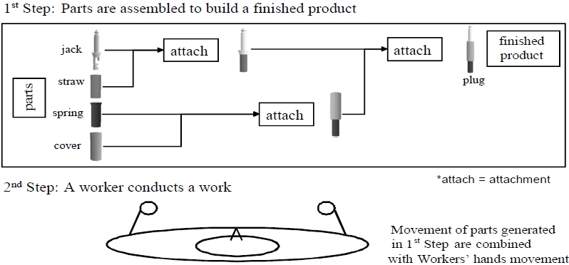
As the first step of 3D CG creation, since parts must turn into a finished product, a 3D CG animation in which parts get together by themselves to build a finished product is created, as in Figure 3. The second step concentrates on the workers’ movement to assemble the parts by moving and attaching them.
This two-step approach to an assembly work makes it easier and more practicable to create a 3D CG animation. Necessary information for each step will be discussed and specified next.
2.3.1 Necessary information about objects to be assembled
First of all, the discussion is on what information must be acquired to create a 3D CG animation, in which parts get together to build a finished product. The necessary information regarding attachment must include ‘which parts build which partly-finished products (or finished products)’. This describes the combination of two parts/partly-finished products and a product (partlyfinished product/finished product) built as a result of their attachment. The number of these attachment works is subtracted 1 from “number of parts”, and it composes an ‘assembly sequence.’ In order to create a 3D CG animation of an assembly work, a sequence must be executable and must not fail to build a finished product. “Executable” here means “One attachment does not prevent other attachments.”
Next, it is necessary to decide ‘subordinate-superior’ relationship between parts/partly-finished products. An attachment work is usually achieved by holding one of the parts/partly-finished products upright when the other moves directly toward it once the location of the former is identified. The one hold upright is to be called “superior”, the other “subordinate.” By deciding which part/partly-finished product of the two at an attachment work functions as superior/subordinate, the information on parts’ subordinate-superior relationship can be acquired.
Considering the actual movements of parts/partlyfinished products at each attachment work, based on the two pieces of information secured above, superior is hold upright at one location, a subordinate identifies its destination and moves until the attachment is completed. Correspondingly, the locations, ‘to hold the superior upright (assembly position, ASP)’, ‘from which the subordinate start moving (approach position, APP)’, and ‘where the attachment of the two is completed (OFFSET)’, must be specified. The 3 pieces of information are generically called “assembly position information.”
When an attachment completes, the discussion on parts’ center points must not be left aside. An attachment work attaches a subordinate to a superior parts/partlyfinished product, and forms a change: a newly built (partly-) finished product. If the pre-attached two parts continue to possess their center points, a newly built product should logically possess two center points. In
reality, an object can possess its own center point, thus it is necessary to integrate the two center points into 1 once the attachment occurs. In other words, the act of integrating the two center points can express a generation of new “object” as a result of one attachment work, in which two parts are involved. Here, the center point discussion concludes by eliminating the subordinates’ center points. This means the center point coordinate of the newly built product after the attachment corresponds to the superior’s center point coordinate.
Non-attachment works which arise alongside the attachment works also hold meaningful information for 3D CG animation creation. Each part exists elsewhere in one place before the attachment work occurs. And after attachment the built product whether they finished or partly-finished should be placed again another place. Corresponding each location, parts’ original position, temporary placing position, and final storing position for the finished products must be secured. These locations can be described as ‘layout’ information altogether.
By adding the pieces of information discussed above to the parts’ modeling information, a 3D CG animation, in which parts are attached to build partly-finished products and finally a finished product, can be created.
2.3.2 Necessary information about objects as means
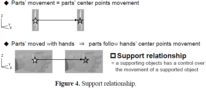
As the second step, necessary information for creating modified 3D CG animations in which workers conduct the work and turn parts into products must be considered. The underlying rule that workers’ hands move parts/partly-finished products must be taken for granted before starting the discussion. The rule presents the idea that an “object” has an influence on another “object.” Based on that rule, “support relationship” must be defined. Any part/(partly-) finished product is given supportive force to be present in the workshop, i.e. by worker’s hands, tables or other material bodies. “Support relationship” can be thus defined as “relationship in which a supporting material body has a control over the movement of the supported object.” Under this relationship, when the supporting “object” moves, the supported “object” must follow its movement. Figure 4 shows the concrete example of support relationship between a part and a hand. A center point of a part must follow a center point of a hand under this relationship.
Since the definition of the support relationship is settled as above, now the discussion can move on to the next stage; what information should be gained to create a 3D CG animation of workers attaching parts. First, the information on how a worker handles parts, namely in an attachment work, ‘which hand of a worker supports the superior or the subordinate’ must be clarified. Thus, in addition to the assembly information, ‘original and final position of left and right hand’ and ‘original, temporary and final position of a part/(partly-) finished product’ must be specified. The latter means which places support which parts/(partly-)finished products.
As a general idea, the information on the second step “support relationship” can be added to the first step parts’ movements to realize a combined animation of workers conducting attachment works. The only necessary information left is regarding original positions of hands and placing/storing positions.
3. A NEW MODE OF EXPRESSING AN ASSEMBLY WORK 3D CG ANIMATION
This chapter proposes a new mode of expressing assembly works, based on the 7 necessary information for 3D CG animation expression discussed in the preceding chapters. First, arbitrary scenes in an assembly work are expressed statically, and these scenes change
to the following scenes reflecting the actual assembly work. This leads to a realization of expressing sequential flow of an assembly work.
An arbitrary scene in an assembly work has only to express the existence of “objects”, ‘where and how they are’, and ‘supporting/supported by what other objects’. These aspects can be expressed with 3 features: 1) modeling information, 2) position and angle, and as pointed out and defined in this paper, through the characteristics of assembly works, 3) support relationship.
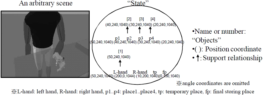
A scene can be described as shown in circles in Figure 5. A circle contains ‘name of “object”’, ‘coordinate’ and ‘arrow.’ In Figure 5, name of part/partly-finished product is described as a number. A coordinate of objects is described in a parenthesis below its object name (angle coordinates are described same style, then they are omitted in Figure 5). An arrow shows support relationship (supporting object at the start/supported object at the end). The scene expressed here is referred to as “state”. showing support relationship
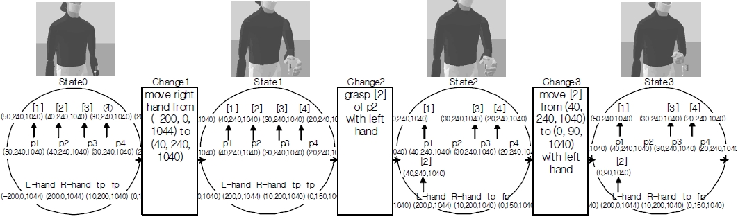
Any arbitrary scene in an assembly work 3D CG can be expressed as “state”. An assembly work can be expressed as sequential flow by changing the “state” from one to following another as shown in Figure 6 (angle coordinate are omitted). Between the “states”, there must be a “change” arisen. When the “changes” are reflected in the description, a sequential assembly work can be expressed as linear sequence. This linear flow is referred to as “state/change transition diagram (SCTD)” (Shinoda and Niwa, 2000, 2001, 2002, 2004, 2005a, 2005b).
4. ALGORITHM FOR GENERATING AN ASSEMBLY WORK 3D CG ANIMATION WITHOUT JUDGEMENT BY HUMAN
The SCTD presented in the previous chapter contains all the necessary information for expressing an assembly work as 3D CG animation. In other words, if it is possible to produce a SCTD from the 7 necessary information as discussed in chapter 2, it should be also possible to create an assembly work 3D CG animation. The general outline for the algorithm which generates SCTD is as follows:
(1) Specify an assembly sequence in an assembly work, also specifying the parts/partly-finished products used in each attachment, and the (partly-) finished products built as a result.
(2) Clarify assembly position information for each attachment, and specify positions and angles of each part/(partly-)finished product.
(3) Specify the layout by deciding where parts and products are placed before and after an attachment.
(4) Once location of each part/product is secured by step (3), identify and clarify the support relationship between the “objects.”
(5) Review the balance of the “objects” to make sure each “State” has equal or similar status in a work, make an adjustment, and specify each existence, position, angle and support relationship. This completes the description on the “states” in the Diagram.
(6) Create “changes” by listing the differences between present and previous “states.”
Following the procedure above enables generation of a SCTD from minimal necessary information. By converting the data, it enables creation of an assembly work 3D CG animation (Shinoda
5. EXAMPLE OF THE APPLICATION OF THE ALGORITHM
This chapter shows the example to apply the algorithm to an actual product which is main parts of printers named drum cartridge. This drum cartridge consists of 38 parts, then, 37 attachments are needed to get a finished product.
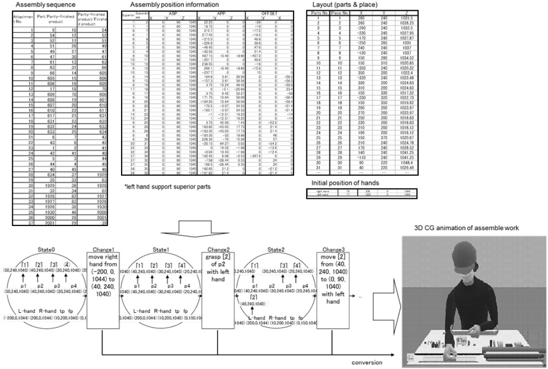
Figure 7 shows the outlines of the application. First, the modeling information was created from 3D CAD information. Next, an assembly sequence which assures the 38 parts become the finished product through 37 attachments was created. And based on the information, Subordinate-superior relationship and assembly position information was prepared for each attachment. In this time workers support superior parts with their left hand were defined. These informations are included in assembly position information in Figure 7. And next layout which includes parts original positions, positions of places, original positions of hands was prepared as shown in Figure 7. Relationship between parts and places were also clarified. Assembly position information and layout are shown as X-Y-Z coordinate system. From these necessary information, “states” before and after 37 attachments was created at first. And the other “states” could be created by layout information. After that, all “changes” were created from the gaps between present and previous “state”. SCTD could be completed with this processing. Lastly these “changes” were converted to 3D CG animation which workers assemble a drum cartridge was generated. This means a 3D CG animation can be created from only modeling information and 7 necessary information through the algorithm of SCTD.
Assembly sequence is main information among 7 necessary information. Then, when another assembly sequence and other associated necessary information is prepared, we can compare assembly sequences to find out suitable assembly sequence for that products.
In this paper, the author presented what the minimal necessary information is for creating an assembly work 3D CG animation without judgment by human, by focusing on the two features of an assembly work in terms of its structure: 1) Parts are assembled to build a finished product, 2) The work is conducted by workers with assistant tools. Furthermore, a new mode of expressing an assembly work 3D CG is proposed as well as the outline of its automatic generation algorithm. By creating an assembly work 3D CG without judgment by human, it has a possibility to provide benefits such as shortening lead time for product development and preproduction.
This paper shows only way of creating a 3D CG animation of assembly work from an assembly sequence. The method of generating plural 3D CG animation from plural assembly sequence is required to compare assembly sequence and find out better assembly sequence for that product.
And also, this paper specifically deals with manual assembly works, although actual assembly works utilize various jigs and/or tools. The author hopes to develop and establish algorithms for generation of such assembly works as future research.