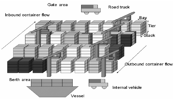
Container terminal is a complicated logistical system that performs various interrelated handling activities for container transfers among vessels and hinterland transportation modes such as trucking and rail. The four basic operations in a container terminal include: discharging inbound containers from vessels; loading outbound containers onto vessels; receiving outbound containers from road trucks or trains; and delivering inbound containers to road trucks or trains for hinterland transportation. Figure 1 shows a yard configuration and container flows in a container terminal. The storage yard consists of blocks. Each block consists of 30?40 bays, each of which consists of 6?0 stacks (rows).
The storage rules for inbound containers are relatively simpler than those for outbound containers be-
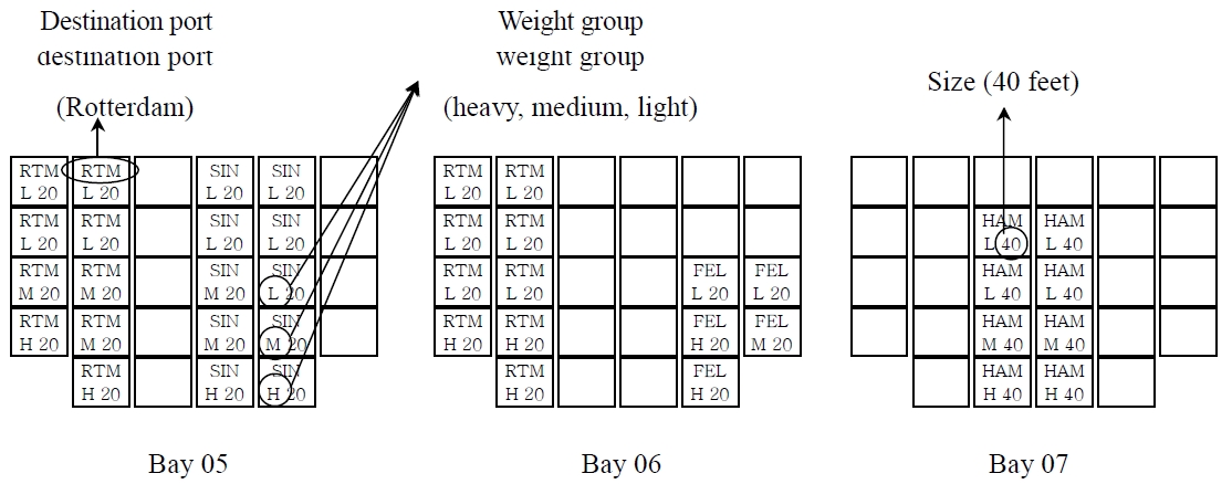
cause there are fewer constraints to satisfy for inbound containers than for outbound containers. Outbound containers are loaded onto a vessel, and the storage locations of a specific type of outbound containers are constrained by a stowage plan as illustrated in Figure 2 (Park, 2003). The plan shows cells for three bays, for each of which the type (group) of outbound containers to be loaded is specified. The type (group) of containers is defined by the destination port and the size.
For efficient loading operation, several principles are widely accepted with regard to space planning. First, yard-bays that are assigned to a container-ship should be located near the berthing position of the corresponding ship (nearest location principle). Second, containers must be placed at locations that can avoid congestion of the yard cranes and internal trucks (least congestion principle). Thus, containers bound for the same vessel are usually distributed over several blocks.
Third, containers of the same group must be located close to each other in either the same bay or in adjacent bays (concentrated location principle), which is valid only for the indirect transfer systems utilizing both the yard-side equipment (yard cranes or straddle carriers) and prime movers. During the loading operations of containers, containers of the same group are likely to be loaded onto cells that are located close together, as illustrated in Figure 2; thus, they are usually loaded consecutively. Thus, the travel distances of yard cranes can be reduced by placing the containers of the same group in slots that are close to each other. In practice, all the stacks in a yard-bay or in adjacent yard-bays are usually allocated to the same container group. Towards the allocation, all the stacks in a compact area are usually reserved in advance for a specific container group. However, when the size of the reservation is very large, there may be a waste of space, which, in turn, may result in a space shortage for other container groups.
Fourthly, containers must be located in a way that relocations of containers are minimized (least relocation principle). Thus, containers of different groups must not be mixed in the same stack. When containers of different groups are mixed in the same stack, relocations may occur for picking up a container of a group, which is located under the containers of other groups.
Finally, containers must be located so that broken spaces are minimized (minimum broken spaces principle). The amount of broken spaces is measured by summing up the number of empty but reserved slots multiplied by the duration for which the slots remain empty.
Note that the outbound containers include transshipment containers that are discharged from a vessel and loaded onto another vessel. For inbound containers, the first and second principles are popularly used in practice. There may be three hierarchies in decision-making with regard to the storage locations of containers: block selection, bay selection, and stack selection.
Some early studies (Castilho and Daganzo, 1993; Taleb-Ibrahimi
Kim and Bae (1998), Hirashima
Most of the previous studies proposed mathematical models for allocating storage spaces. Dekker
[Table 1.] Configurations and rules to be compared
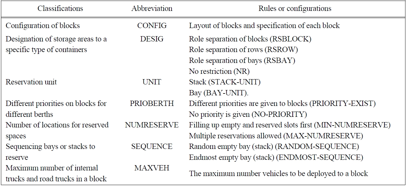
Configurations and rules to be compared
2. PERFORMANCE MEASURES, DESIGN PARAMETERS, AND RULES FOR CONTAINER STORAGES
The productivity of quay cranes (QCs) is one of the most popular performance measures for evaluating container terminals. However, the productivity of QCs is influenced not only by the storage rules but also by many other factors. In addition, the storage rules indirectly affect the productivity of QCs through the efficiency of ship operations. Therefore, the system time of trucks in blocks, the shortage of space in the yard, and the travel time of trucks between QCs and the yard are selected as the performance measures for evaluating the storage rules.
The performance measures are defined as follows. The system time of internal trucks and road trucks implies the total time that these trucks spend at a block beginning from arrival at the block through departure from the same block. It measures the degree of congestion of internal trucks and road trucks at the block and is a function of the service time of yard cranes at the block and the arrival rate of internal trucks and road trucks at the block. The space shortage is another important performance measure of container yards. When arriving containers are not assigned storage space, they have to be moved to an outside yard, which incurs additional costs. The storage locations of containers affect the travel times of trucks. When the QC that discharges or loads a container is far from the storage location of the container in the yard, the internal truck must travel a long distance to deliver the container, which results in a requirement for more internal trucks during the ship operation.
A storage policy or rule may be related to the selection of a block, a bay, or a stack. Here we introduce various storage policies or rules that affect the performance of terminals at strategic, tactical, and operational levels. Table 1 summarizes the rules and configurations to be tested in this paper.
2.1 Strategic Design Parameters-Configuration of Blocks (CONFIG)
Many design parameters of the storage area influence the performance of the transfer operation of the yard crane including: 1) the layout of blocks in the yard; 2) the positions of the transfer points of containers between yard cranes and trucks; and 3) the configuration of each block (the number of bays, the number of rows, and the number of tiers). This paper will address the configuration (CONFIG) of blocks and analyze the effect of different configurations on the performance of the yard operation.
2.2 Designation of Storage Areas to a Specific Type of Containers (DESIG)
For convenience in the inventory control of containers, many container terminal operators pre-allocate some areas in the yard to a specific type of containers. For example, the areas for inbound containers are designated separately from those for outbound containers. Various designations of areas in the yard to specific types of containers are being used including the following.
Role Separation of Blocks (RSBLOCK): Each block is assigned to either inbound containers or outbound containers.
Role Separation of Rows (RSROW): Each block is divided into two parts. One half of the rows in one side of each bay are assigned to outbound containers, while the other half of the rows at the other side are assigned to inbound containers. This policy is usually used for blocks with a large number of rows in a bay and allows the dual-cycle operation of a yard crane in a bay.
Role Separation of Bays (RSBAY): The storage area for each block is partitioned into two sub-areas. Half the bays of each block, which are near the entrance of the block aisle, will be assigned to inbound containers, while the other half will be assigned to outbound containers. In this way, more dual-cycle operations of internal trucks are expected during the ship operation.
No Restriction (NR): There is no restriction on the usage of space. Inbound and outbound containers can be located at any place in the yard.
According to the concentration principle for the storage locations of outbound containers, some area of the storage space is reserved in advance for a specific group of containers. The two most popular reservation units adopted in practice are ‘stack unit’ (STACK-UNIT) and ‘bay unit’ (BAY-UNIT). When the stack unit is used, all the slots in a stack are reserved for containers of the same group. When bay units are used for reservation, all the slots in the same bay are reserved for containers of the same group.
2.4 Different Priorities on Blocks for Different Berths (PRIOBERTH)
This is a block selection rule. When the size of a container terminal is large, some blocks are more favored than others by vessels at a specific berth because of the differing travel distances of trucks from the berth to the positions of containers. Thus, when spaces are available at those blocks, the blocks with a higher priority may be considered first as candidate positions for containers than other blocks (PRIORITY-EXIST). Alternatively, no priority may be given for any block (NO-RIORITY).
2.5 Number of Locations for Reserved Spaces (NUMRESERVE)
NUMRESERVE is related to a block-selection rule. When the storage space for a container group is reserved in the stack unit or the bay unit for a high utilization of space, empty spaces at the reserved stack or bay must be filled first by arriving containers before a new empty stack or bay is reserved for the same container group (Filling up empty and reserved slots first: MIN-NUMRESERVE). However, in this case, all trucks with containers of the same group will be routed to the same block with the reserved stack or bay, which may result in a congestion of trucks. Thus, each block may be allowed to have a reserved stack (or bay) for a container group (Multiple reservations allowed: MAX-NUMRESERVE). In MAX-NUMRESERVE, after a block is first selected by a block-selection rule, if a stack or a bay exists with empty slots that are reserved for the same container group, the stack or bay will be selected for stacking the arrived container; otherwise, an empty stack or bay will be reserved for the container group.
2.6 Sequencing Bays or Stacks to Reserve (SEQUENCE)
The SEQUENCE rule may be a bay-selection rule when the reservation unit is a bay (or a stack-selection rule when the reservation unit is a stack). When a new empty bay or stack is reserved in a block for arriving containers, two types of priority rules can be used: a random bay (stack) (RANDOM-SEQUENCE) or the endmost bay (stack) (ENDMOST-SEQUENCE) among the empty bays (stacks). The endmost-bay (stack) rule selects the empty bay (stack) that is nearest to either end of the block, while the random-bay (stack) rule selects a random empty bay (stack) from candidates.
2.7 Maximum Number of Internal Trucks and Road Trucks in a Block (MAXVEH)
The MAXVEH storage rule is related to block selection. When the storage location is determined for newly arriving containers, those blocks are excluded from consideration for which the total number of trucks that either wait at the block or head to the block is larger than a specified number. The purpose of this rule is to avoid congestion and long waiting queues at the block.
3.1 Performance Measures and Storage Rules
The simulation study evaluated various storage rules by using performance measures, such as the average system time of internal vehicles and road trucks during different types of operation, the average shortage in the storage space, and the average travel distance of internal vehicles. Since there are too many combinations of different storage policies or rules, some basic strategies or rules are selected. Unless explicitly mentioned, these basic strategies/rules were assumed in the experiments:
1) DESIG: There is no dedicated area for either inbound or outbound containers in the container yard (No Restriction).
2) PRIOBERTH: A container can be stored in any block in the yard without consideration of the block priority (NO-PRIORITY).
3) UNIT: A stack is reserved for containers of the same group (STACK-UNIT).
4) NUMRESERVE: A new empty stack is reserved for a container group after the previous stack for the same container group becomes completely full (MIN-NUMRESERVE).
5) MAXVEH: The number of vehicles in each block is not considered as a condition for selecting candidate blocks.
6) SEQUENCE: The stack is selected randomly in a block (RANDOM-SEQUENCE).
[Table 2.] Different layouts used in the simulation
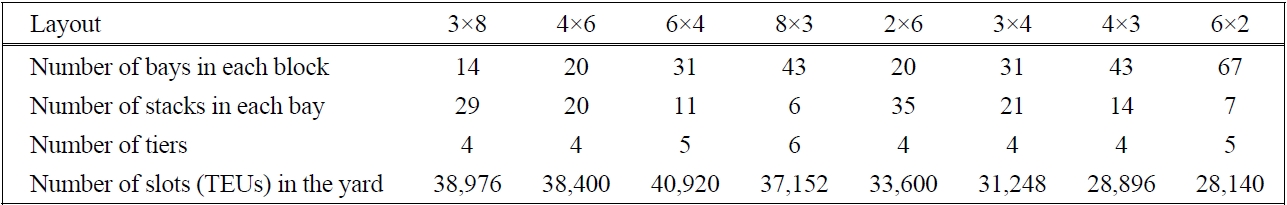
Different layouts used in the simulation
3.2 Terminal Configuration and Input Data Used in the Simulation Model
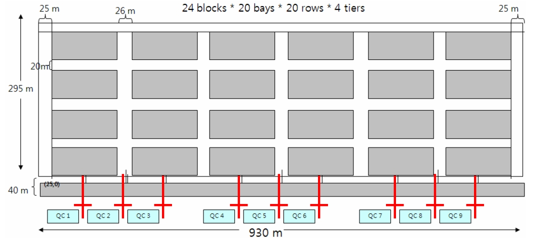
The simulation models in this section are developed in light of the following handling system and operation scenario. The basic models are constructed by considering a terminal with three berths, wherein blocks are laid out in parallel to the quay. Table 2 details the specifications of each layout. There are two groups of yard layout: those with 24 blocks and those with 12 blocks. Figure 3 shows the layout of the former (4×6). Note that the size of yards with 24 blocks was assumed to be (295×930 m), while it was (211×930 m) for yards with 12 blocks. In the consideration of alternative layouts, the aim was to develop layouts that are as similar as possible with regard to the total storage capacity with the proviso that the storage capacity of layouts with 12 blocks was three-fourths of that of the layouts with 24 blocks. The (4×6) and (4×3) layouts are used as the basic models for yards with 24 and 12 blocks, respectively. This means that, if not mentioned explicitly, either of the two layouts will be assumed in the simulation. Each berth has three QCs installed. Each block has two rail-mounted gantry cranes (RMGCs) of the cantilever type with transfer points at both sides of the bays. The empty and loaded gantry speeds and the empty and loaded hoist speeds of RMGCs were set to 120, 30, 80, and 40 m per minute, respectively, and the trolley speed of RMGCs was set to 120 m/min. The time required for an RMGC to release or pick-up a container was assumed to be 10 seconds. It was also assumed that the gantry and trolley movements of RMGCs can occur simultaneously. The upper aisle of each block is assigned for road trucks while the lower aisle of each block is assigned for internal vehicles for which the speed was set to 150 m/min. Five internal trucks were dedicated to each QC.
With regard to input data, data that were collected from Pusan East Container Terminal are used. Raw data, collected from Pusan East Container Terminal, on arrival times of vessels and the number of containers of each vessel were used for the simulation. The arrival times of trucks were analyzed and an empirical distribution of arrival times of trucks was constructed, which was used for generating truck arrival events. In the simulation model, vessels arrive at the terminal for 46 days. The number of vessels that arrive during the period is 74. The average, maximum, and minimum numbers of load-
ing containers per vessel are 435, 1,379, and 12, while those of the containers that are discharged are 512, 1,737, and 10, respectively. The arrivals of road trucks for containers of each vessel are generated by using the distribution of truck arrivals, which spans the time-interval that begins seven days prior to the arrival of the vessel and continues until seven days after the departure of the vessel.
Statistics were collected for 30 vessels that arrived between the 17th day and the 28th day to remove data-points during the initial and final transient periods. Thus, this is a steady state simulation study. The eM-plant software (Tecnomatix, Plano, TX, USA) was used for the development of the simulation program. For each statistic in the simulation results, the average of the results from five simulation runs was obtained and listed in tables. Statistical tests have been conducted to compare the performances of the system with different rules or configurations. Statements in the following texts are based on the statistical tests. Because of the limitation in the number of pages, however, the test results were omitted. In some cases, simulation runs were conducted in a larger number than 5 for the statistical test purposes.
3.3 Comparison of the Performance across Different Layouts (CONFIG)
It is expected that the length and the width of a block affect the cycle time of RMGCs significantly, because they determine the gantry and the trolley travel times of RMGCs. Also, the numbers of vertical and horizontal aisles affect the travel time of trucks. This subsection tests the impacts of these design parameters on the performance of the yard. Table 3 shows the longest travel time of RMGCs in the gantry and trolley directions. Since the two RMGCs are deployed in a block, one half of the block length was considered to be the longest length in the gantry direction. The value of the shape factor of each yard layout configuration, which is the longest trolley travel time divided by the longest gantry travel time, is provided in Table 3.
[Table 3.] Longest gantry and trolley travel time of RMGC in a block
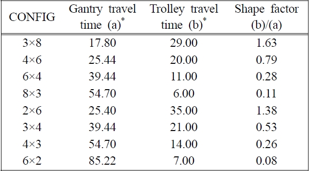
Longest gantry and trolley travel time of RMGC in a block
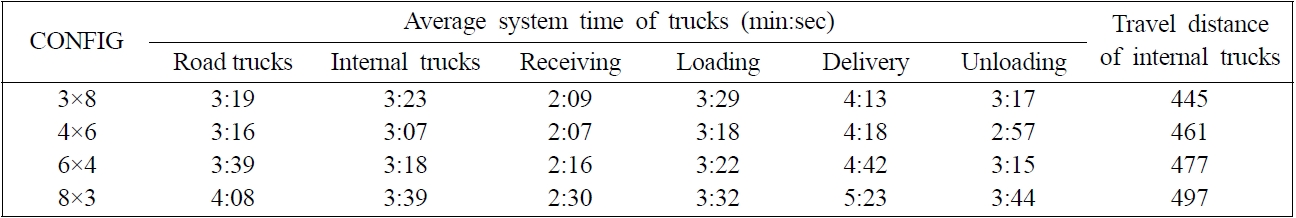
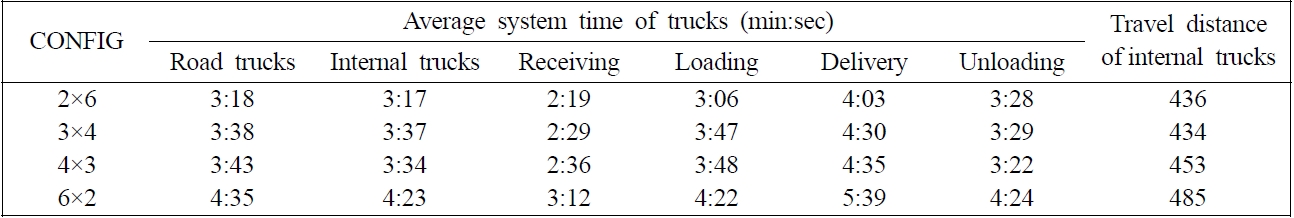
Tables 4 and 5 list the average system time of road trucks and internal trucks and the average travel distance of internal trucks for different block configurations. Among the layouts with 24 blocks, the average system time of road trucks and internal trucks is the shortest in the (4×6) layout; the next shortest is in the (3×8) layout. Note that in the (4×6) layout, the difference between the longest trolley and gantry movement times is the smallest. The difference is the second smallest in the (3×8) layout. However, in the case of loading and unloading operations that require less frequent gantry travels, the (6×4) layout, which has 11 stacks in a bay, outperformed the (3×8) layout, which has 29 stacks in a bay. Also, note that the average system time during the receiving operation is the shortest, and the corresponding figure during the delivery operation is the longest because of the re-handling that is required for picking up an inbound container. The average travel distance of internal trucks is the shortest in the (3×8) layout in which the number of bays in a block (the length of a block) is the shortest. The results of the layouts with 12 blocks are

Average system time and travel distance for different CONFIG parameters in layouts with 24 blocks

Average system time and travel distance for different CONFIG parameters in layouts with 12 blocks
similar to those with 24 blocks.
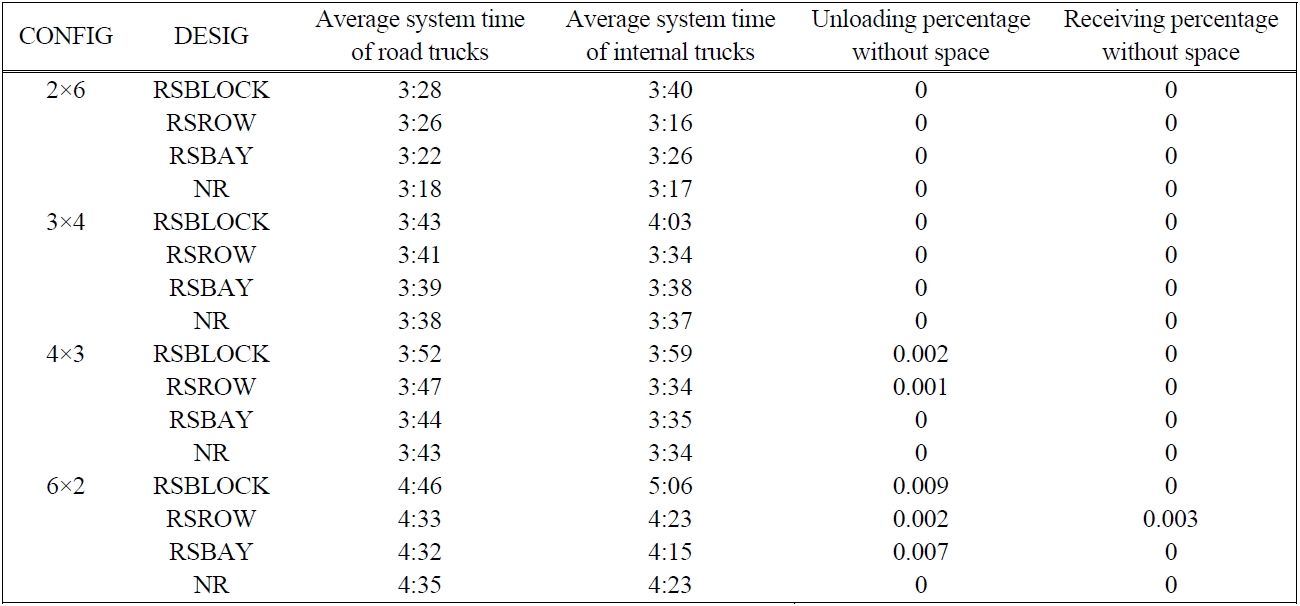
3.4 Comparison of the Performance of the DESIG Storage Rules
In some terminals, the types of containers that can be stored at a specific area may be restricted for the convenience of the management of containers. It is expected that this restriction will affect the productivity of the yard handling system significantly. Also, a tighter restriction may result in a higher possibility of the storage space shortage. Tables 6 and 7 show that the rule of RSBLOCK, in which a block can receive only outbound or inbound containers, yields the longest average system time of both road and internal trucks. The average sys-
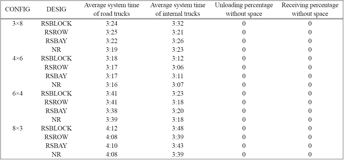
Average system time and travel distance for different DESIG parameters of CONFIG with 24 blocks
tem time of internal trucks was shorter in the cases of RSROW and NR than in the cases of RSBLOCK and RSBAY. The differences are caused by RSROW and NR which tend to distribute the traffic of trucks over a wider area than RSBLOCK or RSBAY. The differences become more apparent in the layouts with 12 blocks than in the layouts with 24 blocks because, in the latter case, the total handling capacity (the number of yard cranes) is smaller than in the former case.
Since the total storage capacity in the layouts with 12 blocks is smaller than that in the layouts with 24 blocks by a quarter of the total capacity, some containers that are unloaded or received cannot find storage locations in the (4×3) and (6×2) layouts. Note that the total storage capacities in the (4×3) and (6×2) layouts

Average system time and travel distance for different DESIG parameters of CONFIG with 12 blocks
are smaller than those in the (3×4) and (2×6) layouts. Also, in the (6×2) layout, because the number of tiers is greater than in the other layouts, the amount of broken space must be larger than that in the other layouts. Note that for the case of 12 blocks, RSBLOCK, RSROW, and RSBAY, which consider fewer candidate stacks than NR, exhibit more shortage than NR.
3.5 Comparison of the Performance of the UNIT Storage Rules
When an empty bay is reserved for a type of containers (BAY-UNIT), more empty space must be reserved than when an empty stack is reserved (STACK-UNIT). Thus, different units of reservation may give different levels of space requirements, which is the main issue of the following experiment. Tables 8 and 9 provide the simulation results that compare the performance of the two reservation units, BAY-UNIT and STACK-UNIT, under different block configurations. First of all, the BAY-UNIT reservation results in a significant shortage
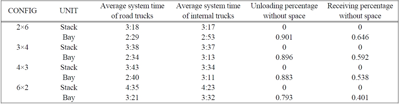
Average system time and travel distance for different UNIT parameters for CONFIG with 12 blocks
in space for both the containers that are received and the containers that are discharged. However, it was found that BAY-UNIT outperforms STACK-UNIT in terms of the average system time of trucks and vehicles. This can be explained as follows: because BAY-Unit provides a greater reservation area for containers of the same group, fewer gantry movements of RMGCs are expected, which results in shorter operation times per container on the part of RMGCs, hence the shorter system times of trucks at blocks. However, note that the rejection-because of shortage in the storage space-of some containers that are being received may have partially contributed to the shorter system times of trucks in the case of BAY-UNIT.
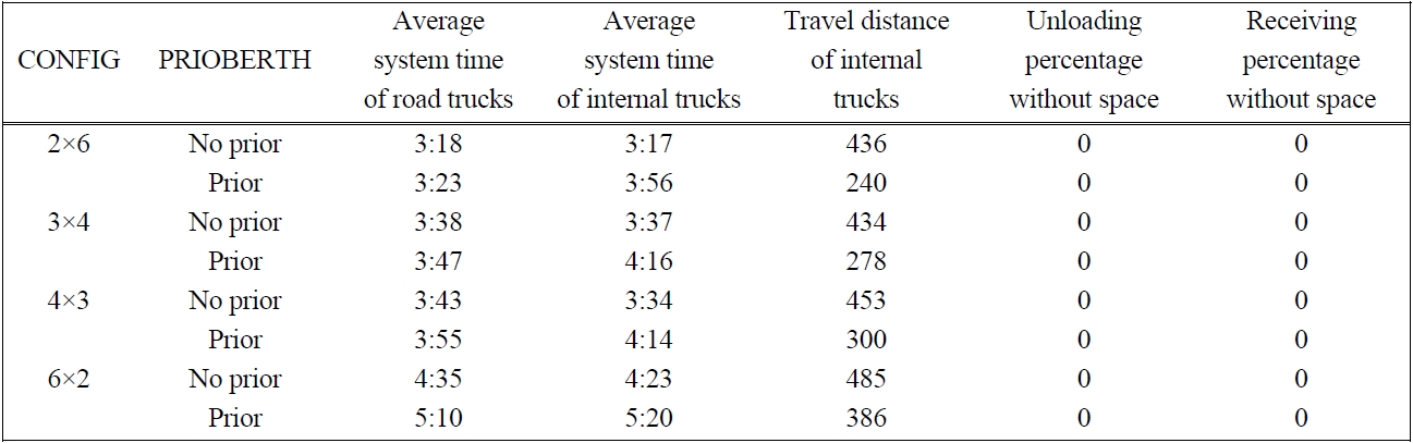
3.6 Comparison of the Performance of the PRIOBERTH Storage Rules
Depending on the berthing position of a vessel, different blocks may have different priorities (PRIORITY-EXIST) for the assignment of storage locations of con-
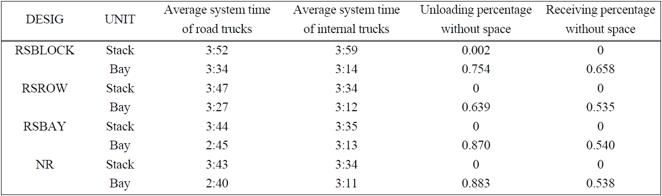
Average system time and travel distance for different UNIT parameters for DESIG with 12 blocks
tainers bound for the vessel in order to reduce the travel distance of internal trucks during the ship operation. Considering the travel distances between blocks and berths for vessels to arrive at each berth, storage blocks are assigned with one of the three different priorities. For each berth, a set of blocks nearer to the berth is assigned a higher priority in terms of the assignment of storage locations for the containers of the vessel. If no space is available in a block with the highest priority, then a block with the next highest priority will be the candidate block.
The simulation results for the PRIORITY-EXIST and NO-PRIORITY rules, in which no priority is applied for selecting blocks, are provided in Table 10 for different layouts. Overall, the average system time of trucks for the case of PRIORITY-EXIST was longer than for the case of NO-PRIORIY, which results from the higher congestion of trucks under PRIORITY-EXIT than under NO-PRIORITY. The difference was bigger in the case of internal trucks than in the case of road trucks because the arrival rate of internal trucks during the ship operation is much higher than that of road trucks that arrive randomly. However, the average travel distance of internal trucks is reduced by applying the rule of PRIORITY-EXIST.

Average system time and travel distance for different PRIOBERTH parameters for CONFIG with 12 blocks
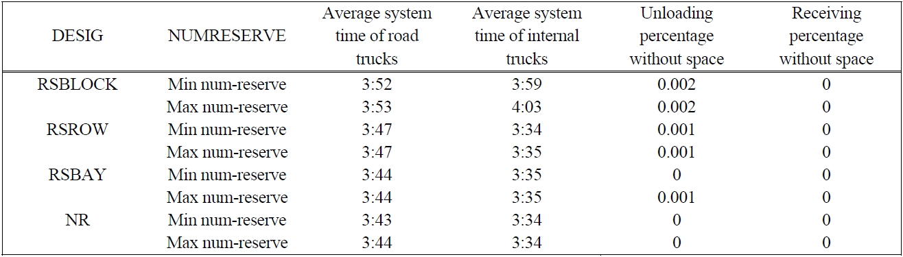
3.7 Comparison of the Performance of the NUMRESERVE Storage Rules
When we have more candidate blocks for the same type of containers, then it is expected that there will be a higher chance to avoid traffic congestion but at the same time a greater storage space requirement. This section compares the performance of MAX-NUMRESERVE and MIN-NUMRESERVE for different rules of DESIG. The results of the simulation study listed in Table 11 do not show much difference between the two rules.
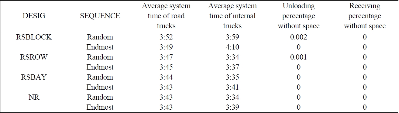
3.8 Comparison of the Performance of the SEQUENCE Storage Rules
When 40 foot containers are located in a block, because they require two slots of 20 ft, it is expected that more candidate positions can be provided when containers are filled from the ends of the block (ENDMOST-SEQUENCE) rather than when they are filled in a random order (RANDOM-SEQUENCE). In Table 12, RANDOM-SEQUENCE and ENDMOST-SEQUENCE are compared with each other jointly with the rules of DESIG in terms of the system time of trucks and the shortage of space. The simulation result showed a small difference in the

Average system time and travel distance for different NUMRESERVE parameters for DESIG with 12 blocks (4×3)

Average system time and travel distance for different SEQUENCE parameters for DESIG with 12 blocks (4×3)
average system time of road trucks, while ENDMOST-SEQUENCE yielded a longer average system time of internal trucks, which resulted from the increased congestion of yard cranes and internal trucks, greater than RANDOM-SEQUENCE. However, RANDOM-SEQUENCE resulted in a greater possibility of space shortage than the ENDMOST-SELECTION rule, because under RANDOM-SEQUENCE, the probability that two consecutive 20 ft bays, which are required for storing 40 ft containers, remain empty becomes lower than in the case of ENDMOST-SEQUENCE.
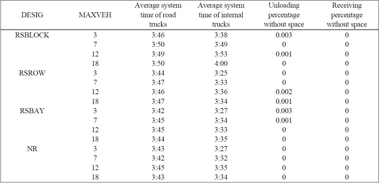
3.9 Comparison of the Performance of the MAXVEH Storage Rules
Because the traffic congestion of vehicles influences the performance of the yard significantly, the rule for locating containers can restrict the number of vehicles (MAXVEH) that are routed to a block. Table 13 compares the simulation results for different maximum numbers of vehicles that are allowed (MAXVEH) per block in various layouts. When MAXVEH = 3, the average system time of trucks is less than that in the other cases, although the difference in the average system time is small. However, when MAXVEH = 3, there is a higher possibility of space shortage than that in the other cases.
Table 14 summarizes the results of the simulation experiments in the form of guidelines for locating containers in the yard.
This paper analyzed storage rules for locating containers in the container yards of 8 different layouts. The 8 layout alternatives were evaluated in terms of the average system time of trucks and space shortage in the yard. The storage rules analyzed included the designation policies on storage areas for specific types of containers (RSBLOCK, RSBAY, RSROW, and NR), priority rules for selecting blocks for each berthing position of vessels (PRIORITY-EXSIT and NO-PRIORITY), and the reservation unit for outbound containers (BAY-UNIT and STACK-UNIT). Either more than one reserved stack (MAX-NUMRESERVE) or only one reserved stack (MIN-NUMRESERVE) may be allowed for a container group. Empty spaces for locating containers may be selected either from the endmost position (ENDMOST-SEQUENCE) or randomly (RANDOM-SEQUENCE).
The following conclusions are drawn from an analysis of the performance through simulation studies on configurations of blocks and storage strategies. The simulation result of block configurations indicates that the

Average system time and travel distance for different MAXVEH parameters for DESIG with 12 blocks (4×3)
[Table 14.] Guidelines for locating containers
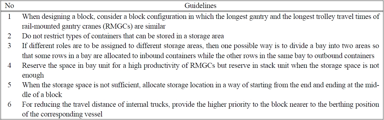
Guidelines for locating containers
yard blocks with the smallest difference between the longest gantry and the longest trolley travel times of RMGCs yielded the shortest system time of trucks. RSBLOCK, in which a block can either receive only outbound or inbound containers, yields the longest average system time of both road and internal trucks. The average system time of internal trucks is shorter in the cases of RSROW and NR than in the cases of RSBLOCK and RSBAY. The RSBLOCK, RSROW, and RSBAY, which have fewer candidate stacks than NR, entail a higher possibility of space shortage than NR. The BAY-UNIT reservation strategy entails a much higher possibility of space shortage than the STACK-UNIT reservation strategy for both the containers that are being received and the containers that are being discharged. However, it was found that BAY-UNIT outperforms STACK-UNIT in terms of the average system time of trucks and vehicles. The average system time of trucks for the case of PRIORITY-EXIST is longer than that for the case of NO-PRIORIY. The difference is bigger in the case of internal trucks than in the case of road trucks. However, the average travel distance of internal trucks is reduced by applying the rule of PRIORITY-EXIST. The MAX-NUMRESERVE and MIN-NUMRESERVE do not show much difference with regard to the average system time of trucks and the average space shortage. Comparison of RANDOM-SEQUENCE and ENDMOST-SEQUENCE revealed a small difference in the average system time of road trucks, while ENDMOST-SEQUENCE yielded a longer average system time of internal trucks. However, RANDOM-SEQUENCE had a higher possibility of space shortage than the ENDMOST-SELECTION rule. When the maximum number of vehicles allowed per block (MAXVEH) becomes small, the average system time of trucks increases. However, the average system time was not so sensitive to MAXVEH. However, when MAXVEH becomes smaller, the possibility of the space shortage becomes larger.