In realizing mobile healthcare services, feature extraction from biomedical signals is very important, and not only is the measurement of signals inconvenient to patients, but also the accuracy of measurement should be higher when the patient is moving [1-3]. The kinds of useable biomedical signals in the healthcare service system include electrocardiography (ECG), blood pressure (BP), body temperature (BT), and photoplethysmography (PPG) [3-5]. The measurable signals in real time in the mobile healthcare system are ECG, PPG, and BT. ECG and BT signals can be acquired in moving patients because the positions of sensors for measuring the signals are near the heart and less affected by noise (motion artifacts) that occur from a patient’s movement. On the other hand, a PPG signal is affected by motion artifacts because the position of a sensor for measuring the PPG signal is a finger or wrist, and the position moves with the patient’s movement, and the sensor is exposed to an external light source. The frequency spectrum band (0.01-10 Hz) of the motion artifacts overlaps the frequency band (0.05-8 Hz) of the PPG signal [4-8]. On account of these problems, it is difficult to remove the motion artifacts of the PPG signal. In the last few years, to address this problem researchers have developed several signal processing algorithms [4, 5]. The suggested methods in their articles are to remove the noise through acceleration sensors and adaptive filters. The methods have shown good performance, but the sensors are very expensive. Therefore, this study suggests a novel PPG signal sensing method as a less expensive way to address the artifact problem. The proposed sensing method uses an light-emitting diode (LED; wavelength, 660 nm or 940 nm) and two photosensors. One photosensor is used to acquire the PPG signal generated from the arterial pulse, and the other photosensor is used to acquire the non-arterial pulse that is assumed to be motion artifacts. In order to reject the motion artifacts that existed in the acquired PPG signal, each of the acquired two signals was used as inputs to an adaptive filter using the normalized least mean square method [9, 10]. In order to evaluate the performance of the proposed method, this study analyzed the results of its signal reconstruction and the heart rate variability by using an adaptive filter in the frequency domain.
II. DESIGN OF PPG SEnSOR and FILTER
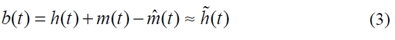
A PPG sensor is a non-invasive medical device based on the Beer-Lambert law [6, 7] described by Eq. (1), and is used to acquire the signal
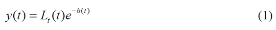
where,
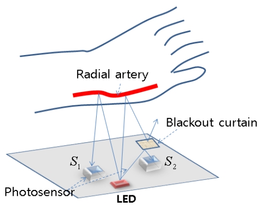
In order to address the problem, this study suggests a novel sensing method and structure as shown in Fig. 1.
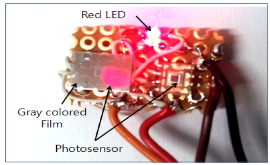
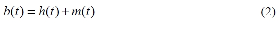
The structure of the proposed sensor device consists of an LED (660 nm), two photosensors (

where,
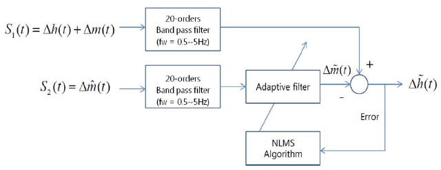
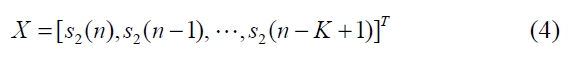
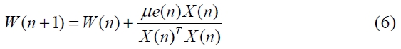
This study suggests that the motion artifact filter be based on the normalized least square algorithm [9] by using the proposed sensor. The suggested method is shown in Fig. 2.
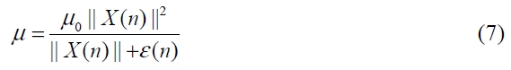
In Fig. 2, we used a band pass filter (BPF) in which the cutoff-frequencies are 0.5 Hz and 5 Hz. The purpose of the BPF is to eliminate high-frequency noise and the direct current (DC) component. The applied adaptive filter used in this study was suggested by Ref. [10] and can be described by the following equations:

where,
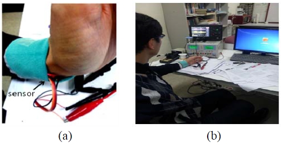
In order to evaluate the performance of the proposed sensor and filter, we have implemented the sensor (Fig. 3) and analyzed the rates of signal reconstruction and heart beat variation by using an adaptive filtering algorithm programmed in MATLAB (MathWorks, Natick, MA, USA). In Fig. 3, the wavelength of the used red LED is 660 nm, and a photosensor to acquire the PPG signal and the signal assumed as the motion artifact is the light-to-voltage optical sensor (TSL250RD; TAOS, Plano, TX, USA). The implemented sensor is attached to the wrist of the left hand (Fig. 4a) of the user whose heart rate is 72 beats per minute (BPM), then the two signals acquired by the Oscilloscope 332 (LeCroy Co., Chestnut Ridge, NY, USA) are set to 250 samples/sec. The acquired signals contain the motion artifacts and high-frequency noise that occurred during free wrist movements. Therefore, to eliminate the noise, the order and type of BPF are 20th and Butterworth-infinite impulse response (IIR). The parameters of the adaptive filter for eliminating the motion artifacts are set as follows: filter order = 20th and an initial learning rate
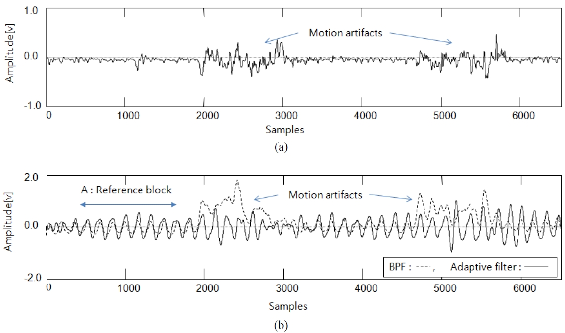
The results are shown in Figs. 5 and 6. In the experiments, we analyzed two performance parameters: signal reconstruction and heart rate variation. In analyzing the reconstruction efficiency of the signal, we used the visual test method to check whether heart pulse wave is or not. In the results, we were able to determine that the output signal of the proposed method was reconstructed despite the occurrence of motion artifacts, as shown in Fig. 5b.
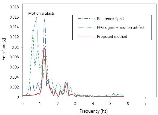
In analyzing the heart rate variation, we compared it with a reference frequency, and the result is shown in Fig. 6.
The reference spectrum is obtained from the signal of block A, which is the PPG signal without the motion artifacts. In the result, the proposed method showed that variations σ = 10.22% of the center frequency
The signal measured by using the PPG sensing device of the mobile healthcare system contains various motion artifacts occurring from the patient’s movements. The method of using an acceleration sensor to solve the problem has been suggested, but the method has the disadvantage that the sensors are very expensive. Therefore, this study proposed a novel sensor device to replace the acceleration sensor, and reported on the performances of the proposed sensor through experimental investigation. According to the experimental results, we determined that the acceleration sensor may be replaced by the proposed sensor. Therefore, it will be possible to design a low-cost device if the proposed method is applied.