Turbopump-type liquid rocket engines can be categorized into open cycle and closed cycle engines. Although both open cycle and closed cycle engines are realized in many forms depending on the propellants, if kerosene and liquid oxygen (LOx) are used, a unique cycle may be used for each open and closed cycle, such as the gas generator and the staged combustion cycle, respectively. Gas generator cycle engines have relatively low pressure inside the main combustion chamber and the gas generators. In addition, there is no direct relationship between the combustion pressure in the main chamber and in the gas generator.
Inside the gas generator, combustion occurs in a fuelrich condition. Since the exhaust gas is discarded after it drives the turbine, it can hardly be expected to generate thrust from the gas generated by the gas generator. Thus, the overall performance of the gas generator cycle engine decreases by as much as the amount of the propellants fed into the gas generator (Huzel et al. 1992, Sutton & Biblarz 2001).
On the other hand, staged combustion engines use preburners instead of gas generators. The main function of the preburners is the same as that of the gas generator, which is generating gas to drive the turbine. After driving the turbine, the gas generated by the preburner goes into the main combustor and burns again. This mechanism is the major difference from the gas generator cycle. Since the turbine driving gas is not discarded, all of the propellants can be used to generate thrust. Thus, staged combustion cycle engines have advantages over gas generator cycle engines in terms of both thrust and specific impulse. However, staged combustion cycle engines require more technologically advanced components than those of gas generator cycle engines. The preburners are run by oxygen-rich combustion at very high pressure, the turbines are driven by hot oxygen-rich gas, and the main combustors have a two-phase reaction. As these components require very qualified materials, and a sophisticated design and manufacture, the development risk is relatively high.
Preburners, one of the key components of staged combustion cycle engines, have been successfully used only by the former Soviet Union. Some attempts were made in the US to develop preburners, but these were inactive for decades for various reasons, including funding and/or development policy (Yost 1978). However, encouraged by the recent success of the RD-180, which was adapted to the Atlas launch vehicles, the US is developing a new kerosene staged combustion engine. The new engine, AJ-26, is a modified version of the NK-33, and will be used for the Taurus launch vehicles (http://www.orbital.com/TaurusII).
As the technologies related to the staged combustion cycle are classified as national strategic resources, it is very rare for them to be transferred to other countries. Thus, it is not easy to learn such technologies through international cooperation.
There are many core technologies involved in developing preburners. Of these, it is probably the flame holding and cooling process that presents the major difficulty involved in developing preburners. Since a preburner generates an oxygen-rich, high-temperature combustion gas, and the gas drives the turbine, the gas temperature has to be strictly controlled. Thus, the oxygen to fuel mass ratio (O/F ratio) must be very high in order to satisfy the temperature requirement. However, it is almost impossible to maintain combustion with an O/F ratio as high as 60. Therefore, a very careful design is required. The design must be dependent on the design policy, the technologies must be already possessed, the specifications of the engine must be developed, and so on.
In the combustion chamber, the chemical reaction is roughly divided into two processes. First, a relatively low O/F ratio is used to keep the flame, and then the rest of the oxygen is added to the combustion gas from the first reaction. This method can be realized either by injectors only, or by a combination of the injectors and the cooling channel.
In addition to the flame holding, the high O/F ratio in the preburner creates another problem. It is also impossible to cool down the combustion chamber with kerosene, because the amount of the kerosene is not sufficient to cool down the chamber. So, the only alternative is to use LOx. Needless to say, the cooling scheme is dependent on the preburner design philosophy. If triplex injectors are used for the preburner, the thermal load on the combustion chamber is relatively low because the primary combustion occurs inside the injectors. On the other hand, if simplex injectors are used, the combustion occurs inside the chamber and the chamber wall is directly exposed to high temperature with the oxygen-rich gas. For this reason, extreme care is needed to prevent the chamber wall from melting down.
The main purpose of this research is to generate the appropriate design parameters for the preburner. Many designs were made, and one of the best results was selected to fabricate the test model. Thus far, the test model has been run 6 times through hot firing tests with a reduced combustion pressure and/or mass flow rate. Because of the difficulties involved in measuring the temperature of the wall during the test, the wall temperatures were not properly measured. However, the wall seemed to suffer no damage after the tests. In addition, the chamber and the mixing head stood for the pressure and leak test. Therefore, even though the fire tests were not performed with nominal conditions, since the wall was not damaged by the heat, the numerical analysis seemed to provide a good design guide for the preburner.
The preburner currently being developed is suitable for a small liquid rocket engine. The overall configuration is shown in Fig. 1. As an initial prototype, the preburner is divided into two sections, one of which is the mixing head, and the other the cooling channel and the chamber.All the fuel and a small portion of the total LOx enters the chamber through the mixing head. The rest of the LOx goes into the chamber after running through the cooling channel. Thus, it is the LOx running in the cooling channel that is responsible for the cooling of the inner surface and the combustion gas. The propellants entering the mixing head burn in the chamber and generate hot combustion gas. The amount of LOx entering the mixing head is determined by repeated calculations to balance the heat generated and sunk by the combustion and the cooling. The combustion gas with a low O/F ratio is generated and mixed with the LOx from the cooling channel in the first combustion zone and in the second combustion zone, respectively.
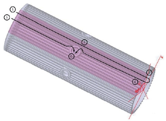
As previously stated, unlike other usual combustion chambers or gas generators, the LOx from the cooling channels does not goes into the mixing head but goes into the chamber directly. Thus the cooling channel configuration is very unique. Fig. 2 is the inner cylinder in Fig. 1 composing the cooling channel.
Basically, there are two passages of the LOx flow, one of which is short and the other of which is long. The short passage, called Route 1, is directly from the inlet to the central hole. This is the route ⑤⑥. The long passage, called Route 2, is from the inlet, all the way to the end, turning back around and then returning to the central hole. This is the route ①②③④⑥. The two routes were considered, because it was found to be impossible to satisfy the pressure loss requirements if all of the LOx runs through Route 2. Many computations were performed to determine the mass flow rates of Route 1 and 2, and the channel geometry.
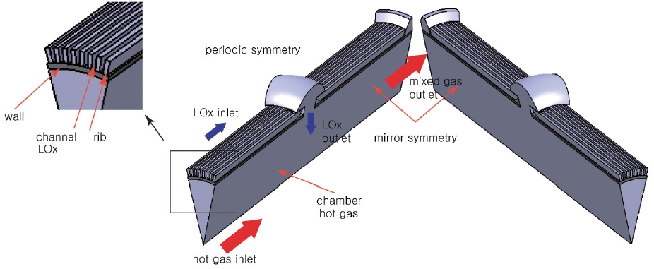
There are a total of 6 central holes on the chamber, and thus the channel configuration is periodically symmetrical by 60 degrees, and even the 60-degree symmetry section has a mirror symmetry along the center line. Therefore, only the 30-degree section can represent the whole channel. The simple schematic is shown in Fig. 3.
Fig. 3 is the model for the numerical analysis. Since the main focus of this work is to determine the design parameter of the cooling channel, the mixing head is not considered. There are two distinct inlets and one outlet in the model. One of the inlets is for the LOx and the other is for the hot gas. The LOx entering the preburner flows along the cooling channel and goes into the chamber through the central hole. The hot gas inlet replaces the mixing head.
The hot gas simulates the combustion gas that is generated by the first combustion process. This is a somewhat oversimplified model because the combustion gas temperature must not be cross-sectionally uniform. Even so, since the actual gas temperature very near the wall must be lower than the average temperature because of the injector array, the model deals with a worse-case scenario rather than actual application, and is thus expected to provide conservative design parameters.
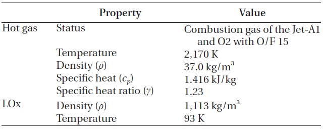
The characteristics of the hot gas were determined by Chemical Equilibrium with Applications Program (McBride& Gordon 1996). The hot gas and LOx meet at the middle of the chamber and start to mix. Naturally, the mixing process increases the temperature of the LOx, and the LOx changes to a gas-like status.
In the nominal states, the pressure and the temperature in the chamber exceed the critical conditions, and the overall mixture goes out through 'mixed gas outlet' in Fig. 3 in supercritical condition. However, this condition was not considered to make the model simple.
When the hot gas mixed with the LOx, no chemical reaction was assumed, because a large amount of the LOx would decrease the temperature and the oxygen would be added to the reaction products that already have excessive oxygen. This assumption agrees with the findings of Dorofeef (1999). Therefore, the components of the hot gas remain, even after the mixing. The whole process was assumed to have steady state, steady flow and adiabatic condition. Finally, although not shown in Fig. 3, the LOx inlet manifold in Fig. 1 is included to simulate the inlet effects. The overall inlet condition is presented in Table 1.
The heat transfer between the hot gas and the LOx is governed by the energy equations of Eqs. (1) and (3) for the fluid and the solid wall, respectively.
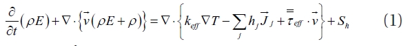


where
As boundary conditions, every wall was assumed to be adiabatic, and the exit conditions 200 bar.

Inlet condition.
3.1 Flow Analysis and Pressure Loss
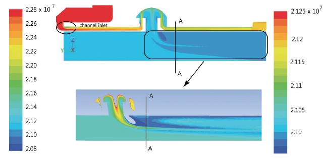
The preburner is designed to operate with around 200 bar of combustion pressure. The target pressure loss by the channel is about 20 bar. The analysis was performed by Fluent with the mass flow inlet and pressure outlet boundary conditions. The calculation was carried, matching the outlet and the inlet mass flow rate. The results of the total and static pressure distribution are shown in Figs. 4 and 5. In Fig. 4, a very interesting pressure gradient was shown along the AA line. The pressure decreases from the center (the bottom line in the figure), and then starts to increase to the middle of the cylinder in r-direction. After that, the pressure decreases again up to the wall. This kind of distinct pressure gradient in the upper picture is shown in detail in the lower picture by adjusting the pressure range.
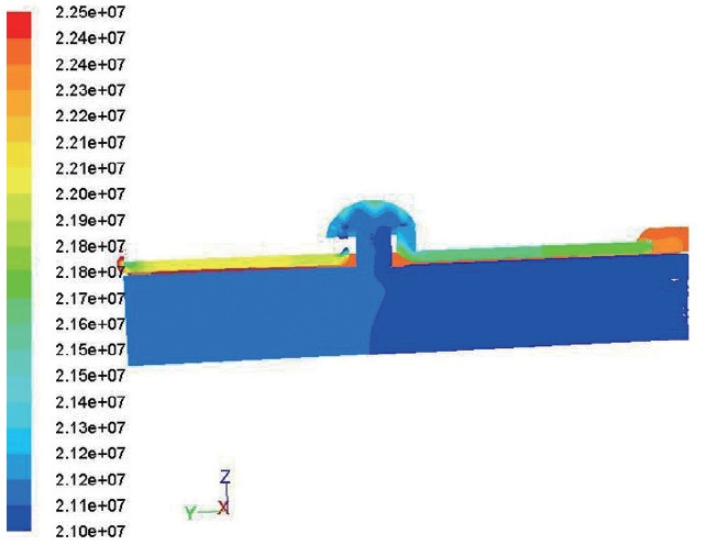
When the hot gas and the LOx collide, the momentum of the hot gas causes the direction of the LOx to change. As the hot gas mixes with the LOx, the temperature and the total pressure start to decrease. As a result, the enthalpy of the hot gas is consumed to increase the temperature of the oxygen, and the mixed gas velocity is slowed down. The total pressure distribution varies dynamically depending on the location, while the static pressure distribution shows small changes (Fig. 5).
The total pressure change from the inlet to the outlet was computed as around 20 bar, which satisfied the requirement.This calculation was confirmed by the test with a specimen designed for hydraulic test.
Many cooling channel configurations were designed to achieve less pressure loss with a large amount of heat transfer to secure the safety of the inner wall. The higher the fluid speed along the channel, the more convection heat transfer can be achieved (Holman 1989). However, a higher speed brings the trade-off of pressure loss. Thus, some criteria to balance heat transfer and pressure loss must be made.
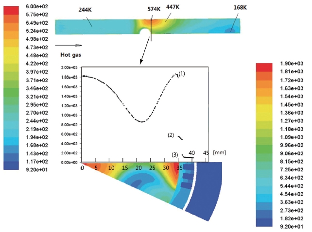
The estimated temperature distributions at the nominal conditions are shown in Fig. 6. Figs. 6a and b are the side views of channels 1 and 5, respectively. In Figs. 6a and b, the red zones are the first combustion zone, in which the gas temperatures are as high as 2,160 K. The wall surface temperature of this zone is maintained as low as 244 K, which is below 0 degrees Celsius, and the temperature is roughly uniform over the first zone. However, a very clear distinction can be noticed depending on the existence of the LOx stream coming out of the central hole
[Fig. 6.] Temperature distributions. (a) Side view of the channel 1. (b) Side view of the channel 2.

at the second combustion zone. Since the hot gas meets the LOx flux directly in Fig. 6a, the temperature decreases immediately near the wall side. However, because channel 5 is located between the center holes, the hot gas does not encounter the LOx until the LOx from the central hole diffuses sufficiently. Thus, the hot gas influences the wall further down. In addition, since only the LOx through Route 2 participates in the cooling process at the wall of the second combustion zone, the surface temperature increases until the hot gas temperature goes down due to the mixing process with the LOx. Therefore, the hottest temperature of the wall surface must be on channel 5, somewhere behind the center hole.
The surface temperatures are presented in Fig. 7. In Fig. 7, the upper plot is the temperature contour at the bottom of the surface of the inner wall. The plot below and the contour show the temperature distribution of the cross-section of the hottest spot. The left and right color bars represent the temperature of the wall surface and cross-section area, respectively. The x-axis of the graph is the radial distance from the center, and the y-axis is the temperature. The numbers (1), (2) and (3) are the thermal boundary layer of the hot gas, inner temperature distribution of the inside the wall and the thermal boundary layer of the Lox, respectively. In accordance with Fig. 4, the temperature in the cross-section area decreases to a certain point and increases up to the thermal boundary layer along the r-direction from the center.
The highest temperature on the surface was computed as 574 K, which is only 301°C. Considering that the melting point of Cu is 1,084.5°C, this temperature may be low enough to guarantee the safety of the preburner.
3.3 Visual Inspections after the Fire Tests
So far, 6 hot fire tests have been performed with lower pressure and/or lower mass flow rate than the nominal. In addition, since it was very difficult to measure the wall temperature directly, a quantitative comparison between the computation and the test results was not possible.
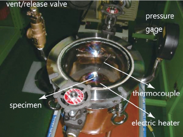
Before the hot firing tests, oxidization tests of the copper alloy that was the material of the inner wall were performed. For these tests, a vacuum chamber was prepared.The chamber was evacuated and then filled with oxygen gas up to 2.5 bar. Inside the chamber, an electric heater was installed to heat the specimen as shown in Fig. 8. This chamber is expected to simulate the combustion atmosphere of the preburner, with the exception of the pressure.
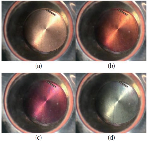
One of the test results was shown in Fig. 9. The specimen was a flat circular cylinder, with diameter and thickness of 50 mm and 1 mm, respectively. The specimen was heated up to 500°C (773 K) and exposed to the oxygen gas for 30 minutes. The surface color of (a) to (c) in Fig. 9 changed in less than 3 min. By roughly 10 minutes. after the test started, the specimen reached (d), which was assumed to be the final shape because no noticeable change was observed for the remainder of the time. The black surface color of the stage (d) is a very thin oxidized layer. Under the oxidized layer, the layer was observed to be intact. Fig. 10 is the electro-microscopic picture of the cross-sectional area.
The coalescence between the copper and the oxidized layer was not so strong that the oxidized layer was separated as shown in Fig. 10c. However, the mass change between the original and the final state is less than 3 g/m2. Therefore, with these experiments, it could be concluded that principally, the copper alloy can survive as long the temperature is maintained below the max. temperature 574 K.
Fig. 11 shows the inner wall surface of the preburner after the hot fire test. The picture on the left shows the difference between the cleaned and the uncleaned surface. The remnant on the wall is assumed to be aluminum powder from the TriEthylAluminum (TEAL), which is used as a starting fuel. The right picture shows the inner cylinder’s surface after cleaning, and no damage is found at all. Even though the pressure is lower than the nominal, because the combustion temperature is mainly determined by the O/F ratio, the temperature inside the cylinder must be not very much different from the nominal temperature. Therefore, it can be concluded that the configuration of the cooling channel was appropriate.
The computational fluid dynamics could provide the proper configuration of the cooling channels. The
highest surface temperature was measured between the center holes, because the amount of LOx running in the channels decreased, while the combustion gas was mixed with the LOx that was coming out of the center holes. The cooling channel was designed to reduce the highest temperature to as low as possible, and the actual preburner was designed and manufactured with these results.
The hot fire tests with relatively low pressure were conducted several times. As seen in Fig. 11, the surface inside the chamber appeared to be completely undamaged. If the temperatures inside the chamber could be measured, the calculations could be verified. Unfortunately, this could not be realized because no way was found to install thermocouples without interfering with the cooling channel. In fact, even if some method for installation was devised, it is believed that the thermocouples may not survive during the transition period. When the preburner ignites, the ignition fuel starts to burn first, without sufficient LOx supplied through the center holes. Therefore, even though it may be for a very short period of time, a very fast high temperature gas will be formed, and the thermocouples would have to face it directly.
Overall, even though the computed gas temperatures could not be compared to the tests results directly, the simulation can be accepted with satisfaction because the preburner was functional and the chamber wall was not damaged. It is expected that the physics of the preburner will be understood more thoroughly as the tests are progressed.


![Total pressure distribution [bar]. The left and right side bars are for the upper and lower pictures respectively.](http://oak.go.kr/repository/journal/10770/OJOOBS_2011_v28n3_233_f004.jpg)
![Static pressure distribution [bar] (side view from the mirror symmetry).](http://oak.go.kr/repository/journal/10770/OJOOBS_2011_v28n3_233_f005.jpg)