STSAT-3 is Korea’s second scientific micro-satellite.Korea Aerospace Research Institute (KARI) is the main contractor of the STSAT-3 project, in charge of the system management. Satellite Technology Research Center (Sa-TReC) is in charge of developing the satellite bus system. STSAT-3 will be launched in late 2012 by Dnepr, a Russian company.
Multi-purpose infrared imaging system (MIRIS), the main payload of the STSAT-3, consists of two IR cameras:the space observation camera (SOC) and the Earth observation camera (EOC). Korea Astronomy and Space Science Institute (KASI) is developing the MIRIS in cooperation with Korea Basic Science Institute (KBSI), i3system Inc., Green Optics Co., and other institutions. While the purpose of SOC is to survey the Galactic plane and the ecliptic poles of the celestial plane for astronomical research (Han et al. 2010), the purpose of the EOC is to observe the Earth (particularly the Korean peninsula) to monitor wild fires, volcanoes, and the vegetation index. Another purpose of the EOC is to test Korean IR technology in space. All of the subsystems of the EOC-IR detector, Dewar, readout electronics, opto-mechanical parts?are designed, manufactured, and tested in Korea, which will be a first for a space mission.
The leading countries are far more advanced in the area of space IR technology: European Space Agency (ESA) has been operating the 3 m class large IR space telescope Herschel Space Observatory (HSO) since 2009, and National Aeronautics and Space Agency (NASA) is developing a 6.5 m class James Webb Space Telescope (JWST) after the successful operation of the Spitzer space telescope (0.7 m class) and the wide-field infrared survey explorer (0.4 m class). Also, based on the Akari space telescope (0.6 m class), Japan Aerospace Exploration Agency (JAXA) is now planning SPICA, a 3 m class space IR telescope.
In Korea, KASI has developed several IR systems so far. The first Korean IR camera for ground telescopes, KASI near infrared camera system (KASINICS), was finished in 2006 and attached to the Bohyun-san telescope for NIR observations (Moon et al. 2008). Lee et al. (2006) developed the proto-model of space infrared cryogenic system (PSICS), which used the same IR detector as i3system Inc. to investigate the possibility of making a space-grade cryogenic Dewar that utilized a Korean mechanical cooler. We also took part in NASA’s sounding rocket experiment cosmic infrared background experiment (CIBER), an international project to develop IR cameras and spectrometers (Bock et al. 2006). Currently, the hyper-spectral infrared spectrometer immersion grating infrared spectrometer (IGRINS) is under development in collaboration with a veteran team of the University of Texas at Austin (Yuk et al. 2010). With these experiences, KASI was selected to develop the first space IR camera using Korean technology, which can be extended to many other application fields.
In this paper, we describe the system design and manufacturing results of the EOC. The design and analysis results of the electronics, optical and mechanical system are shown in Section 2. In Section 3, we describe the
One of the main purposes of the EOC is to test Korean IR technology in space. We have used an HgCdTe IR sensor developed by i3system Inc. The specification of the IR array is listed in Table 1.
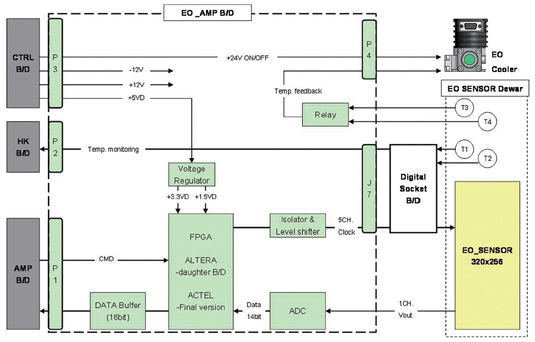
For the best performance of the IR sensor, we have used the IR sensor package from i3system Inc., including the Dewar and the cooler in the package. The EO_AMP board, which is interfacing the IR sensor, provides the
[Table 1.] General specification of the i3system infrared array.
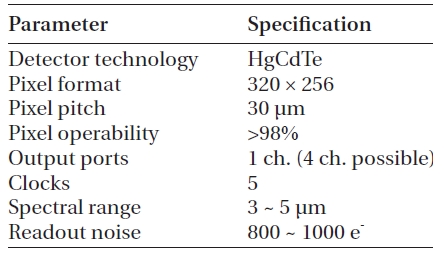
General specification of the i3system infrared array.
digital clocks and power, monitors the temperature signals from the IR sensor for cooler control, and receives the analog output of the IR sensor. The analog output signal is converted to digital data, which are transferred to the main electronics system of the MIRIS. We have used a 14-bit ADC with a dynamic range of 2.5 V. The readout speed is 5 frames/sec at maximum, but we set it to 1 frame/sec for optimal data size. The exposure time of the array can be set from 1 msec to 655.36 msec, in increments of 0.01 msec. Fig. 1 shows the block diagram of the EO_AMP board.
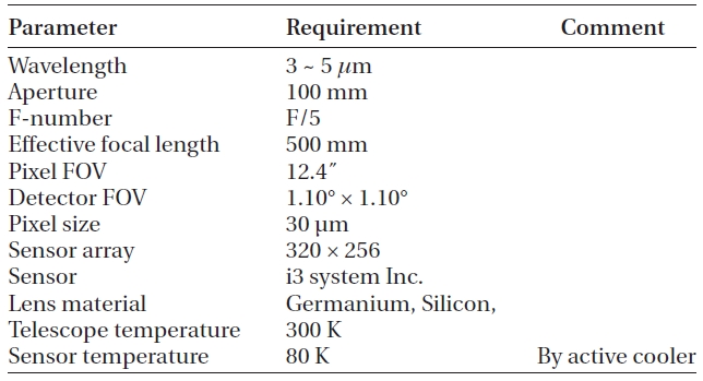
The requirements of the EOC images are as follows: the ground spatial resolution (GSR) shall be less than 50 m, and the Swath width shall be greater than 13.4 km at the nominal altitude of 700 km. To achieve these requirements, we set the F-number of the EOC optics to 5, while the aperture of the main mirror is 100 mm (Table 2).
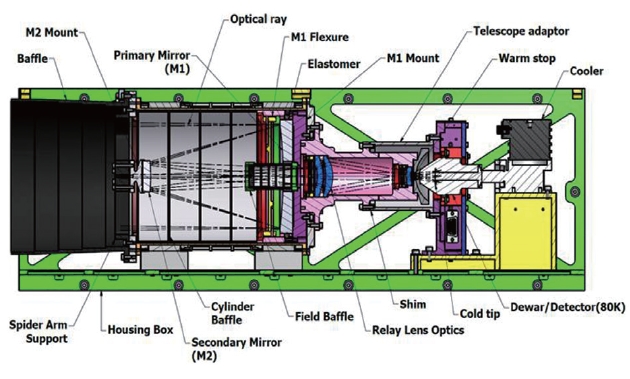
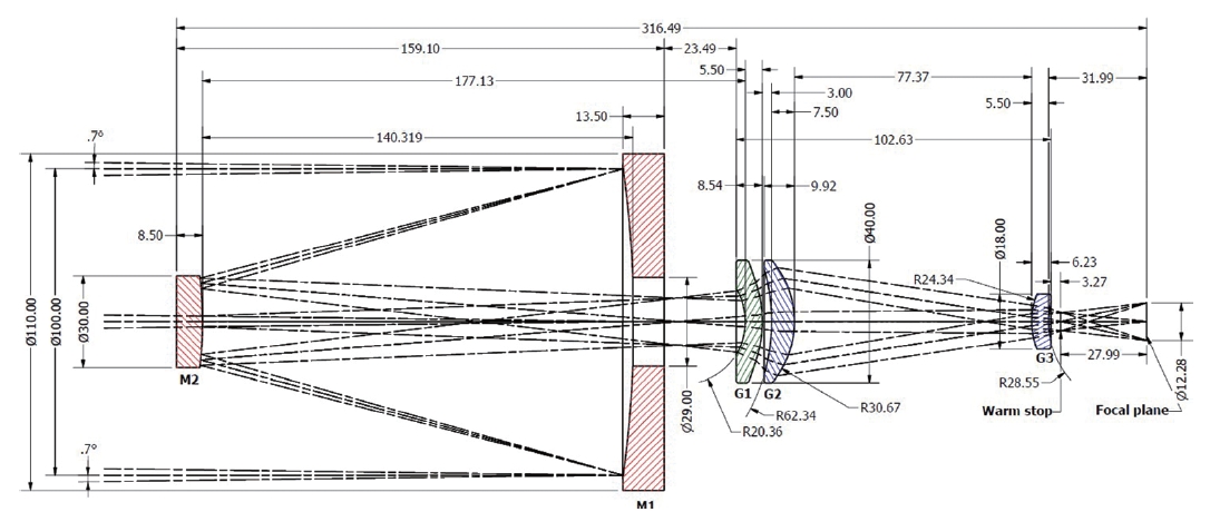
The EOC optics is composed of the Cassegrain telescope and relay lens system. The Zerodur aspherical mirrors are located in the telescope, while germanium and silicon lenses are attached behind the telescope. To eliminate thermal noise in the Dewar system, a warm stop is inserted behind the lens system. The band-pass filter of 3.8-4.8 ㎛ is covered inside the Dewar.
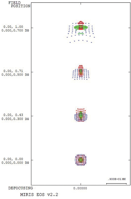
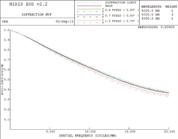
The layout of the optics is shown in Fig. 2. The expected spot-diagram and the modula transfer function (MTF) of the optics are shown in Figs. 3 and 4, respectively. The root-mean-squares (RMS) spot size is 14 ㎛, less than the pixel size of 30 ㎛. The MTF of the optics is more than 40% at the Nyquist frequency, which is bigger than the requirement of 10%.
We calculated the number of photons per pixel based
[Table 2.] Optical specification of the EOC.

Optical specification of the EOC.
on the EOC optical design. Assume that the incident energy flux from the scattered Sun light and the Earth’s blackbody radiation is around 1 W/m2/㎛/sr (Coradini et al. 2007) at dayside. When the integration time is 3
msec and the system throughput of the EOC optics is around 30%, it is 106 photons/pixel at 4 ㎛ that are illuminating the IR sensor.
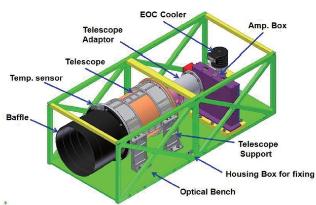
Fig. 5 shows the three-dimensional model of the EOC displaying each sub-structure, while Fig. 6 shows the internal structure of the EOC. All the opto-mechanical parts are operated at room temperature, except for the inside of Dewar, which is operated at 80 K by a mechanical cooler.
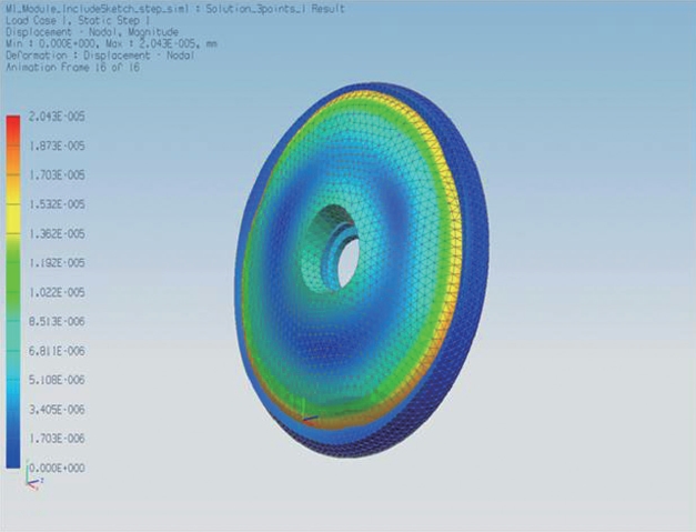
We used aluminium 6061-T6 for most mechanical parts. The structure and thermal analysis of the EOC is simple, because the opto-mechanical modules (except for the inside of Dewar) are operated at room temperature and are firmly fixed to the external frame. For this reason, only the launching stress and the normal space thermal environment should be considered in the analysis.We have analyzed the distortion of the main mirror according to the stress from the supporting structure, because the main mirror is the biggest and the most massive part in the EOC optical system. In Fig. 7, the analysis result shows that the distortion is not bigger than 20.4 nm at the stress of 10 G, which hardly changed the optical performance of the system. See the detailed analysis procedure and results in Park et al. (2011a).
3.1 Opto-Mechanical Parts
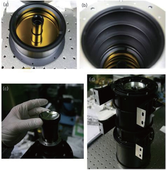
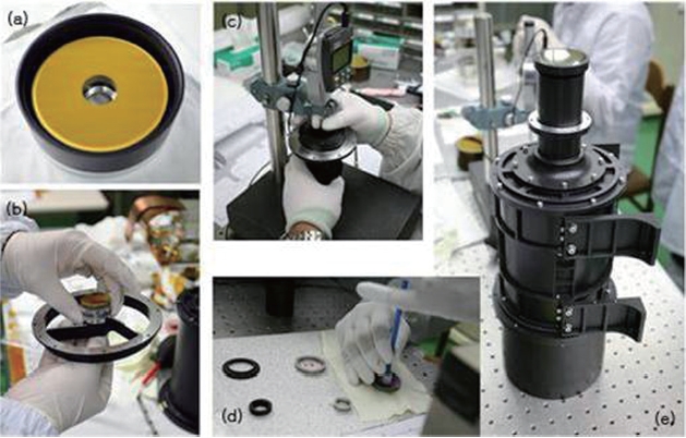
The relay lenses were manufactured and tested by Green Optics Inc. All optical and mechanical parts were measured before assembly and selected when they were within the tolerance limits. Figs. 8a-d shows the procedure of the optics parts, while Figs. 9a-d shows the mechanical assembly procedure.
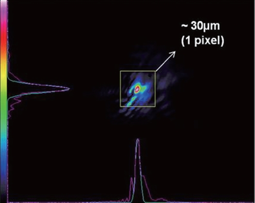
The aspherical feature of the primary mirror is most important for the performance of EOC system. Accordingly,we measured the point spread function (PSF) of the system after assembling the primary and the secondary mirrors. The analyzed RMS PSF size is 29 ㎛ at 632.8 nm. Fig. 10 shows the measured image of PSF, which is enclosed in one pixel, indicating that the mirror parts are satisfactory.
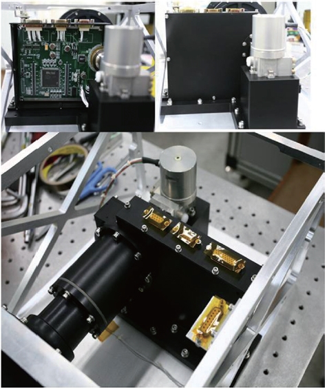
Fig. 11 shows the Amp box of the EOC. The Amp box holds the Amp PCB, which controls the IR sensor and converts the analog signal to a digital signal. The Amp box also interfaces the Dewar to the opto-mechanical parts, and the cooler to the bottom plate for heat conducting.
The flight model (FM) integration of the EOC follows the basic procedure of part inspection, parts integration, module integration, and system integration. The opto-mechanical module and the Amp box module are assem-
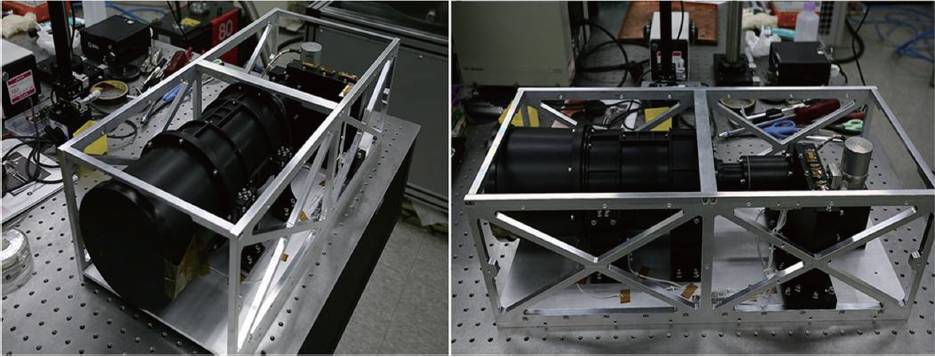
bled with a shim. The shim adjustment is performed at Korea Photonics Technology Institute (KOPTI) via optical alignment with a black-body source. The camera is then integrated to the Housing box?a rectangular structure for building into the satellite. The temperature monitoring module is also integrated with a harness on the camera. Fig. 12 is the picture of the assembled EOC.
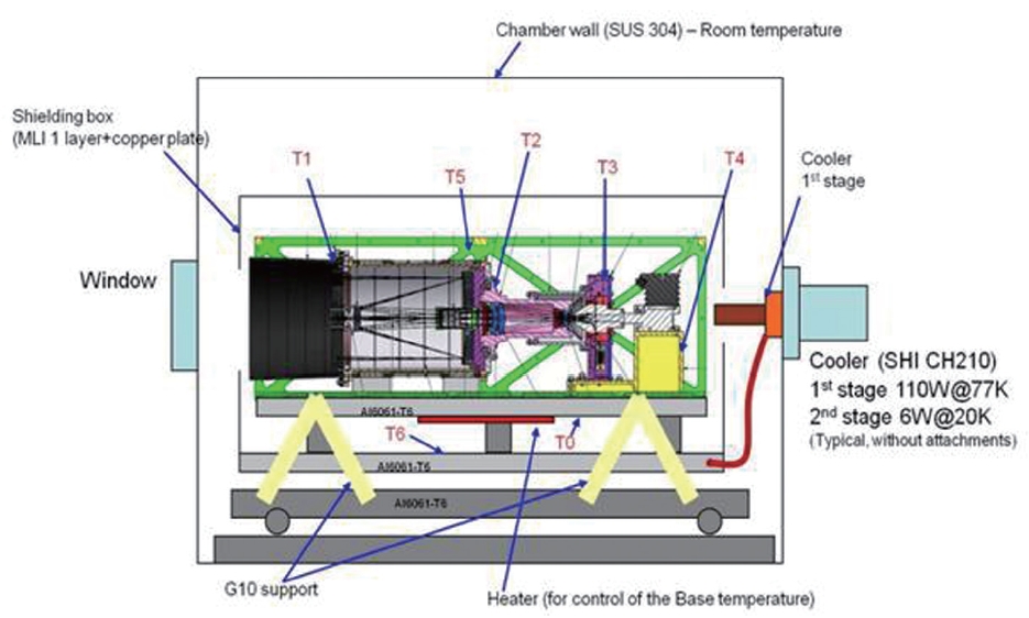
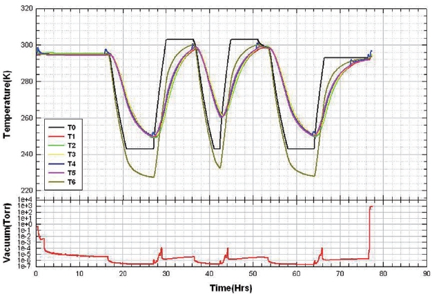
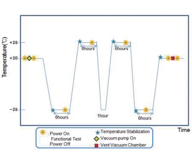
We finished the integration of the EOC in August 2010. We then performed the environment tests of the EOC. Fig. 13 shows the configuration of the EOC thermal-vacuum test. We put the EOC into the thermal-vacuum chamber, which has a two-stage mechanical cooler and a heater. To monitor the temperatures of each subsystem, we installed 7 temperature sensors, as indicated in the figure. The required temperature range is from -25oC to
25oC, as shown in Fig. 14. The resulting monitoring data are displayed in Fig. 15. T0 (black solid line) is the base-
[Table 3.] Shock response spectrum.
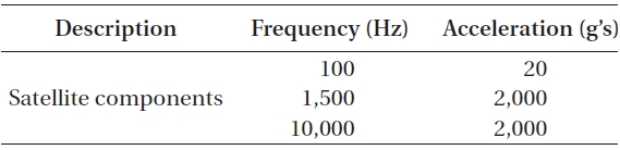
Shock response spectrum.
plate temperature that controls the whole system, as required in Fig. 14. The vacuum is maintained below 10-6 torr during the test. We have checked the images of EOC during two hot soaks and two cold soaks, confirming that everything worked well.
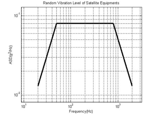
The component level vibration and shock test specifications are shown in Fig. 16 and Table 3, respectively. The EOC engineering qualification model was attached to the spacecraft structure test model for the vibration test, and passed the test. For the EOC FM, only the system level vibration test shall be performed after the EOC is integrated into the spacecraft.
We performed system calibration to convert the detected photon intensity to the actual temperature, and the field test to check the image quality. Both tests were successful: the system MTF was measured at more than 16% when the Nyquist frequency was up to 16 cycles/mm, which is sufficient to meet the requirement. Also, the obtained minimum resolvable temperature difference started from 50 mK at 0.1 cycles/mm. See the detailed test procedures and the results in Park et al. (2011b). Finally, the EOC was delivered to the spacecraft system for integration. When the STSAT-3 is integrated as a whole at the end of 2011, the flight model system environment test shall be finished soon after. The STSAT-3 will be launched in 2012, carrying the EOC.
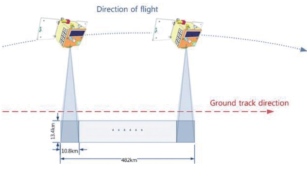
When the STSAT-3 is launched, the EOC will observe the Korean Peninsula for two orbits per day during the initial operation period of the first month. The following 13 months are allocated to the space observation camera,so only one test observation of the EOC per every 4 months shall be operated in this period. The EOC will then observe 6 orbits/day for 8 months. Note that if there is any emergent requirement, e.g. wild fires, then the EOC can be operated at any time.
The operation concept is as follows (see Fig. 17):
? Spacecraft orbit: altitude 700 km (TBD), Sun synchronous
? Swath width: ~13.4 km
? Ground spatial resolution: ~42 m
? Ground speed: ~6.7 km/sec
? Frame observing time: 3 msec (TBD)
? Observation time per orbit: 1 frame/sec × 72 sec150 (~480 km)
We have designed, manufactured, and tested the EOC of the MIRIS onboard the STSAT-3. The EOC will be the first space infrared camera made by Korean technology. Therefore, we not only can make use the various Earth images taken by the EOC, but can also use the IR technology in many fields of application.