Photonic devices used for precise management of light polarization have been gradually diversified to provide technical solutions for various applications such as coherent optical communications, polarization-sensitive coherent tomography,and optical sensors detecting polarization changes [1-3]. As a crucial device for the polarization control, integrated optical polarization converters have been investigated based on various materials such as semiconductors, silica, and polymers[4-6]. The polarization converters with a thin-film waveplate inserted in the middle of a waveguide have been utilized in arrayed-waveguide grating multiplexers to reduce their polarization dependence [7]. The thin-film waveplate was prepared by stretching a polyimide film during the in-situ monitoring of the imposed birefringence [8].
Polymer waveguides have good compatibility with thin-film waveplates made of plastic material, and fabricating various polarization controlling devices incorporating birefringent polymers has been explored [9-11]. In this work, a UV curable liquid crystal material, reactive mesogen (RM), is used to prepare thin-film waveplates, and the film is then utilized to fabricate polymer waveguide polarization converters.RM materials have been widely used to form phase retarders for liquid crystal displays [12]. It has been reported that the RM material can withstand 200℃ [13]. In comparison to thin-film waveplates made of stretched polyimide, the RM molecule is self-aligned along a predefined optic axis on an alignment layer and therefore facilitates the fabrication of thin-film waveplates. The RM film fabricated in this work exhibits excellent polarization conversion efficiency as well as a low insertion loss when it is inserted in the middle of a polymer waveguide. Wideband polarization conversion efficiency is observed for the wavelength range from 1500 to 1600 nm, and the temperature dependence is also evaluated.
II. FABRICATION OF RM WAVEPLATES AND POLYMER WAVEGUIDES
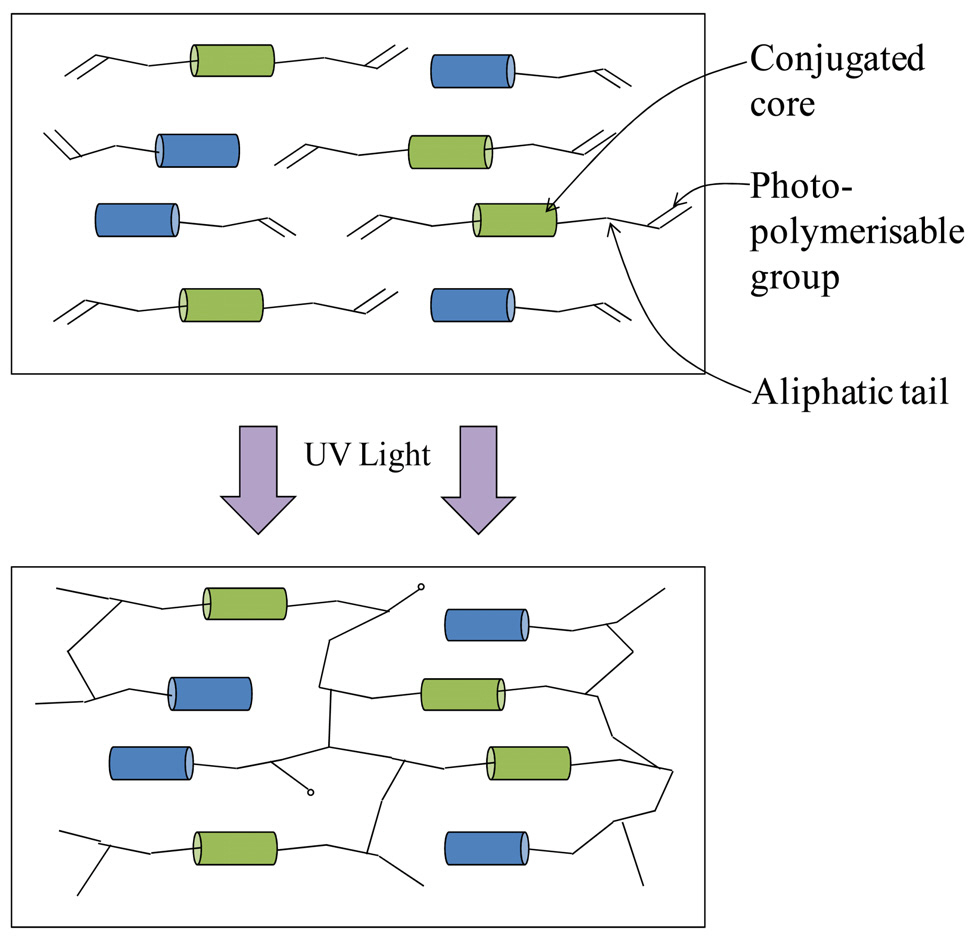
The birefringence of an optical polymer is dominated by its molecular structure, which determines the polarizability of the organic molecule. If the organic molecule consists of a path of conjugated bonds that enables charge transfer along the path, it will have higher polarizability or a higher refractive index for electromagnetic waves polarized along the path. RM has a rigid conjugated core, which is
responsible for the semiconducting behavior of the molecule,and at both ends of the core, photopolymerizable groups are attached, as shown in Fig. 1 [14]. The use of a surface alignment layer on a substrate can create large domains of aligned RMs. Then, by exposing UV light, the RM monomers are crosslinked to produce a solid plastic film. In the spin-coating and UV-curing processes, RM material does not produce the grain boundary and no crystallization occurs.The amount of birefringence is proportional to the initial birefringence of the conjugated core, and it is controllable over a wide range by using various RMs available commercially.
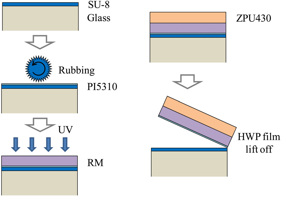
The RM material used in this work is known to have a birefringence of 0.137 for visible wavelengths. For a given birefringence, the thickness of a half-wave plate (HWP) is 5.7 ㎛ to introduce π phase shift. However, the actual birefringence and the plate thickness for 1550 nm wavelength should be found experimentally. For reducing the diffraction loss of the guided mode by the groove formed across the waveguide, thinner film is preferred. A free-standing flexible RM film was prepared by using four layers of polymer materials, as outlined in Fig. 2. SU-8 polymer was spin coated and hard baked on a glass wafer to have a thickness of 1.5 ㎛. The SU-8 exhibited weak adhesion with the polyimide material, which was spin coated on top of the SU-8 with a thickness of 100 nm for aligning the RM. The polyimide was rubbed by using a rubbing machine with a 10-cm-diameter roller covered with a velvet fiber so as to produce an anchoring force applied to the RM liquid crystal. On the rubbed polyimide, a mixed solution of RM (RMM141) and PGMEA in the ratio of 2:1 was spin coated and soft baked at 70℃ for 90 s in order to
realize molecular alignment. The RM was then cured by UV exposure with an intensity of 5 mW/cm2 for 5 min.The optic axes of the RM wave plate are determined by the alignment direction of the RM material. The direction parallel to the major axis of the elliptical RM molecule becomes the slow axis with the higher refractive index.For preparing a durable free-standing film, the thickness of film needs to be increased by coating with additional polymers. ZPU polymer from ChemOptics, Co. with a low optical loss was spin coated to increase the total thickness of the film to 13 ㎛. The ZPU polymer was cured by UV light and baked at 160℃ for 30 min. During this process,strain was built up on the film because of the volume shrinkage of ZPU. Then, it was possible to separate the film from the polyimide layer by applying a slight shear force.
To utilize the prepared wave plate film for a guidedmode polarization converter, the film was inserted in the middle of the waveguide. For fabricating polymer waveguides,ZPU-series low-loss fluorinated polymers, which were commercially available from ChemOptics, were used for preparing the core and cladding layers with a refractive index of 1.44 and 1.43, respectively. The waveguide pattern was etched on the lower cladding by using oxygen plasma, and the core polymer was then overcoated, covering the etched pattern to form an inverted rib waveguide, which resulted in an etch depth of 4 ㎛ and a core thickness of 6 ㎛.
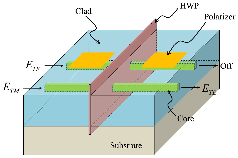
For a convenient characterization of the polarization converter,without using a polarization analyzer, waveguide polarizers were fabricated in series with the polarization converter, as shown in Fig. 3. The integrated polarizer-analyzer configuration enabled precise excitation of a TE polarization component in front of the wave plate as well as easy measurement of polarization conversion efficiency by directly measuring the output transmission power. If the HWP operates properly,a negligible amount of light passes through the device.This amount is limited by the polarization extinction ratio of the polarizers, which is normally less than -25 dB.
The polarizer absorbs the TM-polarized light by surface plasmon coupling. After coating the upper cladding with a thickness of 1.8 ㎛, Au metal was deposited to form the polarizers. Over the metal, an additional ZPU polymer was coated to increase the total thickness of upper cladding to 8 ㎛. After completing the fabrication of the waveguide structure, a vertical groove with a depth of 200 ㎛ was formed by using a dicing saw with a thickness of 25 ㎛ for inserting the wave-plate film.
III. CHARACTERIZATION OF THE POLARIZATION CONVERTER
The device was characterized by using a broadband light source. The input light was polarized by using a fiber-optic polarizer pigtailed with a PM fiber. It was directly connected to the polymer waveguide with a freedom to rotate the azimuth angle so as to adjust input polarization of the broadband light source. Before inserting the wave plate, the characteristics of the waveguide polarizer were investigated by comparing the insertion losses for the TE and TM polarizations.For the two polarizers in series with a total length of 18 mm, the polarization extinction ratio was measured to be 30 dB at a wavelength of 1550 nm. For a total device length of 30 mm, the excess loss of polarizer for the TE mode was 0.5 dB. When the HWP was inserted,polarization conversion was observed in the channel with no polarizer, and a polarization extinction ratio of 25 dB was observed. For measuring the channel with the integrated polarizer-analyzer configuration, the optical fibers had to be aligned before inserting the film because the output light was very weak. When the TE polarization was excited,an additional insertion loss of 25 dB was observed because the converted TM mode was absorbed by the analyzer.The optic axis of the HWP film was carefully aligned to
achieve the minimum output power, and the film was then fixed by using a UV-curable epoxy with low volume shrinkage.
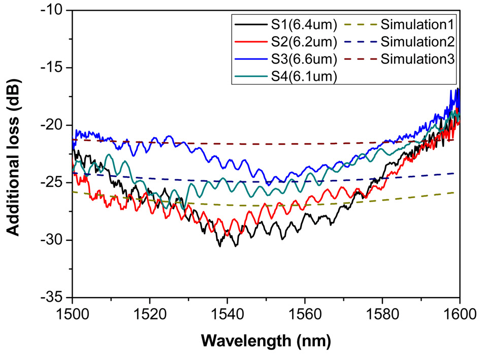
To find the optimum thickness of the HWP, samples with different thicknesses of RM film were prepared. In the integrated polarizer-analyzer configuration, the transmission loss determines the polarization conversion efficiency. Hence,the wavelength dependence of the HWP could be evaluated by measuring the wavelength dependent losses as shown in Fig. 4. The sample with a 6.4-㎛ RM film exhibited the largest additional loss that was close to 30 dB, which implied that the TE mode was almost completely converted to the TM mode, which was absorbed by the analyzer. Though the birefringence of the RM film was known to be 0.137 at 550 nm, the actual birefringence of the RM film at 1550 nm was found to be 0.121 in our experiment. For the wavelength range from 1520 to 1580 nm, the additional loss or the polarization conversion efficiency was above 25 dB.
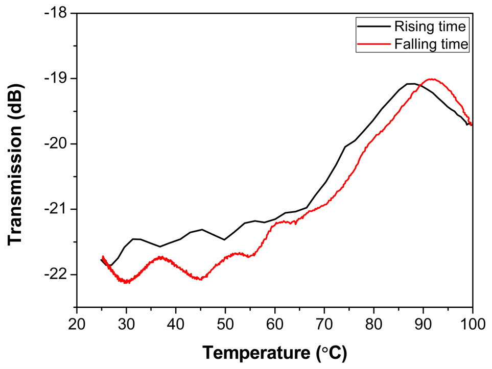
For verifying the temperature dependence of the RM-HWP,the device was operated over a wide temperature range.The polarization-converting waveguide with the polarizeranalyzer configuration was pigtailed with a PM fiber, then it was placed in a temperature-controlled oven. Initial transmission of the pigtailed device was -22 dB due to the polarization conversion and successive absorption in the analyzer.The loss decreased as the temperature increased to 90℃due to the change of the phase retardation amount. Assuming negligible change in the retarder thickness, the difference in the loss corresponded to a phase retardation of 4.7°,and the birefringence of the RM film was reduced by 2.6%. The oven had a rise time of 30 min and a fall time of 5 hours. Moreover, the actual temperature on the device surface was different than the oven temperature, which may have caused the hysteresis in the measurement.
Concerning photostability of the RM-HWP, throughout the measurement, we did not observe any degradation of the device insertion loss for the typical optical transmission power of 0 dBm.
UV curable birefringent liquid crystal molecule, RM was incorporated to fabricate a free-standing wave-plate film,and then the film was inserted across a polymer waveguide to fabricate a waveguide polarization converter. For convenient evaluation of the polarization conversion efficiency,a waveguide polarizer-analyzer was integrated in series with the polarization converting waveguide. The polarization conversion efficiency was measured to be 25 dB for the wavelength range from 1520 to 1580 nm. The waveplate film had a thickness of 14 ㎛, and it induced an additional insertion loss of 0.3 dB when the film was inserted across the polymer waveguide. In the temperature dependence measurement, the device exhibited phase retardation change of 4.7° for a temperature change from 25 to 100℃, which corresponded to a birefringence change of 2.6%. The proposed device could be used for commercial applications after a series of reliability assurance experiments.