Obtaining molecular imaging in living organisms is applicable to the diagnosis of diseases such as cancer and cardiovascular disease [1-3]. This imaging technique can also be utilized in treating these kinds of disorders by testing the clinical effects of new medication. Non linear optical (NLO) microscopy is a candidate being actively researched in this field. It can obtain the resolution of several hundreds of nanometers. So to speak, NLO microscopy is actively utilized to image the cellular details of many organs and disease processes including cell trafficking, cell migration, and molecular interactions [4-8]. The terminology of NLO microscopy actually includes all the microscopies based on multi-photon interactions such as two-photon excitation fluorescence (TPEF) microscopy, second harmonic generation (SHG) microscopy, sum frequency generation(SFG) microscopy, and coherent anti-Stokes Raman scattering(CARS) microscopy. Among these kinds of microscopies,coherent anti-Stokes Raman scattering (CARS) microscopy is preferred to other microscopies because of label-free strong vibrational signals, namely no use of fluorescent dyes [9-11]. However, in spite of this merit of CARS microscopy, multimodality based on CARS microscopy is preferable to CARS only [12-13], because different NLO microscopies each have their distinct advantages in visualizing morphological details.
When we are going to construct CARS microscopy, the microscope is absolutely required to be inserted into a living body. We know well that conventional microscope objective is so bulky that it cannot be inserted into a living body. To achieve this purpose with minimal invasiveness,we need a long slender probe-type objective, namely a probe-type microscope objective (PMO). That is, a PMO which can be inserted to internal organs through a surgical keyhole.
As a candidate for PMO, a stack of cylindrical gradientindex(GRIN) rod lenses can be easily imagined and considered. Researchers often utilize GRIN rod lenses for microscope probes [14-20]. There are mainly two cases :in vivo confocal microendoscopy connected with a fiber bundle and in vivo two-photon (or multi-photon) microendoscopy coupled with a conventional microscope objective.However, GRIN rod lenses are difficult to use in CARS microendoscopy unlike confocal or multi-photon microendoscopy,because the CARS signal is generated only at a coincidence focal point of the pump and Stokes beam with frequencies of ωp and ωS, respectively [12]. GRIN rod lenses have large amount of inherent chromatic aberration which cannot bring a focus for both frequency of ωp and ωS [21-22].
Meanwhile, there might be another choice of PMO,which is equipped with up to four lasers (488/561/633/748 nm) by Olympus Inc. for multicolor fluorescence. However,this PMO is also difficult to apply for CARS microendoscopy,because CARS microscopy chiefly uses near infrared wavelengths, namely 817 nm for pump beam and 1064 nm for Stokes beam. In addition to this reason, the PMO is not easily accessible from Olympus Inc. because of some patent problems. In order to stand at the leading edge of world class development, it is essential that an optical system development like PMO goes with molecular imaging technology. In this paper, we introduce the design procedures and techniques of PMO, especially for CARS imaging.
II. DESIGN IDEAS AND DESIGN REQUIRMENTS
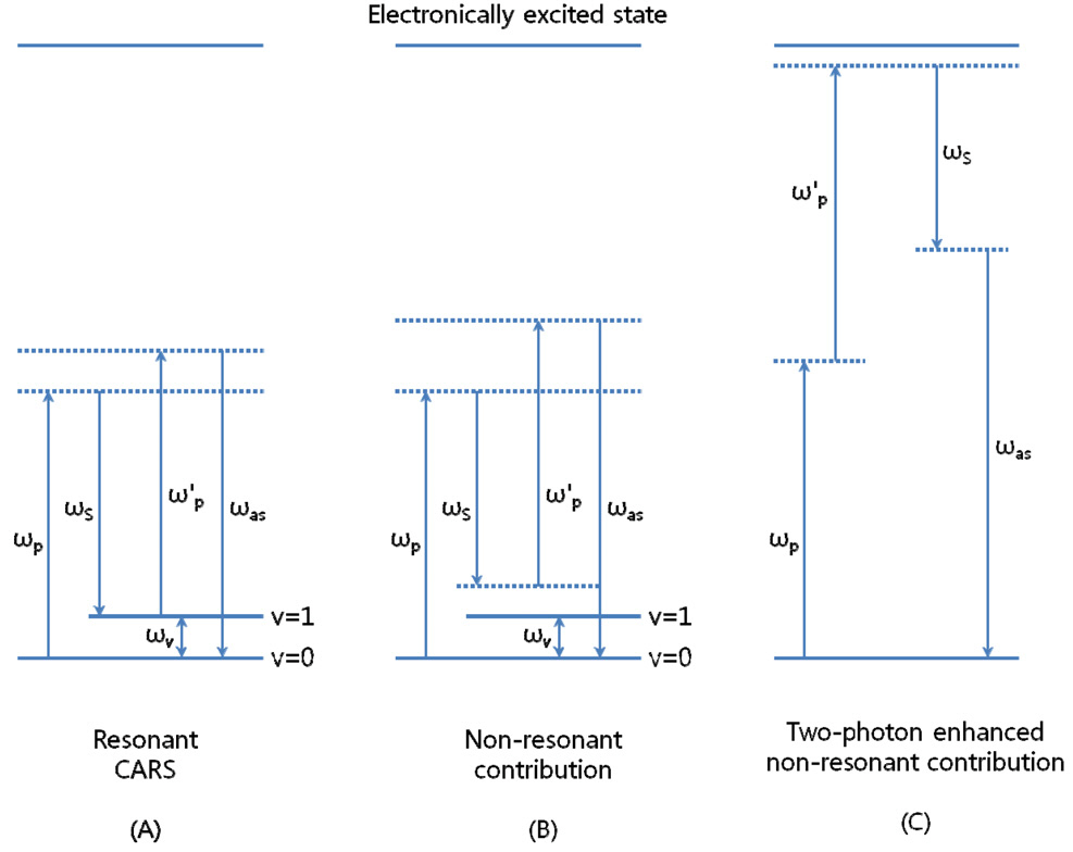
Coherent anti-Stokes Raman scattering (CARS) signal arises only at a focal point by two laser pulses with the frequencies of both ωp and ωS, called pump and Stokes beam. This means that the signal efficiency is strongly dependent on chromatic aberration between two frequencies.When the beat frequency of ωp - ωS is tuned to be resonant with a given molecule vibration (ωv), a strong anti-Stokes signal is coherently driven at ωas = 2ωp ?ωS (Fig. 1A) [23].A major improvement since the first attempt of CARS microscopy by Duncan and co-workers in 1982 [24] was the development of the use of near infrared pump (800 nm) and Stokes beam (1200 nm) by Zumbusch and co-workers [25]. This is because near infrared frequencies instead of visible ones can more effectively reduce scattering and photo damage to the in vivo sample. And it is important to realize that the sensitivity of CARS detection is limited by non-resonant contributions such as the non-resonant CARS signal (Fig. 1B) and two-photon enhanced non-resonant signal (Fig. 1C). The use of near infrared frequencies can avoid the two-photon enhanced non-resonant contribution and lead to a significant improvement in sensitivity. Therefore,the frequencies (or wavelengths) of pump and Stokes beams are determined by the research of Conor L. Evans and co-workers [12] who used 817 nm for pump beam and
1064 nm for Stokes beam for multimodality based on CARS microscopy.
As mentioned above, CARS signal is generated at a coincident focus by the third-order electronic interaction between two pulses and molecular resonant vibration. It is known that resonant CARS signal is proportional to the square of induced third-order polarization, namely P(3) as shown in Eq. (1). Therefore, the signal generation efficiency is proportional to the second order power of pump beam intensity (Ip 2) times the first order power of Stokes beam intensity (Is) [23]. This leads to the critical condition for tight focusing without chromatic aberrations, so that PMO has to be perfectly corrected on monochromatic and chromatic aberrations.
where,
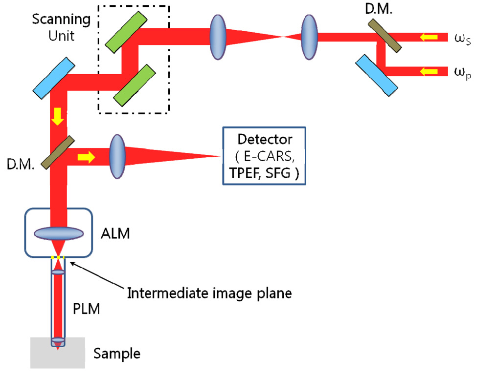
Let’s see the schematic working structure of CARS microscope.Fig. 2 shows a typical schematic diagram of an intravital laser scanning CARS microscope [26-27]. As shown in Fig. 2, PMO is composed of probe lens module (PLM)and adaptor lens module (ALM), in which PLM can be inserted to an internal organ through a surgical keyhole with minimal invasiveness. And intermediate image plane exists to mutually couple ALM to PLM. When collimated beams are incident on ALM from a scanning unit, ALM is expected to make a focal locus on an intermediate image plane. PLM is also expected to transfer this focal locus to the sample with tight focusing. If the focal points are tightly
made on the sample plane, CARS signal arises at an each point and returned back to the detector after through PLM and ALM by turns. Summarizing the role of PLM and ALM, we can say that PLM and ALM correspond to a stack of GRIN rod lenses and a conventional microscope objective in two-photon fluorescence microscopy, respectively.
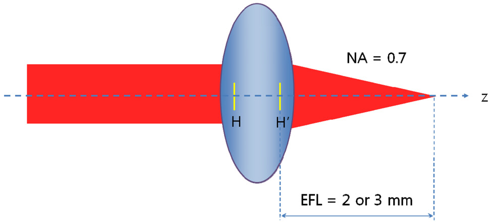
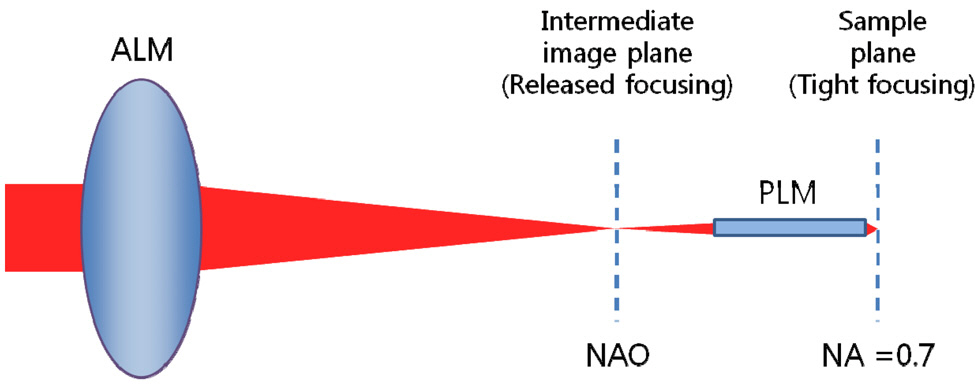
We have decided on the structure of probe-type microscope objective (PMO) which consists of PLM and ALM without a detailed explanation. If PMO is expected to consist of only one module as in Fig. 3, there is no way for PMO to be a long slender type. A miniaturized microscope objective might have an effective focal length of about 2 or 3 mm.This causes the diameter of the clear aperture to be at least 2.8 mm for a numerical aperture of 0.7 and short length of probe. In order to be a long slender type, the use of an effective focal length of 20 mm brings the diameter of the clear aperture to be 28 mm. Therefore, PMO has to consist of PLM and ALM and ALM has to make a
released focusing which causes PLM to be a miniaturized aperture, as shown in Fig. 4. The rest of the design requirements are determined by the Olympus PMO. It has the specifications such as outer diameter of 3.5 mm, field of view of 0.22 mm, numerical aperture of 0.7 at sample side, and length of PLM of 25 mm.
III. OPTICAL DESIGN OF PROBE LENS MODULE
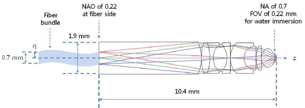
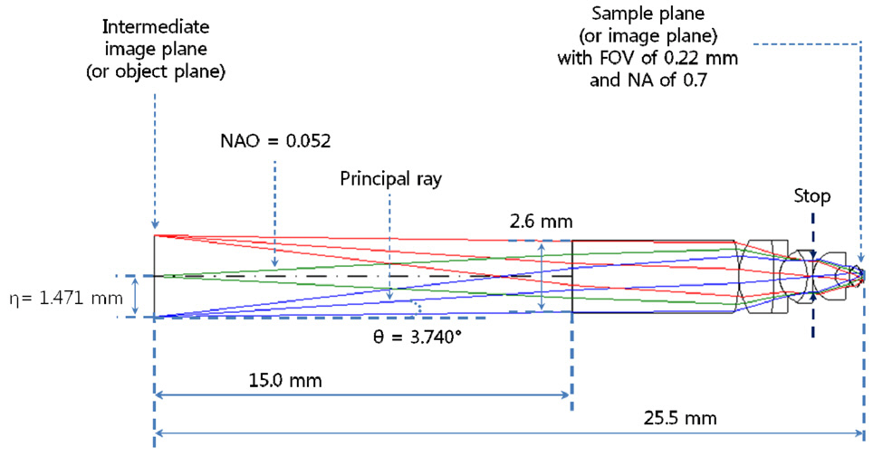
In order to design a long slender type, we must first consider two key factors: intermediate image height and numerical aperture (NA) on the sample side. Refer Fig. 5,which has already been designed by our design group for a coherent anti-Stokes Raman scattering (CARS) imaging catheter system with fiber bundle. As shown in Fig. 5,almost the whole of the clear aperture is determined by NA. This system requires a 10.4 mm total track length from the fiber bundle end to the sample plane. For a longer total track length, the object plane has to be far away from the first lens surface. This will cause the diameter of clear aperture to be larger than 1.9 mm. Considering the outer diameter of 3.5 mm with the probe length of 25 mm for Olympus PMO (probe-type microscope objective) [19,26], it can be reasonable to choose the maximum clear aperture of 3.0 mm allowing for steel barrel thickness of 0.25 mm. Then, the total track length of 10.4 mm can be lengthened up to the intermediate image height (η) of 1.5 mm corresponding to the half of the maximum clear aperture of 3.0 mm. This also leads to NAO of 0.05 by the magnification relationship of PLM. NAO of 0.05 means the released focusing for ALM in Fig. 4, which leads to high structural stability in tolerance level for the whole PMO.
Since the length of PLM has to be 25 mm, an air gap of 15 mm is inserted between the intermediate image plane and the first lens surface in Fig. 5. Fig. 5 is re-optimized to reach a goal of a long slender type without aberrations by CODE V [28]. In optimization, NAO (numerical aperture at object side) is kept to 0.05 and a merit function is composed of the square summation of Seidel 3rd order aber
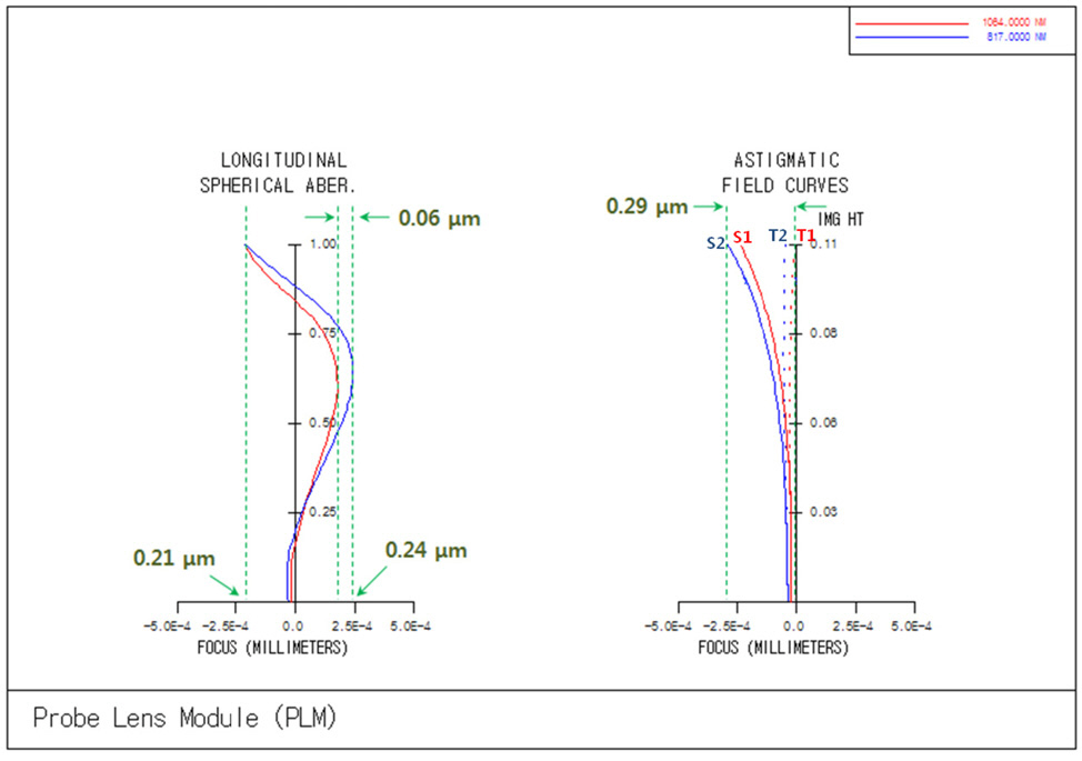
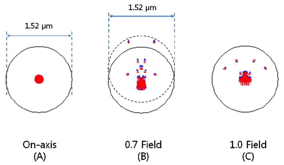
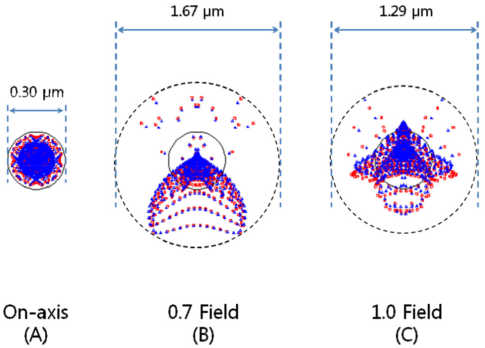
rations, 1st order chromatic aberrations, and general ray aberrations as in our previous research. Fig. 6 shows the final form of PLM with the length of 25.5 mm and the diameter of clear aperture of 2.94 mm. And the final performances of Fig. 6 are shown in Fig. 7, Fig. 8, and Fig. 9. The radius of Airy disk, namely R = 0.61 λ/NA,is given as 0.71 ㎛ for pump beam of 817 nm and 0.93 ㎛ for Stokes beam of 1064 nm. Fig. 7 shows the focus quality in terms of longitudinal spherical aberration (LSA)and astigmatic field curve (AFC). LSA represents focus errors on the sample plane arising from an on-axis point source on the object plane (or intermediate image plane).Refer to Fig. 6. And AFC also represents focus errors on the sample plane arising from an off-axis end point,namely 1.47 mm. As shown in Fig. 7, focus errors are completely corrected for both LSA and AFC. Especially, it is noted that the maximum focus deviations between pump and Stokes beam are 0.06 ㎛ for LSA and 0.29 ㎛ for AFC. Fig. 8 shows spot diagrams for on-axis, 0.7 field,and 1.0 field (off-axis end) on sample plane. As shown in Fig. 8, it is confirmed that there are almost no position deviations between pump and Stokes beam. And since the radius of 100 % of encircled energy is given to be half of 1.67 ㎛, namely 0.84 ㎛, it can be said that PLM has
nearly diffraction-limited performance without chromatic aberrations considering the criterions of the Airy disk.
IV. OPTICAL DESIGN OF ADAPTER LENS MODULE
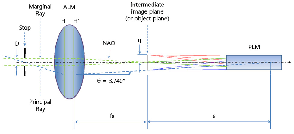
After finishing the design of the probe lens module(PLM) as a long slender type, we have to design the adaptor lens module (ALM) to link between the scanning unit and PLM. As shown in Fig. 2, the two input laser beams with frequency of ωp and ωs are synchronously scanned on ALM and then form of focal points on intermediate image plane.Refer to Fig. 4. The intermediate image plane becomes the object plane at the same time for PLM. In the design of ALM, the most difficult problem is to find how to link between the scanning unit and PLM. Let’s consider Fig. 9 which shows the geometrical relationship between ALM and PLM. From a fundamental Euclidean geometry of the triangle formed of between optical axis and principal ray[29-31], we can write Eq. (2).
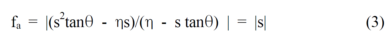
By a little algebraic calculation, Eq. (2) can be expressed as Eq. (3).
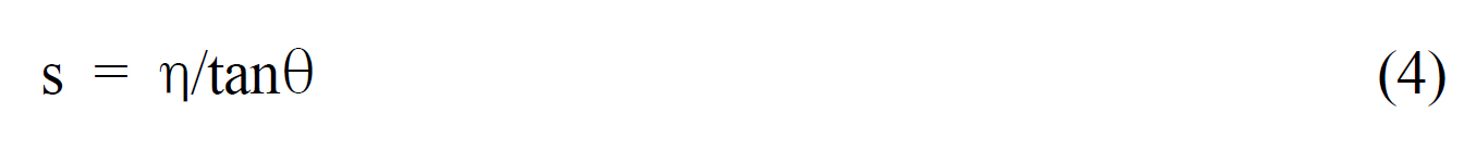
Because alternate angles are equal, s can be expressed as Eq. (4).
And the diameter of the aperture stop is given to Eq.(5) from the definition of f-number.
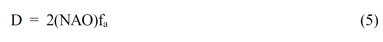
If we consider three parameters given from the designed data of PLM such as θ = 3.740°, η = 1.471 mm, and NAO = 0.052, Eq. (3) and Eq. (5) give 22.503 mm as effective focal length (fa) of ALM and Eq. (5) gives 2.356 mm to the diameter of aperture stop (D). An important thing is still left now. We have to decide the location of the aperture stop by from the principal ray. The principal ray passes through the center of the aperture stop and then is refracted by ALM keeping angle (θ) of 3.740° in the direction of the optical axis, as shown in Fig. 9. As a result, we have to keep the following 5 design parameters in the optimization process: fa of 22.503 mm, D of 2.356 mm, θ of 3.740°, η of 1.471 mm, and NAO of 0.052.
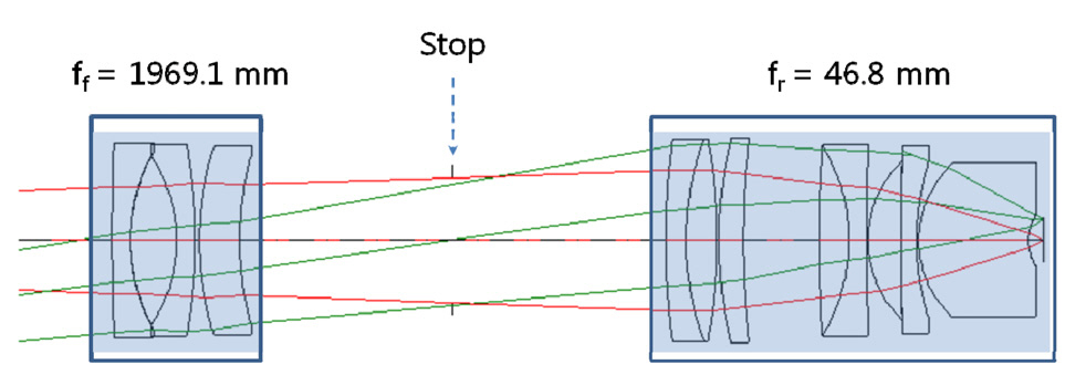
As in the design of PLM, ALM needs initial data for
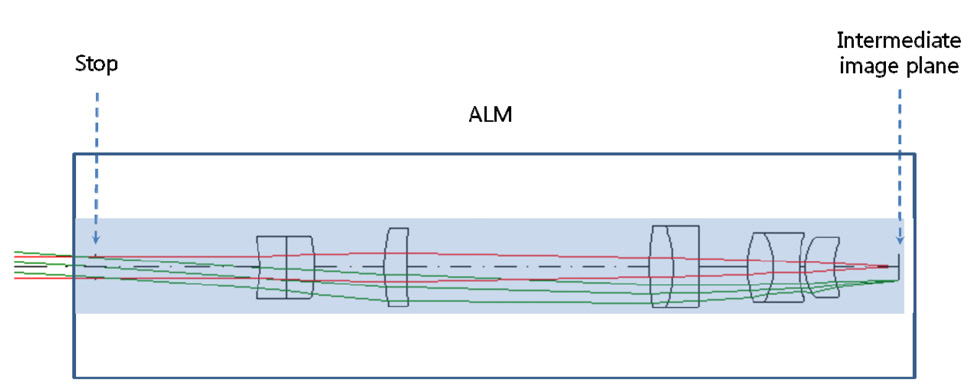
optimization. See Fig. 10 which is extracted from Japanese patents. Fig. 10 is a conventional microscope objective which consists of the front focal length (ff) of 1969.1 mm and the rear focal length (fr) of 46.8 mm. Because the front focal length can be negligible compared to the rear focal length, the front part of the optical system is excluded before optimization. As in the optimization of PLM,we minimize a merit function which is composed of the square summation of Seidel 3rd order aberrations, 1st order chromatic aberrations, and general ray aberrations. As a result of optimization, the final form of ALM and spot diagrams are presented in Fig. 11 and Fig. 12. And the radius of Airy disk, namely R = 0.61 λ/ NA, is given as 9.52 ㎛ for pump beam of 817 nm and 12.40 ㎛ for
Stokes beam of 1064 nm. Therefore, it can be also said that ALM has perfectly diffraction-limited performance without chromatic aberrations considering the criterions of the Airy disk.
We have completed designs for both PLM and ALM.It’s time to combine these modules to complete the whole system, namely probe-type microscope objective (PMO). After combining these modules, we have optimized again the whole system to eliminate some coupling disparities between PLM and ALM. As a result, we present the whole diagram of PMO in Fig. 13. For this PMO, spot diagrams are also presented in Fig. 14. Conclusively, it can be said that the final PMO has nearly diffraction-limited performance without chromatic aberrations for pump beam of 817 nm and Stokes beam of 1064 nm.
For coherent anti-Stokes Raman scattering (CARS) microendoscopy for insertion into internal organs through a surgical keyhole with minimal invasiveness, we have designed a long slender probe-type objective, namely probe-type microscope objective (PMO) instead of a stack of GRIN rod lenses.The structure of PMO had to be composed of probe-type lens module (PLM) and adaptor lens module (ALM). For the design of PLM, the core issue was to design a long slender objective, which is controlled by two key factors:intermediate image height and NA at the sample side. And for the design of ALM, the core issue was to couple between the scanning unit and PLM, which is controlled by five design parameters: fa, D, θ, η, and NAO (Fig. 6).After completing designs for both PLM and ALM, the whole system, namely PMO, was optimized again to eliminate some coupling disparities between PLM and ALM. In conclusion, the final PMO has shown nearly diffractionlimited performance without chromatic aberrations for pump beam of 817 nm and Stokes beam of 1064 nm.