Three-dimensional (3D) optical imaging using digital holography[1-4] and its applications have been investigated for 3D sensing, imaging, display, and recognition of objects[5-15]. This technique records a two-dimensional (2D)holographic fringe pattern of a 3D object using an optical in-line interferometry setup. The numerical Fresnel back propagation algorithms are applied to the holographic fringe pattern for 3D image reconstruction of the object [2, 4].Recently, a digital holographic imaging system has been explored for 3D macro- or micro-object recognition [13-18].A variety of techniques, including matched filter, neural network and statistical sampling & inference have been applied for 3D recognition of macro- or micro-objects using CPU computing [13-14, 18]. However, the high computational time of the digital holographic imaging system using recent CPUs seems to make it difficult to reconstruct or recognize the 3D objects in real-time. To overcome this problem,real-time holographic imaging by using a graphic processing unit (GPU) chip has been studied [19].
In this paper, we propose a real-time 3D object recognition system based on digital holography using GPU computing.For fast 3D sensing and imaging of objects, a holographic fringe pattern of the object is obtained by using a singlestep or two-step in-line optical interferometry setup [14].The complex image of the 3D object is numerically reconstructed from the holographic fringe pattern by Fresnel back propagation using the GPU chip. For real-time 3D recognition, the Fourier matched filter [13-14] is applied to the reconstructed complex image using the GPU computing.For the 3D object recognition without the complex image reconstruction, the matched filter can be directly applied to the holographic fringe pattern [13] using the GPU computing.We examine and compare the computational speed as a performance metric for the 3D recognition systems based on digital holography using the GPU and CPU computing for two different sensing scenarios. For the first scenario we examine the computational speed of the 3D object recognition by use of digital holography based on GPU computing with the correlation peak values calculated between the reference and unknown input complex images reconstructed with the varied holographic fringe pattern sizes.For the second case of 3D object recognition without complex image reconstruction, we examine the computational speed and performance of the 3D object recognition by
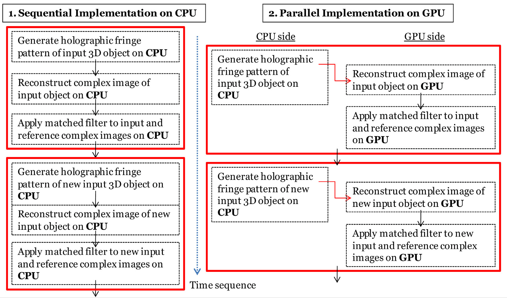
use of digital holography based on GPU computing, with the correlation peak values directly computed between the reference and unknown input holographic fringe patterns with varied holographic fringe pattern sizes. We quantitatively illustrate that the calculation speed of the proposed GPU computing-based 3D object recognition can be significantly faster than that of a CPU computing-based one. Our proposed methodology for parallel implementation on GPU for real-time 3D object recognition is described in Fig. 1.
This paper is organized as follows. In Section 2, we present the description for digital holography used in the experiments. In Section 3, we describe the matched filter for 3D object recognition. In Section 4, we illustrate the hardware and software configurations for GPU computing.Then, in Section 5, we show the experimental results and performance of GPU computing. Finally, we conclude in Section 6.
II. FAST COMPLEX IMAGE RECONSTRUCTION OF A 3D OBJECT
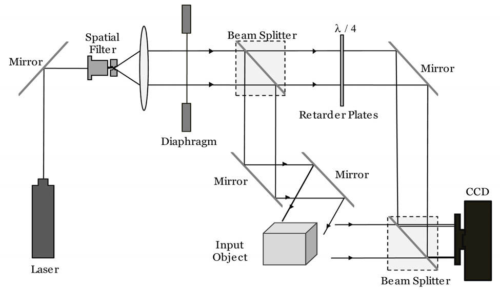
In this section, the digital holography setup for real-time 3D sensing and imaging is described. Figure 2 shows the schematic setup of phase-shifting (two-step) or single-exposure(single-step) inline digital holography [14]. For the two-step phase-shifting digital holography, the interference pattern between a Fresnel diffraction pattern under a 3D object and a parallel reference beam is recorded at a CCD camera using an inline interferometry setup as shown in Fig. 2.
Let the complex amplitude distribution of a 3D object
where
where
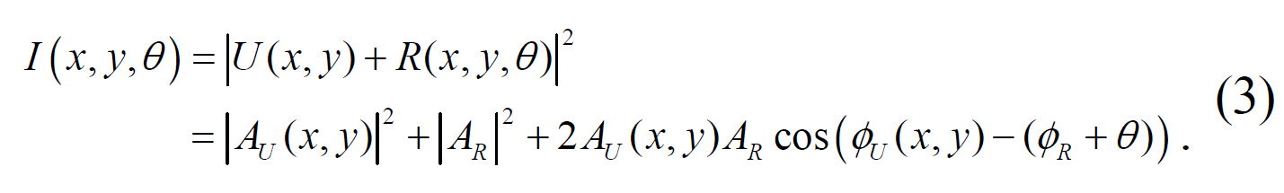
In two-step phase shifting digital holography, the holographic fringe pattern
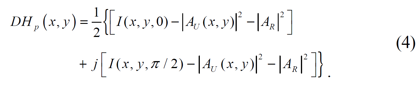
It can be assumed that the reference beam intensity ?
For a computational complex image reconstruction of the original 3D object, the following Fresnel diffraction is applied to the holographic fringe pattern of Eq. (4) [2, 13]:
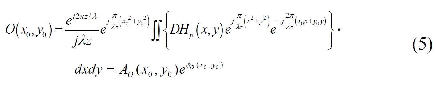
where
For fast 3D sensing and imaging of objects, a singleexposure inline digital holography (SIDH) may replace the two-step phase-shifting digital holography, which requires two different interference patterns. In the SIDH, the holographic fringe pattern
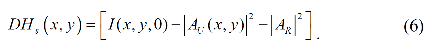
Similarly, the reference beam intensity ?
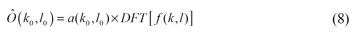
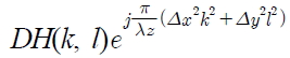
For the computational implementation of Eq. (5), the discrete Fresnel diffraction can be given as [13]:
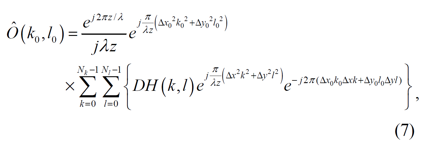
where
where
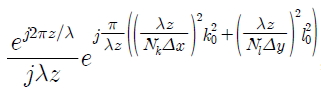
,
and
III. FAST COMPLEX IMAGE RECOGNITON
The 3D pattern recognition of unknown objects is performed by evaluation of the reference complex image
where
For the 3D object recognition without complex image reconstruction, the discrete Fourier matched filter can be directly applied to the holographic fringe pattern using the GPU computing. In this case, the discrete Fourier matched filter is [13]:
where
IV. HARDWARE AND SOFTWARE CONFIGURATIONS
The CPU chip used in our experiment is Intel Pentium D945 of 3.4 GHz and the memory size is 3 Gbyes. The GPU chip used in our experiment is Geforce GTX480 which is mounted on the GPU board. The GPU specifications are processor clock of 1.4 GHz, memory clock of 1.8 GHz,480 stream processors and a memory of 1.5 Gbytes.
All source codes are written under Matlab2010a and parallel computations on the GPU are implemented by calling Jacket Library of Accerelereyes Corporation. Jacket is a powerful plug-in connecting Matlab to the GPU which brings together the best of three important computational worlds;computational speed, visualization, and user-friendliness of M programming.
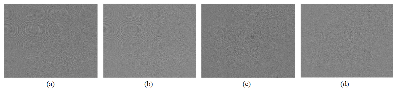
Experiments to examine the computational speed of graphic processing unit (GPU)-based digital holographic imaging system for real-time 3D object recognition are presented. In the experiments, two toy cars, car I and car II were used as a reference object and as an unknown input (false class) object, respectively. We recorded the interference patterns of each 3D car at a CCD camera with 2048 × 3072 pixels and pixel size of 12 ㎛×12 ㎛ by changing the phase of the reference beam to 0 and -π/2 using an inline phase shifting interferometry setup as shown in Fig. 2. The phase-shifting holographic fringe patterns of toy car I and car II were obtained by using Eq. (4), where we generated eight phase-shifting holographic fringe patterns with different sizes for each car, from 256×256 to 1152 × 1152 in order to see the influence of holographic fringe pattern size on the computational speed of 3D recognition with CPU or GPU computing. Each different holographic fringe pattern size was generated by extraction of the corresponding different windows in the original holographic fringe pattern with size of 2048 × 3072 pixels. Figure 3 show the real and imaginary parts of the phase-shifting holographic fringe pattern with size of 1024 × 1024 pixels for car I and car II, respectively.
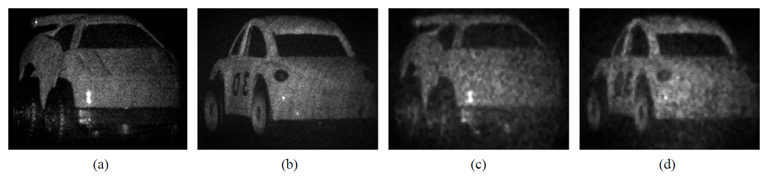
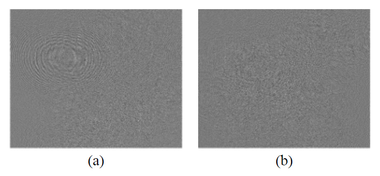
For 3D imaging, the complex images of car I and car II were numerically reconstructed from the corresponding phaseshifting holographic fringe patterns at a distance of 880mm by discrete Fresnel transform in Eq. (8) using CPU or GPU computing. Figure 4 shows the reconstructed complex images of car I and car II from the corresponding phaseshifting holographic fringe patterns, respectively.
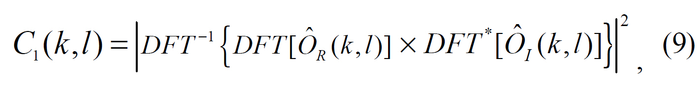
For 3D recognition, the matched filter in Eq. (9) was applied to the reconstructed complex images of car I and the car II using CPU or GPU computing, respectively. In this experiment, the complex image size was varied from
256×256 pixels to 1152×1152 pixels. The computed crosscorrelation peak values between the reference (car I) holographic image and unknown input (car II) one were 0.0014,0.0010, 0.0016, 0.0011, 0.0008, 0.0004, 0.0003 and 0.0002,corresponding to holographic image sizes from 256×256 pixels to 1152×1152 pixels. The correlation peak values are normalized to the corresponding auto-correlation value of the reference car I holographic image. In the experiments, the size of the complex image reconstructed from the holographic fringe pattern is equal to that of the holographic fringe pattern. It is noted that the computed cross-correlation peak values decrease as the complex image size increases.
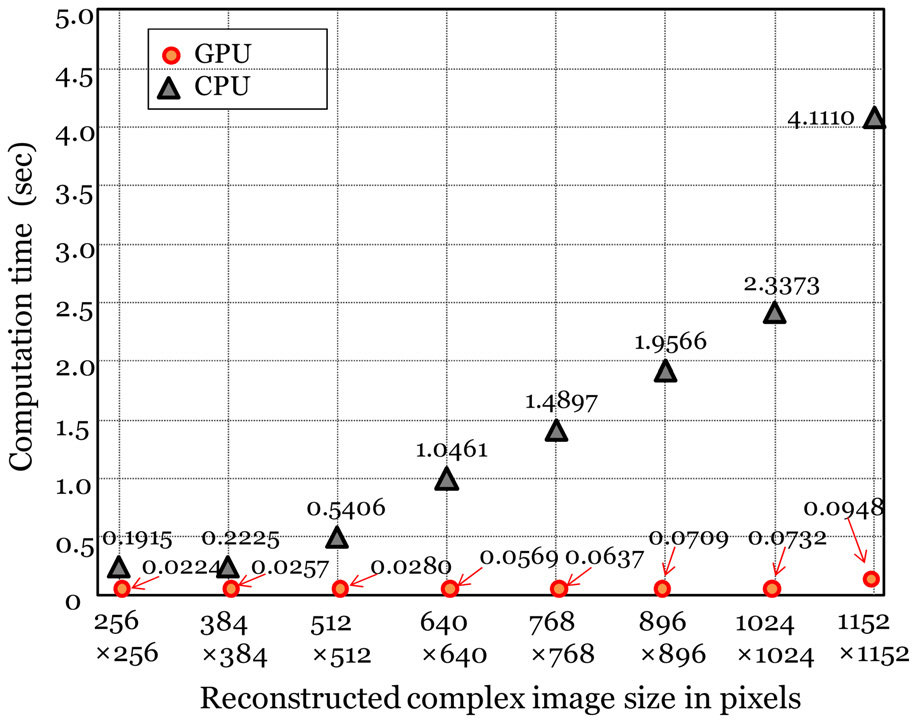
Figure 5 shows the total computation time measured by the CPU or GPU computing to differentiate the complex image of the reference (car I) from that of the unknown input (car II) by changing the size of the complex image reconstructed by using phase-shifting digital holography.The complex image size was varied from 256×256 to 1152×1152 pixels. As shown in Fig. 5, the total computation
time measured by the CPU computing to differentiate between car I and car II rapidly increased as the complex image size increased, while the equivalent by the GPU computing increased very slowly. It is noted that the size of the reconstructed complex image is the key factor to the computation time for both CPU and GPU computing.The computation time increases as the size of the complex image is increased. It is also noted that as the size of the complex image increases, the difference between the computation time between CPU and GPU computing increases rapidly. This demonstrates that parallel processing on a GPU has an enormous advantage over sequential processing on a CPU if the complex image size is large enough. As shown in Fig. 5, the increase in speed for the total computation time of 3D object recognition with the complex image size of 256×256 is approximately 8.5 while for the complex image size of 1152×1152, the increase is approximately 43.4.
Similarly, for single-exposure inline digital holography,we recorded the single interference patterns of each 3D car with a CCD camera with 2048×3072 pixels and pixel size of 12 ㎛×12 ㎛ using an inline interferometry setup as shown in Fig. 2. The single-exposure inline holographic fringe patterns of toy car I and car II were obtained by using Eq. (6), where we generated eight single-exposure inline holographic fringe patterns with different sizes ranging from 256×256 to 1152×1152 pixels for each car, in order to see their influence on the computational speed of 3D recognition for CPU or GPU computing. Figure 6 shows
the single-exposure inline holographic fringe patterns with the size of 1024×1024 pixels for car I and car II.
For 3D imaging, the complex images of the car I and the car II were numerically reconstructed from the corresponding single-exposure inline holographic fringe pattern at a distance of 880mm by discrete Fresnel transform shown in Eq. (8)using CPU or GPU computing. Figure 7 shows the reconstructed complex images of car I and car II from the corresponding single-exposure inline holographic fringe patterns.
For 3D recognition, the matched filter in Eq. (9) was applied to the reconstructed complex images of car I and car II using CPU or GPU computing, where the complex image size was varied from 256×256 to 1152×1152 pixels.The computed cross-correlation peak values between the reference (car I) complex image and unknown input (car II)were less than 0.00005 in the range of the complex image size (256×256, 1152×1152). The correlation peak values are normalized to the corresponding auto-correlation value of the reference car I complex image.
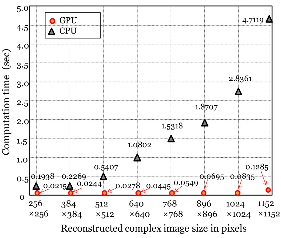
Figure 8 shows the total computation time measured by the CPU or the GPU computing to differentiate the reconstructed complex image of the reference (car I) from that of the unknown input (car II) by changing the size of the single-exposure inline holographic image. The reconstructed complex image size was varied from 256×256 to 1152×1152 pixels. As shown in Fig. 8, the total computation time measured by the CPU computing to differentiate between car I and car II increases rapidly as the complex image size is increased,while the equivalent time by GPU computing increases slowly.It is noted that the size of the complex image reconstructed by using single-exposure inline digital holography is the key factor to the computation time for both CPU and GPU computing. The computation time increases as the size of the complex image is increased. It is also noted that as the size of the complex image increases, the difference of the computation times between CPU and GPU computing increases rapidly. It demonstrates that parallel processing on the GPU is much better than sequential processing on the CPU if the complex image size is large. As shown in Fig. 8, the speed advantage for the total computation time of 3D object recognition with the complex image size of 256×256 is approximately 9.0 while for the complex image size of
1152×1152, the speed advantage is approximately 36.7. It is interesting to note that for both phase-shifting and singleexposure inline holographic fringe patterns, the computational time spent in differentiating the reconstructed complex image of the reference from that of the unknown input can be implemented in 21.5 ms~128.5 ms, which makes the 3D object recognition rate reach 7~46 frames/s. Therefore, it can be possible to obtain high object recognition rate faster than the normal real-time level (25 frames/s) by appropriately choosing the complex image size.
For the case of the 3D recognition of the object located at the same distance from the CCD camera, the matched filter in Eq. (10) can be directly applied to the phase-shifting or single-exposure inline holographic fringe patterns of two toy cars (car I and II) without complex image reconstruction.The computed cross-correlation peak values between the car I with phase-shifting holographic fringe pattern and car II were less than 0.00007 with the holographic fringe pattern size varying in the range of (256×256, 1152×1152)
pixels. The computed cross-correlation peak values between the car I and car II with single-exposure inline holographic fringe patterns were less than 0.00005 in the range of(256×256, 1152×1152). For comparison, the computed crosscorrelation peak values are normalized to the corresponding auto-correlation value of car I with phase-shifting holographic fringe pattern or single-exposure inline pattern.
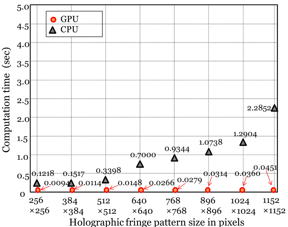
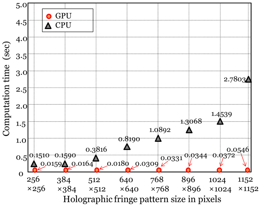
Figure 9 show the total computation time measured by the CPU or the GPU computing to differentiate the phaseshifting holographic fringe pattern of the reference (car I)from that of the unknown input (car II) by changing the size of the phase-shifting holographic fringe pattern. As shown in Fig. 9, the total computation time measured by the CPU computing to differentiate between the car I and the car II rapidly increases as the holographic fringe pattern size is increased, while that by the GPU computing is increased slowly. It is noted that the size of the phaseshifting holographic fringe pattern is the key factor for time consumption for both CPU and GPU computing, which increases as the size of the holographic fringe pattern increases. It is also noted that as the size of the holographic fringe pattern increases, the difference between the computation time between CPU and GPU computing increases rapidly.This demonstrates that parallel processing on the GPU can increase the processing speed over sequential processing on the CPU if the phase-shifting holographic fringe pattern size is large.
Figure 10 show the total computation time measured by the CPU or GPU computing to differentiate between the reference (car I) from that of the unknown input (car II)by changing the size of the single-exposure line holographic fringe pattern. As shown in Fig. 10, the total computation
time measured by the CPU computing to differentiate between the car I and the car II rapidly increases as the holographic fringe pattern size is increased, while that by the GPU computing increases slowly. It is noted that the size of the single-exposure inline holographic fringe pattern is the key factor to the computation time for both CPU and GPU computing which increase as the size of the holographic fringe pattern increases. It is also noted that as the size of the holographic fringe pattern increases, the difference between the computation time between CPU and GPU computing increases rapidly. It demonstrates that parallel processing on the GPU has an enormous speed advantage over sequential processing on the CPU if the single-exposure inline holographic fringe patterns size is large.
These experimental results in Fig. 5, 8, 9 and 10 demonstrate that the proposed phase-shifting or single-exposure inline digital holography using GPU computing can provide significantly improved computational speed for real-time 3D object recognition as compared to CPU computation.
We have investigated a real-time 3D object recognition system based on digital holography using a GPU chip. It has been illustrated that the computational speed of this 3D recognition system can be significantly faster than that of conventional CPU computing. Also, we have examined and compared the computation time of the 3D object recognition by use of digital holography with CPU and GPU computing by varying the size of the reconstructed complex image or the holographic fringe pattern of the 3D object. It has been shown as the size of the recorded holographic fringe pattern increases, the computation time of the 3D object recognition system with CPU computing increases rapidly, while that of the GPU computing increases slowly. These experimental results demonstrate that a 3D recognition system by parallel processing on a GPU has an enormous speed advantage over sequential processing on a CPU particularly for large holographic fringe pattern size. We have demonstrated that a digital holographic recognition system with GPU computing can provide significantly improved computational speed for real-time 3D object recognition as compared with CPU computing.