In long-period fiber gratings (LPFG), a fundamental core mode and the multiple cladding modes are coupled,which all propagate in the same (forward) direction. Due to unique features of low insertion loss, low back-reflection and excellent polarization insensitivity, LPFGs have attracted great interest in the optical communications and sensor applications [1, 2]. Some researchers have studied the manufacture of the core mode blocker [3, 4], band pass filter using the core mode blocker [5-7], and tunable bandpass filter using coil heater [8, 9].
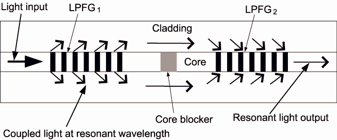
The core mode blocker is a device to block off the propagated light in the core, and pass the propagated light in the cladding. Some researchers have developed bandpass filters using LPFGs, and some of them have studied the topics based on a core mode blocker as shown in Fig. 1. In Fig. 1, the LPFG1 is used to interact between core and cladding at resonant wavelength, and light existing in the core is extinguished by the core mode blocker. The light in the resonant wavelength is propagated through the cladding to the second LPFG. The resonant light existing in the cladding by the LPFG2 is transferred back into the core.The central points of the research are to study the physical phenomenon [3, 4] and the manufacture of the bandpass filter [5-7, 9]. However the design of the flat-top bandpass filter [11] with specific customized wavelength band using an accurate analysis model was not proposed yet.
In the paper, we present the matrix model to analyze the
matrix model to analyze the LPFG structures with the core mode blocker. The proposed matrix model is a useful mathematical tool to describe the properties of the structure. We analyze the physical properties of the LPFG structure with a core mode blocker by using the proposed model. By using specially coupled feature of only the same modes in overlapped wavelength region, we demonstrate the design of the flat-top bandpass filter with the customized bandwidth.
II. THE PROPOSED MATHEMATICAL MATRIX MODEL
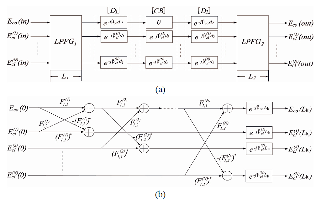
The structure in Fig. 1 is modeled as the FIR (Finite Impulse Response) filter block diagram as shown in Fig.2(a). Figure 2(b) is the signal flow graph to analyze both LPFG1and LPFG2, which is called the multiport lattice filter model [10-12]. Here,
In Fig. 2(a), the E-fields coming into and out from the structure can be written to be
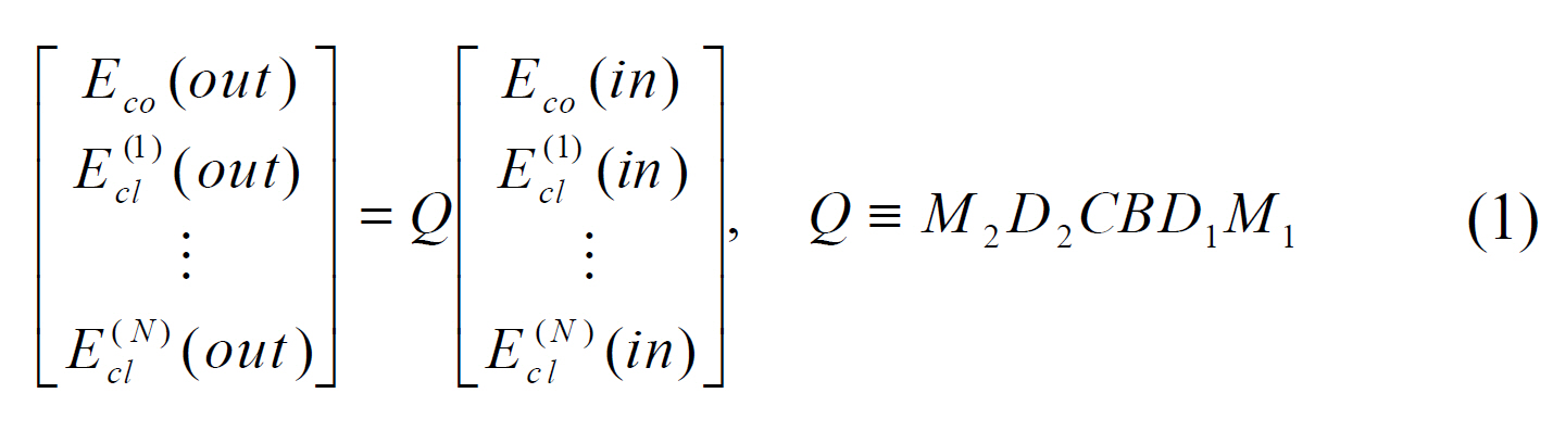
where

are diagonal matrices and
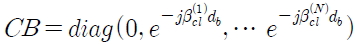
is a diagonal matrix with zero determinant.
By assuming the LPFGk, (

where
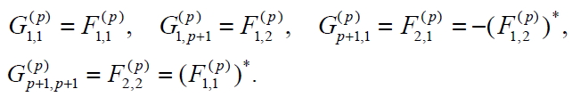
(Here, Bk,l denotes the (
and
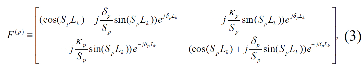
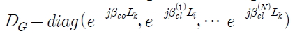
and
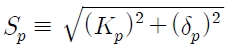
, Lk is the length of the LPFGk, δ
Note that
2×2 subsections may be interchanged freely. If LPFG1 and LPFG2 are extended as piecewise uniform LPFGs, we can also easily get the Mk using the multiport lattice filter model [10]. Now, the overall transmission coefficient
As shown in Fig. 2(a), after the coupled light on the LPFG1 is absorbed at CB, and then in the LPFG2, the propagated light in the cladding is coupled with the same modes from cladding to core, due to the orthogonality of modes as shown in Fig. 2(b) [10]. Because the overall transmission is calculated as the complex multiplying of two bandpass filters, we cannot get the spectrum in the core if two filters have entirely different bandpass regions.
We analytically calculated the transmission spectrum curves for the concatenated LPFGs with a core mode blocker in the following examples by computing the transmission coefficient
3.1. Example 1 for Uniform LPFG with Both Core Mode Blocker and Delay
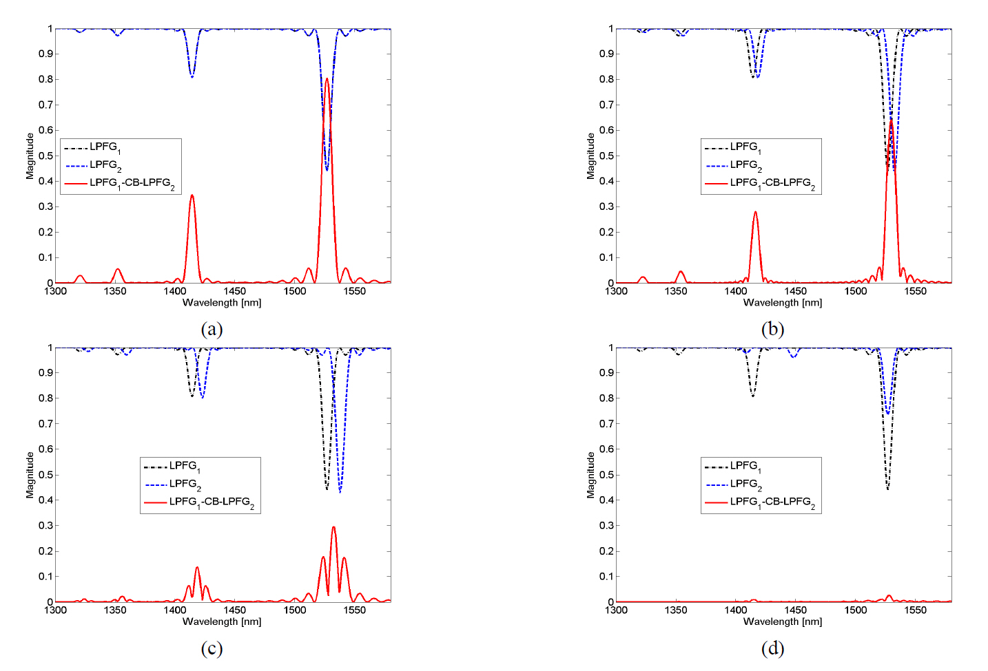
Figure 3 shows the transmission for the modes
To analyze the properties of the concatenated LPFGs with the core mode blocker, we have calculated the transmission spectra along the change of the Λ2 as shown in Fig 3. Figures 3(a)-3(c) show the transmission along the overlapped region of the spectrum band of the same modes. We can only get the bandpass spectra by coupling the same modes in the overlapped region. Figure 3(d) shows the transmission for the coupling with the different modes (
3.2. Example 2 for Flat-top Bandpass Filters
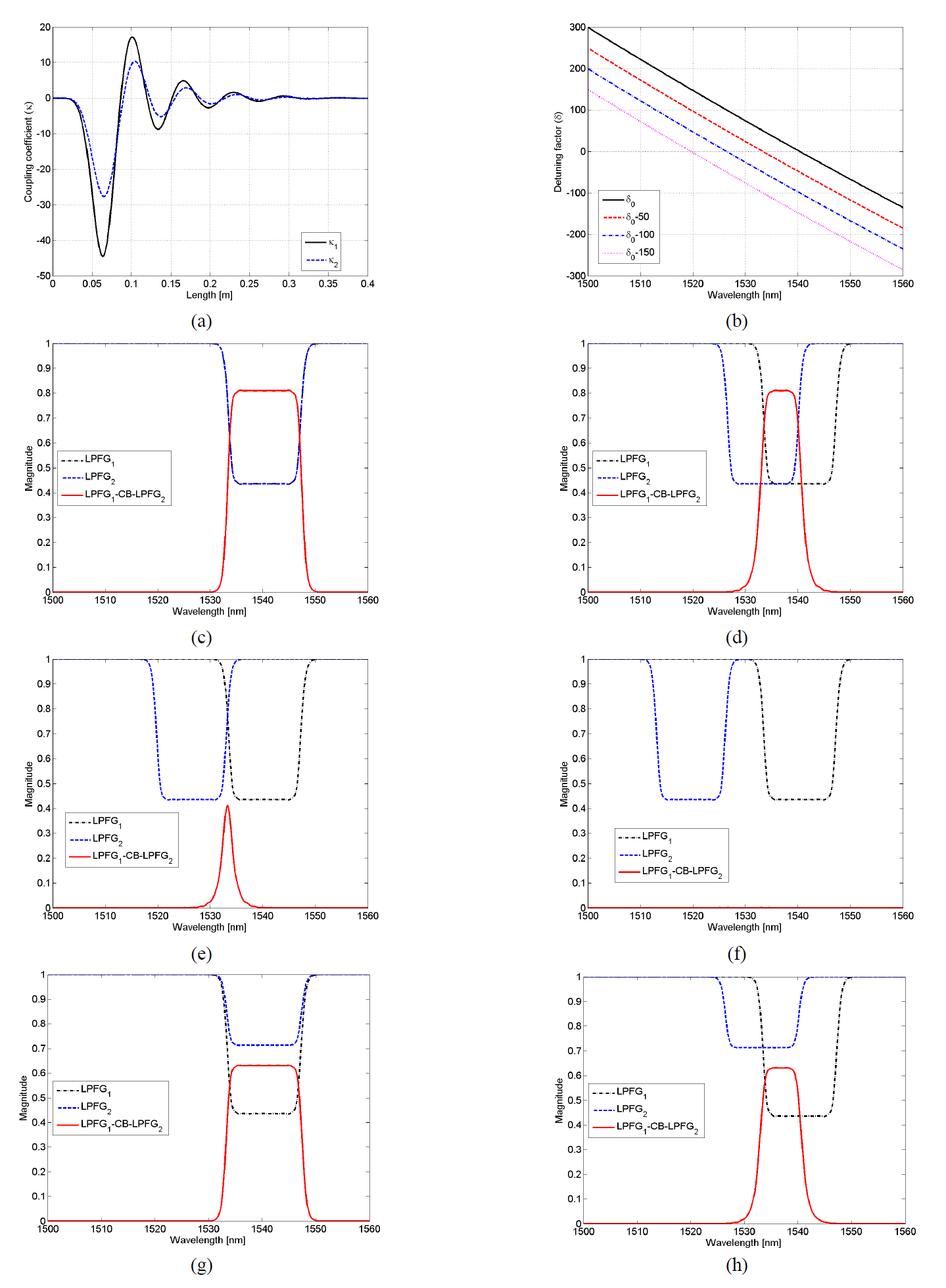
We can design a flat-top bandpass filter with the customized bandwidth using the property of coupling with the same modes and the overlapped band. We have synthesized
the tunable flat-top filter by considering a single cladding mode as shown in Fig. 4. We have utilized the coupling coefficients
The
From the results, we can observe that the bandwidth of the bandpass is changed along the overlapped band region of the flat-top band-rejection of both LPFG1 and LPFG2. If we can make the ideal band-rejection filter, we can synthesize a sharp bandpass filter with the customized bandwidth as well as the bandpass filters with a tunable bandwidth. Especially,if the bandwidth of LPFG1 and LPFG2 aren’t overlapped as shown in Fig. 4(f), we cannot synthesize the desired filter.
We also demonstrated the transmission along the overlapped region, when the coupling coefficients are different as shown in Figs. 4(g) and 4(h). The coupling coefficients
From the Fig. 4(g) and 4(h), we have obtained similar results to Figs. 4(c) and 4(d) although the LPFG1 and LPFG2 have different magnitude levels. The 3 dB bandwidth of the LPFG2 is 14.1
The analytical model for the LPFG with the core mode blocker is proposed. We have also analyzed and described the physical phenomenon of the structure by using the proposed model. We have proposed a design method of the flat-top bandpass filter with customized bandwidth. We have also demonstrated, through computer simulations, the bandwidth of the flat-top filters controlled by tuning the overlapped band region.