Pattern recognition is widely used for various applications in the fields of medicine, industry, meteorology, and more[1-3]. Shape analysis methods play an important role in pattern recognition, matching, registration, and analysis [4].Shape analysis can be classified into two methods: boundary based or internal (i.e., region) based approaches. The boundary based methods generally use the scale-space filters [5, 6] or Fourier transforms [7, 8] of the boundary, while the internal based methods use the moment [5, 9] and projection [10-12] of the object regions.
The methods which use the Fourier transforms and moments are used to classify the type of object, while the methods which use the scale-space filters and projections are used to find the dominant points and boundary locations. The shapes which can be located by the projections are flat or rectangular boundaries because those functions are generally based on the Cartesian coordinates. However, the projection functions based on polar coordinates may be used for other applications. The ring projection function, which is defined as the accumulated values of the image along a specific radius, can be used as a rotation-invariant feature [11]. The radial projection function, which is defined as the accumulated values of the image at a specific angle, can be used as a feature for topographical shapes [12].
In this paper, we propose a novel method which can separately detect convex and concave corners by using radial projection. This method is scale invariant.
II. RADIAL PROJECTION FOR CORNER DETECTION
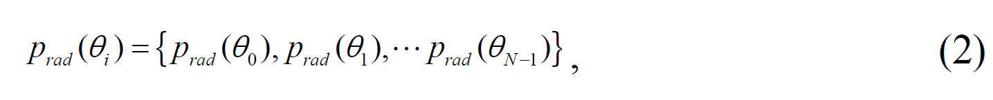
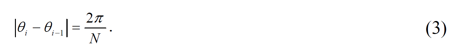
The radial projection function based on polar coordinates is defined, as follows:

where
where
To detect the corners from the computed
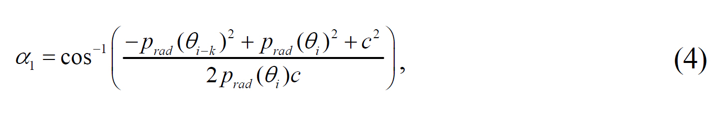
where
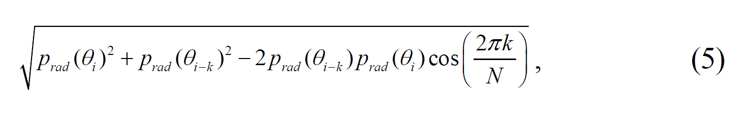
and where
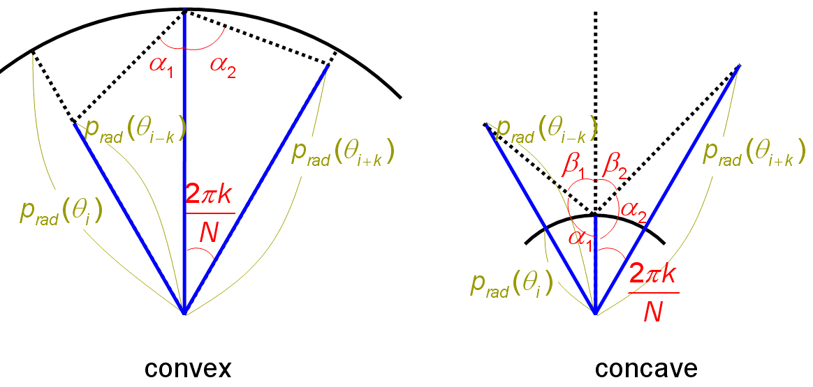
As shown in Fig. 1, if the corner angle (
III. RADIAL PROJECTION OF COMPLEX SHAPES
It is impossible to analyze a complex shape with only one origin. Thus, we separate the shape into partial regions using tight-fitting oriented bounding box trees (OBB Trees) [13].The partial shapes then become slab-sided shapes bounded by rectangles, and the corners of each shape are detected using the elliptic mod el.
Ellipses each have a major axis and a minor axis. The direction of the major axis of the approximated is calculated as the average angle from the centroid by
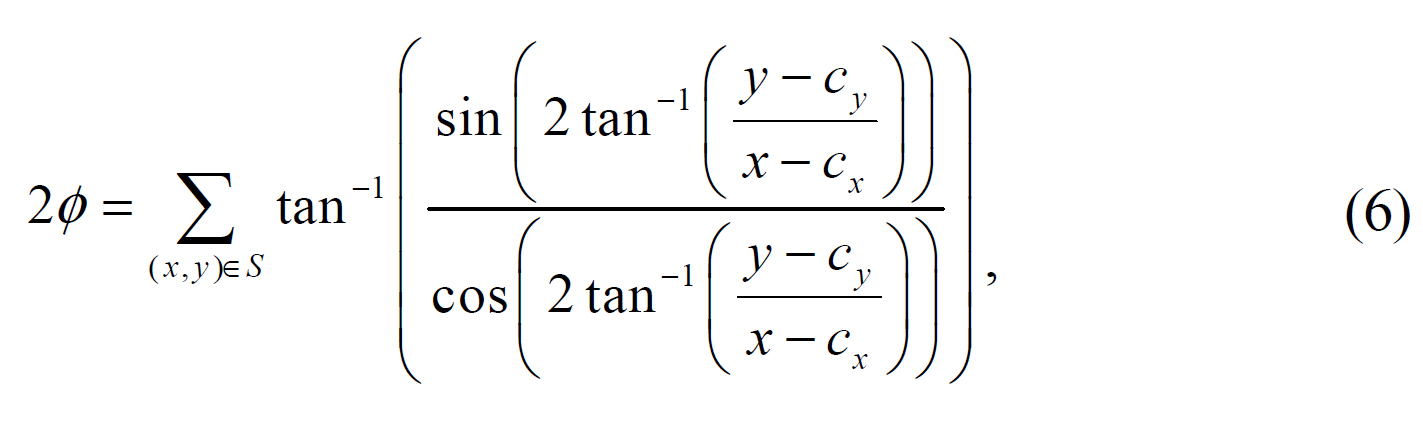
where (
slab-sided shape, and -
After detecting

where
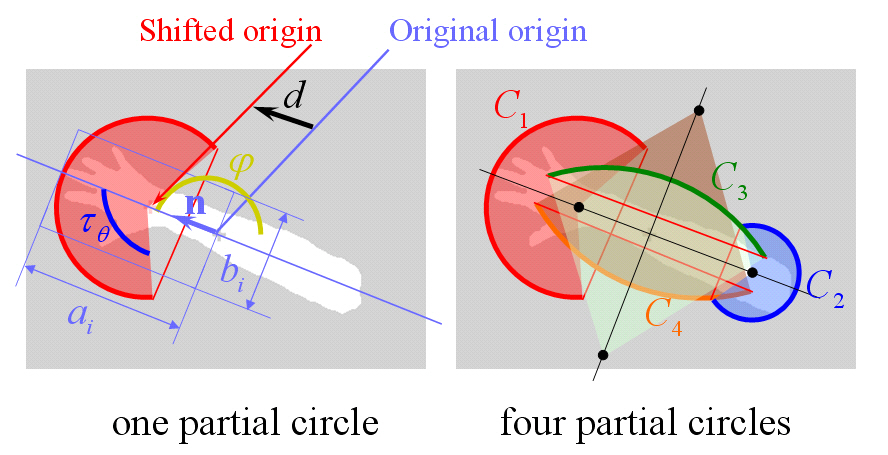
The origin may be shifted in the directions parallel to and perpendicular to n, so that four partial circles are generated,as shown in Fig. 2.
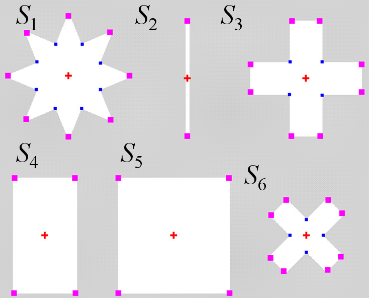
To evaluate the proposed method, we tested it using six images, as shown in Fig. 3. The test was performed for
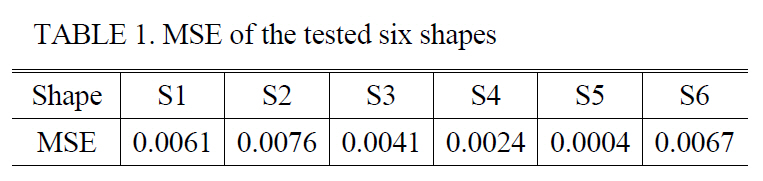
For the six shapes tested, we calculate the MSE (mean square error), which is defined by
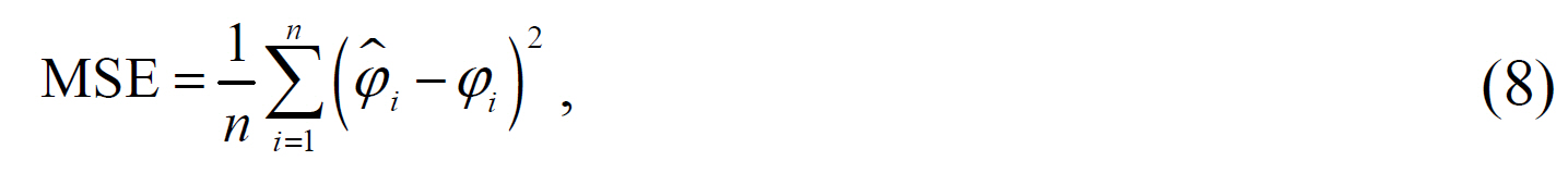
where

and

are the calculated angle and the ground truth angle of the i-th corner (in radians), respectively, and
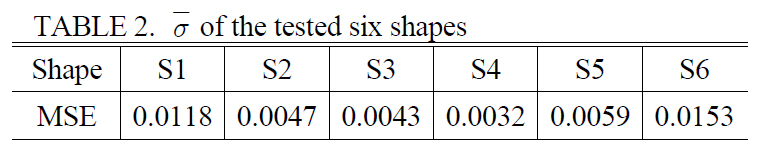
To evaluate the performance with regard to the scale invariant measure, we tested the images with a zoom of 2x and 4x with the same parameters (

of the tested
[TABLE 1.] MSE of the tested six shapes

MSE of the tested six shapes
[TABLE 2.] of the tested six shapes

of the tested six shapes
shapes is very low, as shown in Table 2. Previous methods,however, were very sensitive to scale parameters, so that the corners could not be reliably detected.
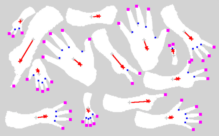
To evaluate the performance for complex shapes, we tested our method for fingertip detection. The original images were binarized using color differences. The partial circles were generated using
This paper proposes a novel method which detects convex and concave corners by using radial projection. The corner angle is calculated using the sum of two neighbor differences at the local maxima or minima of the radial projection function. The use of oriented bounding box trees and partial circles enables the detection of the corners of complex shapes. Moreover, this method can detect the same corners of scaled and rotated images with the same parameters.Therefore, the proposed method may play a strong role in corner detection, image matching, and other applications.