During recent years, plasmonics has been presented as a future technology in integrated circuits incorporating the compactness of electronics and wide bandwidth created by current optical networks [1]. In the region of integrated optics, plasmonic waveguides act as components to guide optical signals to different parts of the circuits. The capability of confining light beyond the diffraction limit and the ability to fabricate devices with dimensions below 100 nm has promised an evolution in optoelectronic circuits [2]. To guide plasmonic waves for various applications, different geometries have been proposed such as dielectric-loaded surface plasmon polariton waveguides [3], nanostructured plasmonic substrates for enhanced optical biosensing [4], tunable coupled-ring reflector laser diodes [5], dielectric gratings on flat metal surfaces [6, 7], Metal-Insulator-Metal waveguides [8, 9] nano-wires [10, 11], chains of nano-particles [12-14], grooves and wedges [15, 16], etc. Although some of these nano-guides are inconvenient to implement in optical circuits, MIM waveguides have attracted considerable attention due to simplicity in fabrication and strong field confinement [17].
During recent years, some simple structures have been suggested for plasmonic filters including channel drop filters with disk resonators [18], rectangular geometry resonators[19, 20], and ring resonators [18, 21]. In comparison with complex structures of Bragg reflectors, the aforementioned structures can be fabricated much more easily. Two typical types of plasmonic filters in MIM waveguides are band-pass and band-stop filters. In band-stop filters, majority of the input light spectrum is allowed to pass through the filter and only several wavelengths are prohibited from propagation in the structure. But, the band-pass filters let just some specific wavelengths pass through them and reject the majority of the input light spectrum.
One of the most interesting features of filters is to have tunable resonance wavelengths. In previous works, by varying the outer dimensions of the structure, i.e. cavity length or radius, tunable filters were achieved [21-23]. But in this paper, we want to tune the resonant wavelengths of circular ring resonator plasmonic filters, without changing the outer size of the structure. Here, by replacing a portion of the ring core with air, we show that tuning characteristics can be attained. As we know, according to some significant limitations on circuit components’ dimensions, it may not be possible to enlarge the size of the ring resonator to reach to longer resonant wavelengths. Therefore the new method is beneficial for miniaturizing the filters in the case of integrated circuits. The transmittance characteristics of the proposed filter are presented by 2D FDTD method.
This paper is organized as follows. In Section 2, the fundamental propagation mode of the MIM waveguide is reviewed. In Section 3, firstly a simple band-pass waveguide filter with a circular ring resonator is examined and then, to reach a tunable band-pass filter, a hollow-core ring resonator is introduced. The impact of hollowing out the core of the ring resonator is studied for a band-stop plasmonic filter in Section 4. Finally, Section 5 concludes the paper.
II. DISPERSION RELATION AND EFFECTIVE REFRACTIVE INDEX OF MIM WAVEGUIDE
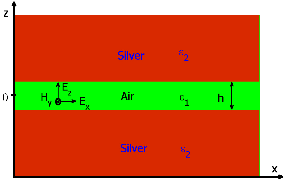
Consider an MIM waveguide structure shown in figure 1. Each of the metal-dielectric interfaces of the waveguide supports a Transverse Magnetic (TM) SPPs mode which propagates along the

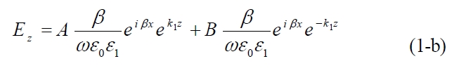
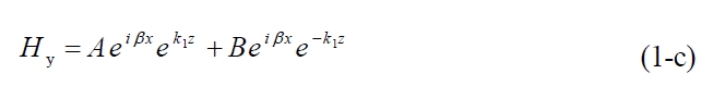
where
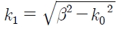
is the wave-vector perpendicular to the propagation direction (
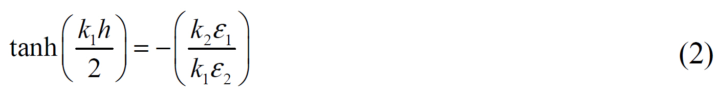
Indices 1 and 2 are pointing to dielectric layer and metal slabs, respectively. In order to characterize the dielectric constant of the metal (silver in this study) the seven-pole Drude-Lorentz model is employed. The fitting model is described as [27, 28]
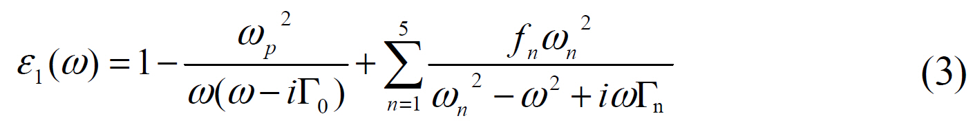
where Г0 = 11.5907 THz is the damping constant and ωp= 2002.6 THz is the plasma frequency. The quantities of resonant frequencies ωn, damping constants Гn and oscillator strength
[TABLE 1.] Values of the Drude?Lorentz model parameters(metal is assumed to be silver)[27 28]
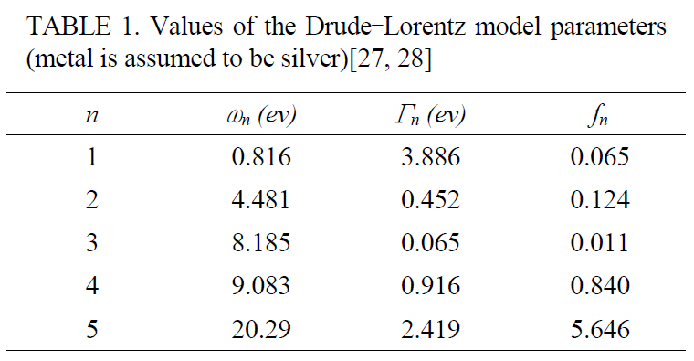
Values of the Drude?Lorentz model parameters(metal is assumed to be silver)[27 28]
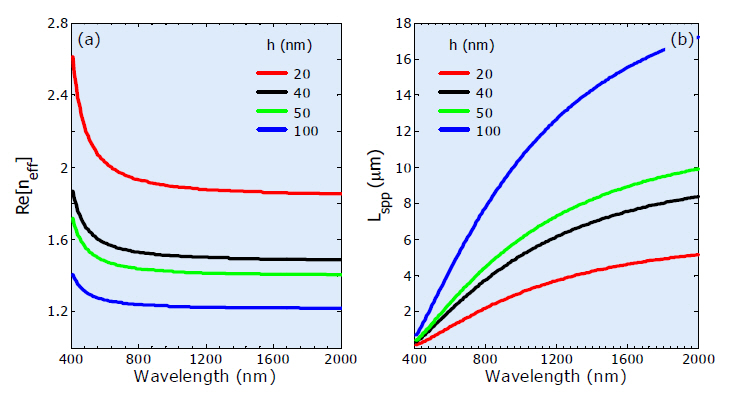
We have analytically calculated the effective refraction index (
III. BAND-PASS PLASMONIC FILTER WITH CIRCULAR RING RESONATOR
3.1. Simple Band-pass Waveguide Filter with Circular Ring Resonator
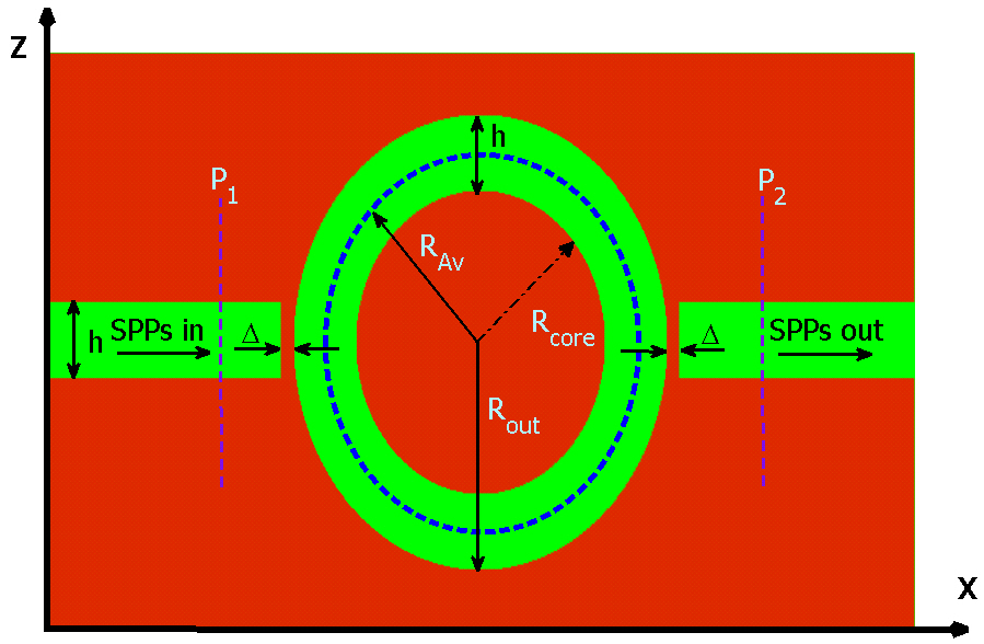
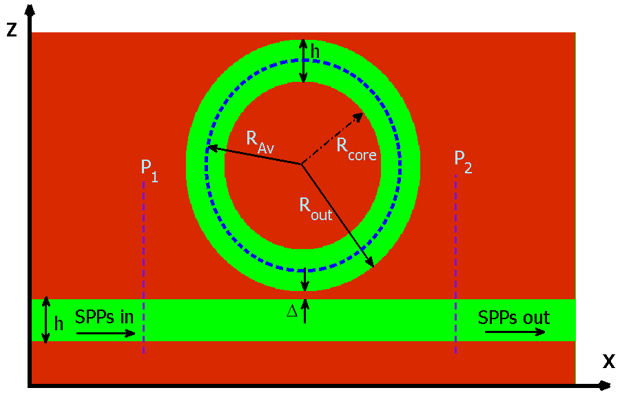
Figure 3 shows the structure of a simple band-pass plasmonic filter which consists of two MIM waveguides coupled to each other by a circular ring resonator, which was first described in Ref [21]. The filter parameters h, Δ, Rcore, RAv, and Rout are the width of MIM waveguide, the gap distance between input/output MIM waveguides and circular ring resonator, the radius of core, the average radius of the ring and the outer radius of the ring resonator, respectively. We set
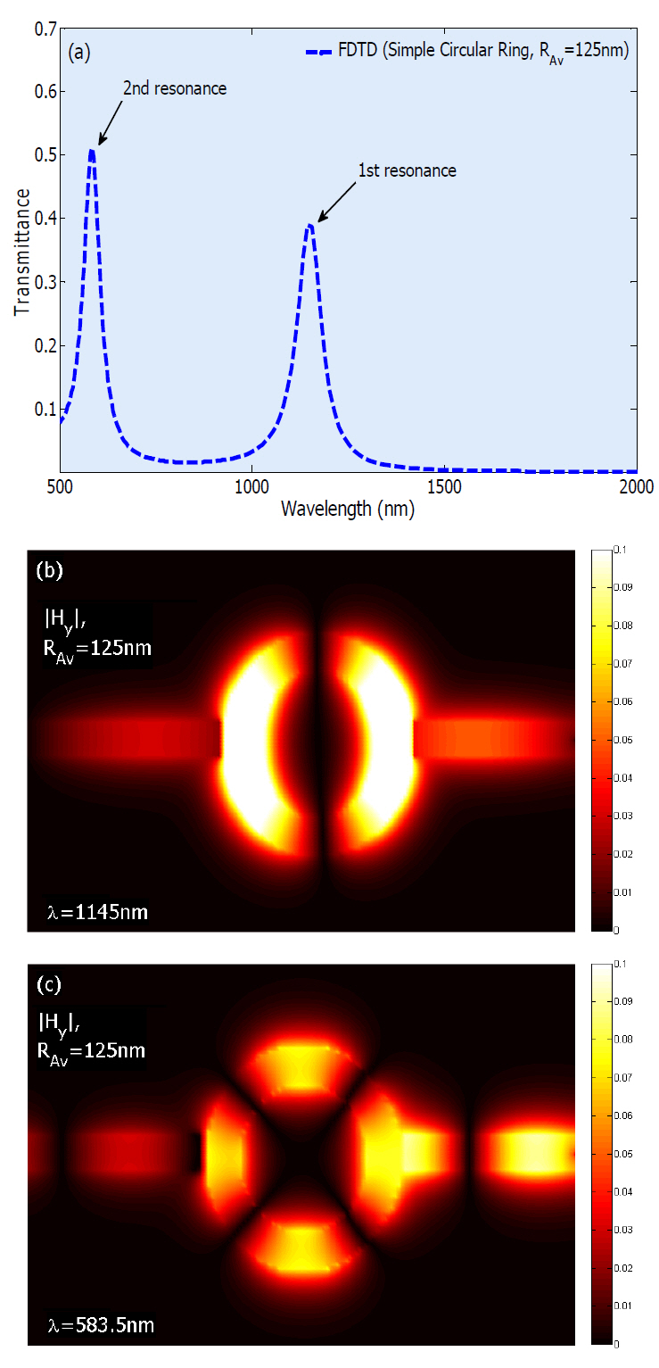
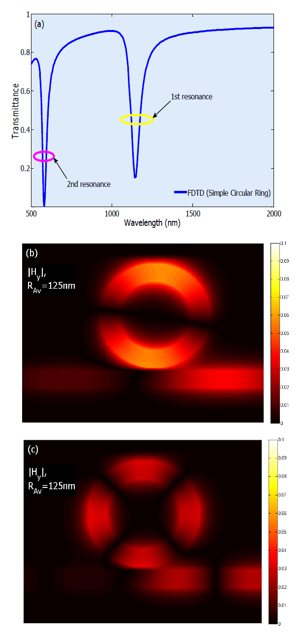
Two power monitors are set at points P1 and P2 to detect the input power A1 (without the circular ring resonator) and the transmitted power A2 (with the circular ring resonator). So, the power transmittance is T = A2/A1[21, 27]. The transmittance of the filter is shownin figure 4(a), assuming
where
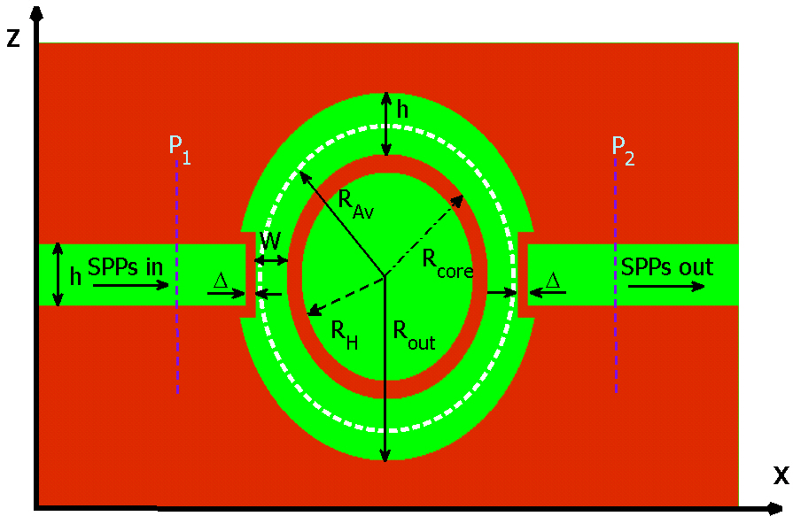
3.2. Band-pass Plasmonic Filter with Hollow-core Ring Resonator
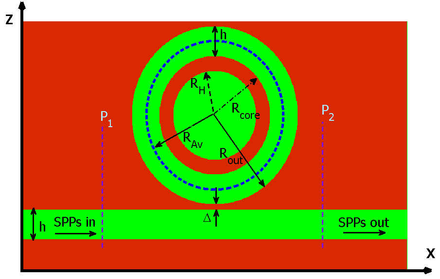
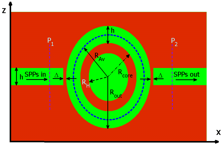
In this section, we investigate the effect of hollowing out the core of the ring resonator on resonance wavelengths of the band-pass filter while keeping its outer dimensions constant (i.e. RAv, h and Δ are kept constant). The proposed structure is depicted in figure 5. From the figure one can see that the core of the ring resonator is emptied with the radius of RH.
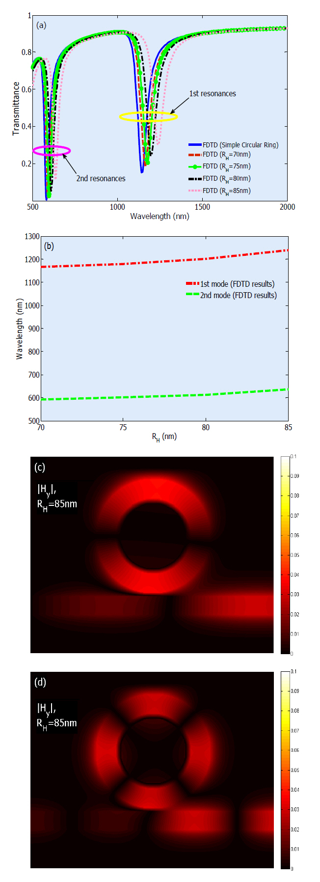
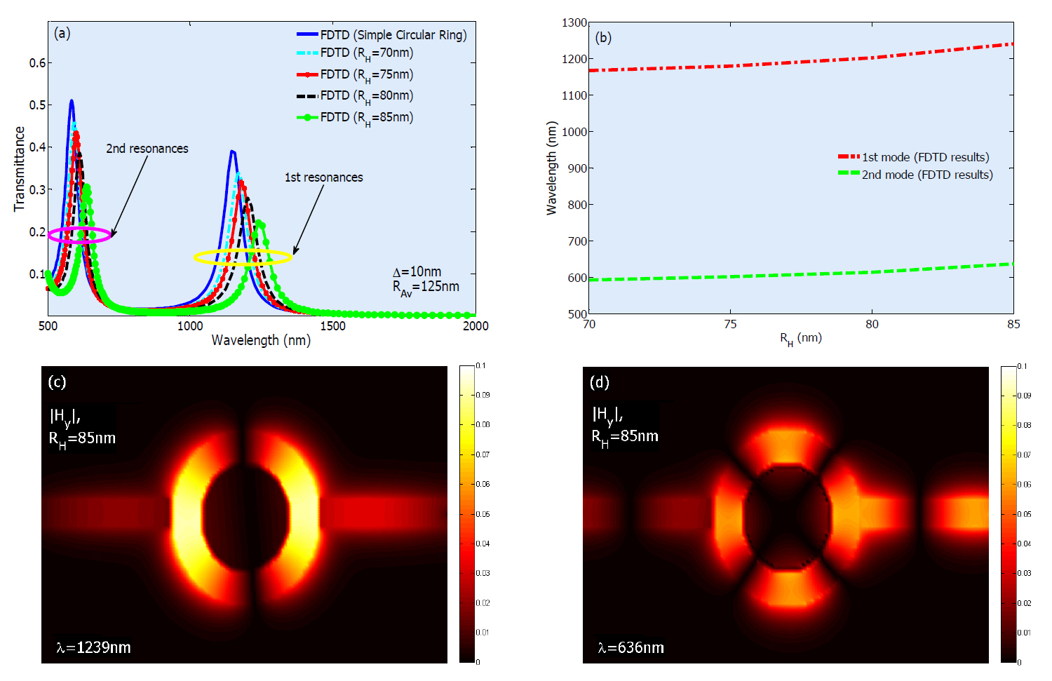
Now, we look into the effect of varying RH on shifting the
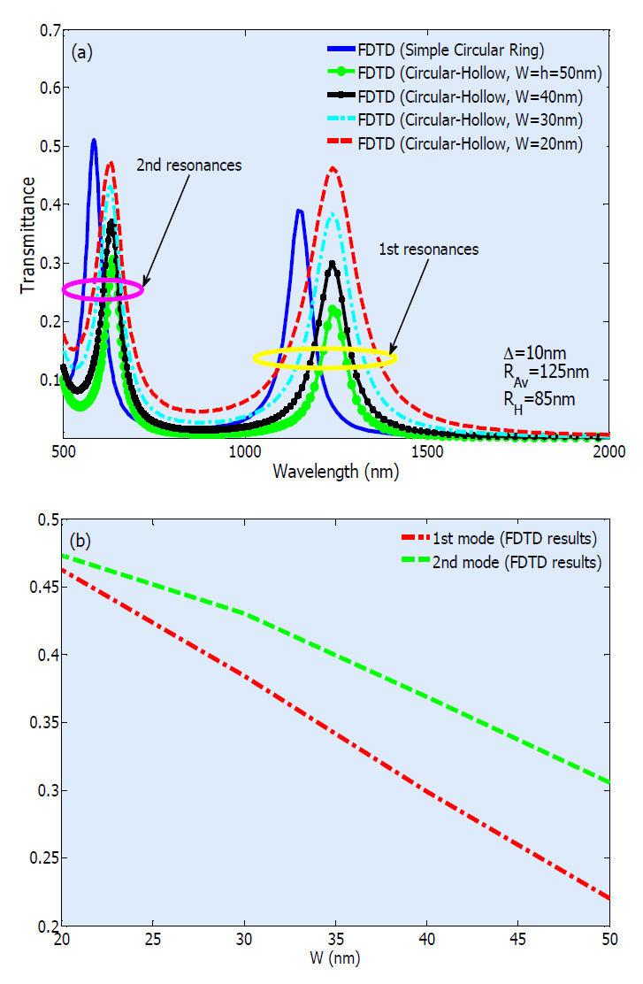
resonant wavelengths of the band-pass filter. The transmittance spectra of the proposed structure is calculated by 2D-FDTD and illustrated in figure 6(a). One can see that by increasing RH from 70 nm to 85 nm, the entire transmission spectrum experiences a red-shift. Figure 6(b) shows that the wavelengthshifts of modes 1 and 2 behave approximately linearly with respect to variation of RH. This result is in complete accordance with the physical fact that by increasing the resonance volume, resonant wavelength will be increased. According to the transmission curves illustrated in figure 6(a), it is clear that the band-pass filter can be easily tuned by adjusting RH.
3.3. Enhancing the Transmittance Peak
It is seen from figure 6(a) that by increasing RH, the maximum value of the transmittance peak declines. To enhance the transmittance, we decrease the width of ring MIM waveguide in the coupling region. The proposed structure is depicted in figure 7. The procedure of transmittance increment versus W is illustrated in figure 8(a) for first and second resonance modes of the structure. It is obvious from the figure that the first resonance wavelength has experienced no shifting by varying W, but the second mode is slightly blue-shifted (Δλ?7 nm) with respect to decreasing W. The relation between decreasing the W and increment of transmittance for first and second modes is shown in figure 8(b). As can be
seen from this figure by decreasing W, the coupling area between input/output MIM and ring MIM waveguides increases and therefore more power will be transmitted.
IV. BAND-STOP PLASMONIC FILTER WITH CIRCULAR RING RESONATOR
4.1. Simple Band-stop Waveguide Filter with Circular Ring Resonator
Another essential and useful component for photonic circuits is a band-stop filter. Figure 9 depicts the geometry of a simple band-stop plasmonic filter which consists of an MIM waveguide laterally coupled to a circular ring resonator. The filter parameters h, Δ, Rcore, RAv, and Rout are the same as for the band-pass filter.
Two power monitors are set at points P1 and P2 to observe the incident power A1 and the transferred power A2. The transmittance of the filter with
4.2. Band-stop Plasmonic Filter with Hollow-core Ring Resonator
In this part, by keeping constant the outer dimensions of the band-stop filter (i.e. RAv, h and Δ) and hollowing out the core of the ring resonator (see Fig. 11); we check how the resonant wavelengths of the filter will be affected.
As for the band-pass filter case, we anticipate that by increasing RH, the resonant wavelengths of the band-stop filter experience a red-shift. This case is illustrated in figure 12(a). One can see that by varying RH from 70 nm to 85 nm,the entire transmission spectrum has undergone a red-shift. Figure 12(b) shows that the wavelength-shifts of the modes 1 and 2 have approximately lineal relations with respect to
the variation of hollow radius. This effect is in complete agreement with the case for band-pass filters, i.e. by increasing the resonance volume, the resonant wavelength is increased.So, from the transmittance curves, it is explicit that by altering the RH, the band-stop filter can be simply adjusted.
In this paper, firstly the propagation characteristics of a band-pass filter composed of two MIM waveguides coupled to each other by a circular ring resonator were studied. To make the proposed filter tunable, an easy way of emptying the core of the ring was introduced and investigated numerically. Then, a band-stop filter consisting of an MIM waveguide laterally coupled to a circular ring resonator was studied and the impact of hollowing out the core of this ring resonator was investigated. It was seen that for both cases, by increasing the radius of the hollow, the resonant wavelengths of the structures experienced a red-shift. A significant advantage of the proposed method of making filters tunable is ease of fabrication. The resonant modes of the structures were calculated by FDTD and it was found that we can easily manipulate the central wavelengths of the resonance transmission by tuning the radius of the hollow while the outer dimensions of the ring are kept constant. The introduced structures can decrease plasmonic filter dimensions and so are potentially a choice for designing of all-optical integrated circuits for optical communication and optoelectronic circuits.


![Values of the Drude?Lorentz model parameters(metal is assumed to be silver)[27 28]](http://oak.go.kr/repository/journal/10700/E1OSAB_2011_v15n1_82_t001.jpg)