Stray light implies incoherent light that does not follow the normal optical path. These unwanted rays reaching the detector’s surface degrade the image quality of the optical system and sometimes generate a ghost. In many fields of application such as precision cameras, microscopes, spectrometers, displays, and nano-scale photolithography, the importance of stray light analysis has increased to prevent risk of increased redesign cost [1-3]. Moreover, even a slight design mistake is difficult to tolerate for an optical system in an artificial satellite because it cannot be changed or modified once the satellite has been launched. With the recent progress in space technology, the resolution of spaceborne electro-optical camera systems is getting more competitive. Therefore, the cancellation of stray light is being recognized as a key technology for achieving a better resolution of the optical system loaded on a satellite for earth observation. During earth watching by an electrooptical payload on a LEO(Low Earth Orbit) satellite, the imaging quality can be accidentally disturbed by illumination sources created by abnormal angles [4-5]. This stray light can render the signal obscure, reduce visibility, and cause incorrect radiometric results.
The stray light analysis can be approached by several methods such as y, y-bar diagram, Monte Carlo method,and parametric method [6-7]. However, the most common methods of analyzing stray light are radiometry and ray tracing [8-11]. Radiometry calculates the transferred power of stray light from object to object in an optical system. Though it can efficiently get a numerical result for stray light flux, it can supply only limited visualized information.On the other hand, ray tracing can provide not only better computational capability but graphical representation. Therefore, we used a ray tracing method for graphical help in investgating out a stray light problem.
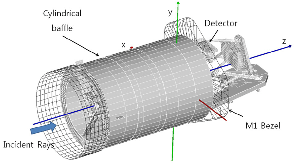
Figure 1 shows the optomechanical unit of a high resolution spaceborne camera as a payload of a low-earth-orbit satellite being developed by Korea Aerospace Research Institute. This electrooptical payload is composed of five mirrors and a detector. The optical geometry has symmetry in one direction; however, M5, the folding mirror, is placed obliquely on the other direction that is perpendicular to the symmetry for bending the ray path to the detector. This geometry is favorable for a compact volume design and an additional optical channel afterward when M5 is replaced with a beam splitter. Miniaturization and mechanical durability are key factors in the payload design because it should be able to overcome the heavy vibration and gravitational force when it is launched. Folding the optical path reduces the entire structure volume and increases the mechanical tolerance. The incident beam travels along M1~M5 in numerical order before reaching the detector surface. The incident light goes into the cylindrical baffle guiding rays to M1 and then it is then reflected onto M2. The reflected beam goes on continuously reducing the beam radius to pass through a hole at the M1 center. After passing through the hole, the beam expands the radius and heads for M3. The beam is reflected by M3 and M4 in order, and makes a right angle turn to the detector by M5. Finally, the detector collects the signal.
In mechanical geometry, the M1 bezel and cylindrical baffle construct the frame of this spaceborne camera. They support other mechanical parts such as vanes, bezel, and trusses to fix and stabilize the mirrors and a detector.
In this study, we investigated the effect of stray light on imaging quality of the KARI payload. A stray light analysis is performed to investigate where and how much effect stray light can have. A scattering model is also applied to inspect the variation of spot flux on the detector surface.
Stray light analysis was performed on the spaceborne camera that is the payload of a KARI’s LEO satellite to determine how unwanted light gets to the detector, as well as how much bad influence stray light has on it. The procedure of stray light analysis starts from finding critical objects. The critical objects are any faces and edges that can be seen by the detector through the optical components. The critical objects fully reflect the scattering light reaching to the detector in the spaceborne camera of KARI. Illuminated objects are objects illuminated by external light sources from an unexpected incident angle. Both critical and illuminated objects are the first order stray light sources of the detector. Therefore, the analysis of stray light for the spaceborne camera of KARI starts from finding both the critical and illuminated objects.
The first step for stray light analysis is finding the critical objects. The rays start from the detector surface to the optical system in the opposite direction of normal ray tracing. The detector performs a role of a surface light source. However,the surface light source can have many point light sources and its number and acceptance angle play a prominent role for the calculated result. Therefore, we performed early work to fix the important edges that limit the field of view of the point light source on the detector surface. This work was helpful to make the search efficient by eliminating unnecessary rays.
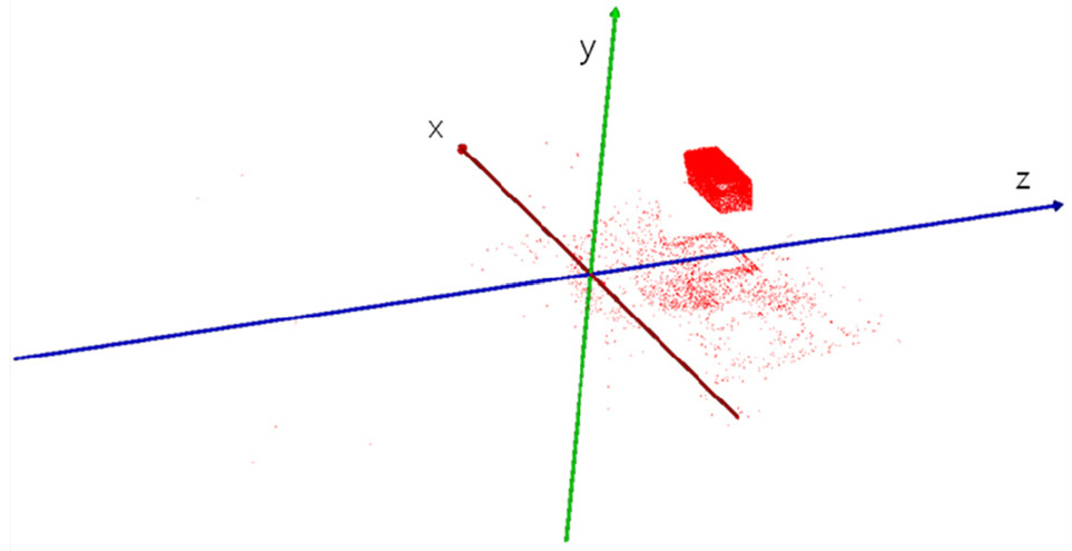
Figure 2 represents the top 100 candidates for the critical objects. Most candidates are objects in the course of the normal optical path. Most rays hit the detector baffle and window parts denoted by a dark cube in fig. 2. The second prominent object was the mount of M5 denoted by a less dense rectangle below the dark cube.
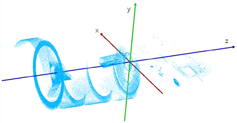
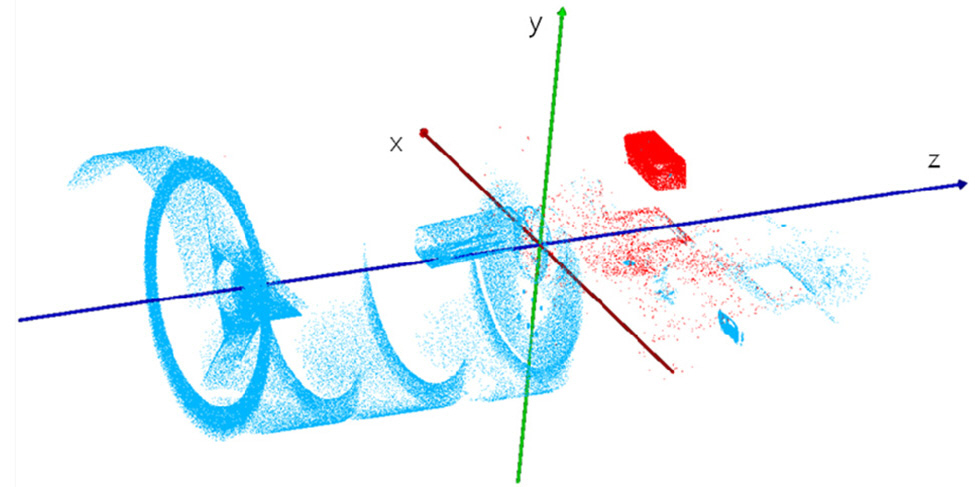
Illuminated objects are objects that the external rays reach. External lights such as a distant star can go into the optical system from off axis of the normal incident direction, and they can create illuminated objects in the optical system. These illuminated objects may generate rays that can reach to the detector along abnormal optical paths. In the spaceborne camera of KARI, the external light from the off-axis of the y-direction is more important than that of the x-direction because the geometry of the camera has symmetry in the x-axis and the beam direction is supposed to be bent to the positive y-direction by M5. As shown in fig. 3, most rays are blocked by the M1 baffle and bezel,except some rays reaching the structures behind the M1 bezel. Three thick solid lines denote the geometrical axes.
2.3. Sorting Out Stray Light Sources
Objects classified both as critical and illuminated are stray light sources that can create noise on the detector. In our analysis, most stray light paths were blocked with the appropriate structures such as baffle, vane, and stops. Figure 4 depicts all critical and illuminated objects as candidates for stray light sources.
As a result, there is no strong candidate for a stray light source, except the objects on the normal optical path. However, in an imaging system, scattered light analysis is necessary if any incorrect light could reach the detector surface.
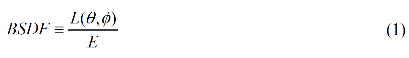
As shown in the stray light analysis, the illuminated objects can spread light into a desired optical path and obscure a faint image. If any surfaces of stray light sources in the spaceborne camera of KARI have scattering properties, then they should be examined to determine how much the scattered light mixes their flux into the signal. In this study, we employed a scattering model in terms of a Bidirectional Scattering Distribution Function (BSDF). Assuming that the scattered power is linearly related with incident power, BSDF is defined as a function of radiance,
Where,
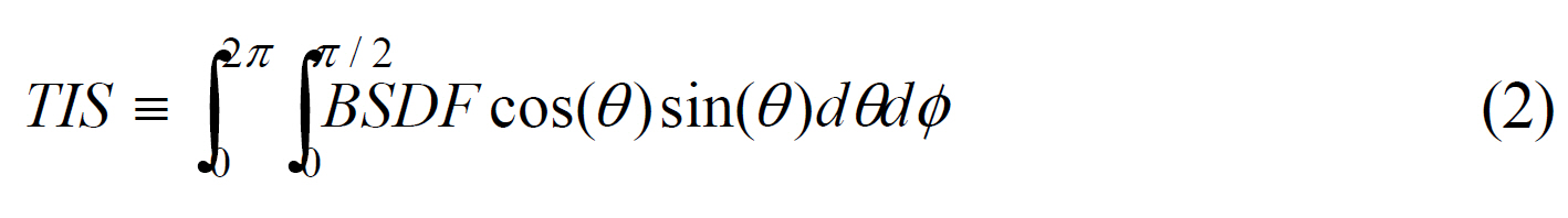
According to the two factors of BSDF and TIS, the scattered rays could be simulated for every surface in the optical system. However, accuracy of the scattering simulation depends on how close the scattering surface described is to a real situation. The Harvey model was chosen to estimate scattering characteristics because it states well the scattering of optically polished surfaces such as mirrors.
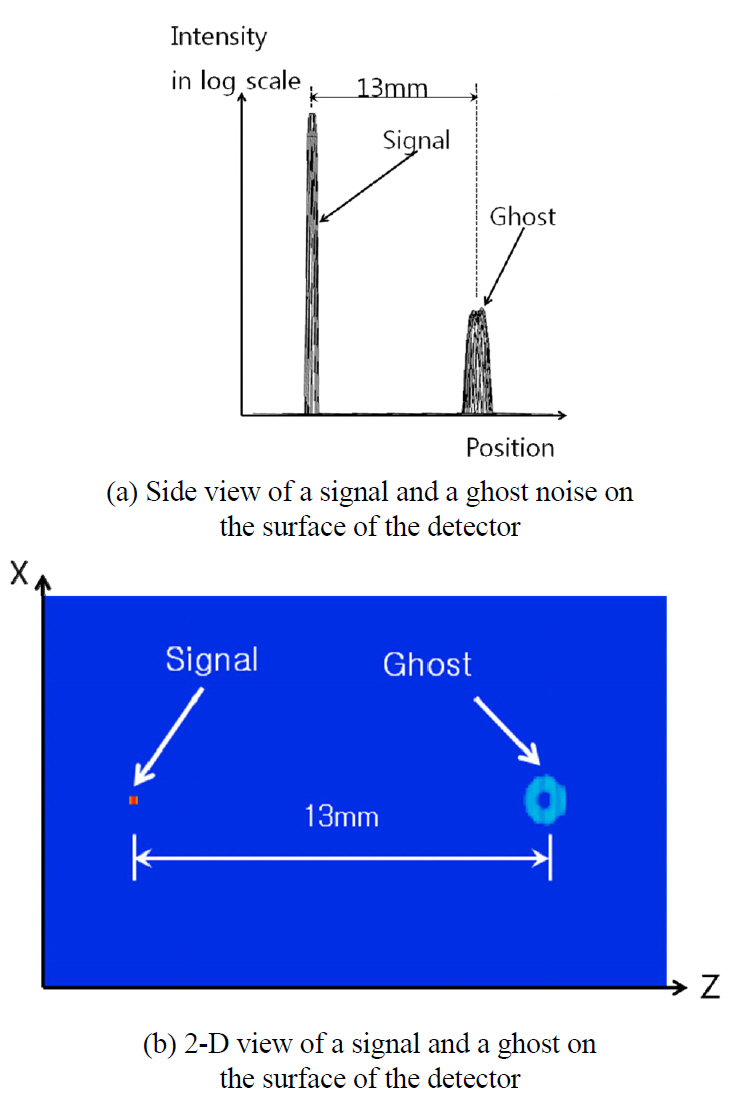
Figure 5 is a 2-D and a 3-D view of a signal and scattered ghost noise on the surface of a detector when all optical surfaces have scattering properties and the reflectivity of M5 is 0.5. The ghost noise was generated by rear reflection of M5. Intensity is magnified in the log scale for easy readout. The real relative flux of a signal was calculated using the reflectivity of M5, because M5 can be replaced by a beam splitter. In that case the transmitted rays can be used for an additional optical channel along the z-direction. The noise was not significant until the reflectivity of M5 had reached 0.5.
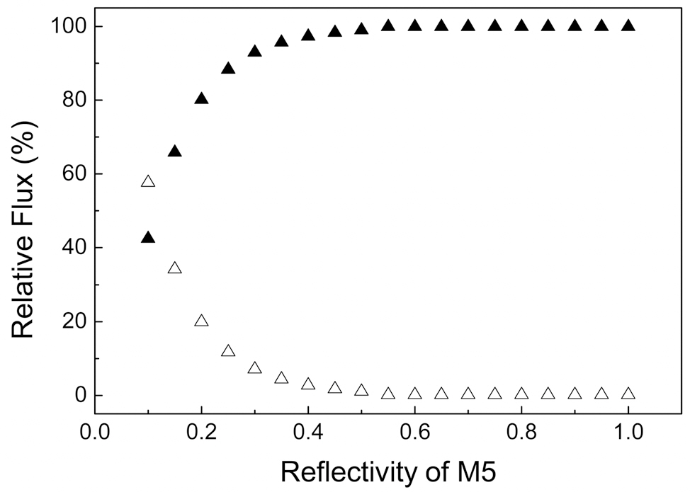
The relative flux of a signal and a noise as a function of reflectivity of M5 was calculated as shown in Fig. 6, because M5 is the only optical element in the KARI spaceborne camera that can have different reflectivity for the additional optical channel. Though the relative flux cannot represent where the noise is formed on the detector surface, it can show the magnitude of the noise effect on the detector as a function of the reflectivity of M5. As shown in Fig. 6, the relative flux of noise keeps a nearly constant value until the reflectivity of M5 reaches 0.5. In the range of reflectivity that is lower than 0.5, the relative flux of a signal and noise shows noticeable change. The calculation result implies that the relative flux of signal is invariable until the reflectivity of M5 reaches 0.5, but the signal intensity weakens.
As a result of the recent increase in demand for earth surface information in the fields of global positioning systems and intelligence satellites, the quality of photograph technology has been improved. Cancellation of stray light is a key technology to improving image quality. We investigated the effect of stray light on imaging capacity of the spaceborne camera developed in Korea Aerospace Research Institute, and the effect of M5 reflectivity is also analyzed with scattering modeling. The calculated results showed noise spot formation on the detector surface and the relative flux of signal and noise. The stable range of reflectivity of M5 and trend of noise flux are also suggested in this paper. This analyzing method is very necessary because it prevents costly redesigns or uncorrectable mistakes. In this paper we proposed a procedure for analyzing the stray light of optical systems and we employed scatter modeling to find the noise spot on a the detector surface. A methodology for analyzing optical system like that in this paper is applicable for improving precision in optical apparatus and systems.