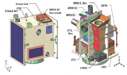
The objectives of Science and Technology Satellite-3(STSAT-3) showed in the figure 1 are to optimize technologies proven through the previous small satellite program developed by Satellite Technology Research Center, Korea Advanced Institute of Science and Technology (SaTReC KAIST) to demonstrate the advanced spacecraft bus and payload technologies, and to train employees of the space technology fields. The main payloads of STSAT-3 are: Multi-purpose Infrared Imaging System (MIRIS) and the Compact Imaging Spectrometer (COMIS). The MIRIS system is to measure infrared (IR) imaging of the Galaxy (at 1-2㎛ wavelengths)and COMIS is to observe the hyper-spectral imaging of the Earth’s surface (in the visible and near IR bands at 0.4~1.05㎛ wavelengths). The advanced spacecraft bus technologies which are to be proven through STSAT-3 in the space consist of six items: 1) Li-ion battery, 2) multifunctional complex structure, 3) high performance on-board computer, 4) small solar power control regulator, 5) hall thrusters, 6) array antenna (Korea Aerospace Research Institute, 2007).
The ground station of STSAT-3 provides the capability to monitor and control STSAT-3, to conduct STSAT-3 mission planning, and to receive, process, and distribute STSAT-3 payload data to satisfy the overall missions of STSAT-3 (Korea Aerospace Research Institute, 2008).[Ed: Please ensure when formatting finished document that all columns end in appropriate places. For example, at the end of a page.]
The ground station consists of the mission control element(MCE) and the data receiving element (DRE). In this paper,the requirement and design of the ground station which is being developed are examined.
The goal of the ground station development for STSAT-3 is to control STSAT-3 for its successful mission using the low cost and the high efficiency concept. For this goal, the MCE and DRE will be re-used or upgraded with the STSAT-2 ground station heritage. The ground station of the SaTReC KAIST has accumulated its heritage through ground station development for five low earth orbit micro satellites and the operation of four low earth orbit micro satellites since 1992.
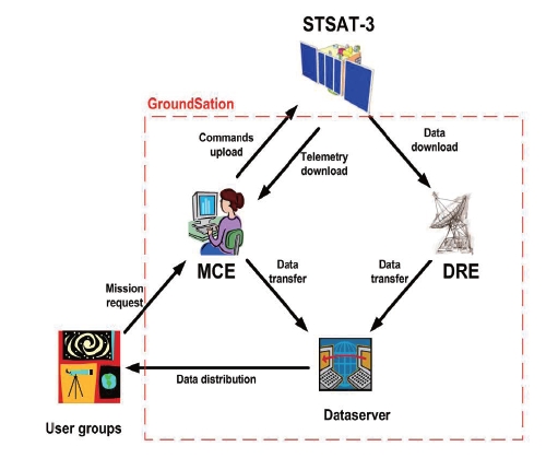
Figure 2 shows the basic operational concept of the ground station for STSAT-3 and the payload user groups. In the figure, user groups request the mission to the MCE. Next,the MCE verifies the requests, converts them into command sequences, and uploads to STSAT-3. After carrying out the mission, STSAT-3 downloads the measured mission data to the DRE. The DRE archives the downloaded data and then transfers to the data server. The user groups finally obtain the distributed data and utilize the data for their research.
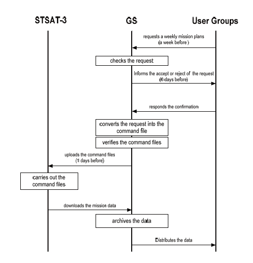
Figure 3 shows a more detailed mission operational concept. The user groups of the MIRIS and the COMIS request a weekly mission plans to the ground station at least seven days before. The ground station checks the validation of the mission plans based on the status of STSAT-3 and then informs the user groups of acceptance or rejection.The user groups confirm and respond with the result to the ground station. The ground station converts the request into command files. The command files are simulated, validated,reviewed, approved, and finally uploaded to STSAT-3 at least one day before.
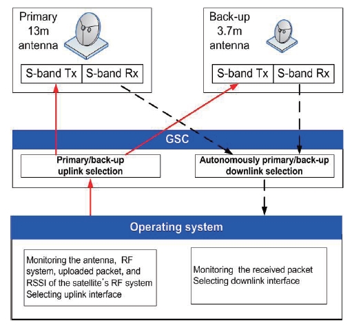
For safe operation of the mission, the ground station is designed with the concept of primary and back-up tracking,telemetry and command (TT&C) systems. Figure 4 shows the conceptual design of the TT&C system. This TT&C system consists of three parts: 1) the antenna subsystem, 2) radiofrequency(RF) subsystem, 3) base-band subsystem (ground station controller, GSC). This GSC, which has the base-band functions, is designed for autonomously selecting one of the primary downlink and the back-up downlink of the TT&C systems by monitoring the packet count received from STSAT-3. This concept is useful for efficiently receiving the data of the satellite using two TT&C systems simultaneously.In case of the uplink, the operator can select one by controlling the GSC after monitoring the status of two TT&C uplink systems, and the radio signal strength index (RSSI) of STSAT-3.
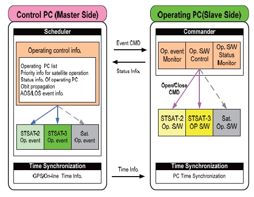
The ground station, which is designed with the concept for the low cost and high efficiency, is re-used and upgraded from the previous ground station. Further, because all of the STSAT-2 and STSAT-3 should be operated together,this ground station should be designed for simultaneous operation. To meet this condition, the software integrated control scheme studied by Bester et al. (2003) is considered.The scheme shown in the Fig. 5 can operate two satellites with one ground station. This scheme consists of one control PC and several operating PCs for the STSAT-2 and STSAT-3.Each operating PC has unique operating programs for each satellite. The control PC can autonomously control each operating PC based on a control list such as the contact time information of the satellite, periodic time synchronization and the orbital information. This scheme also includes the external network for the control PC, and the closed loop network for the operating PCs for their security.
2.2 Architecture of the ground station
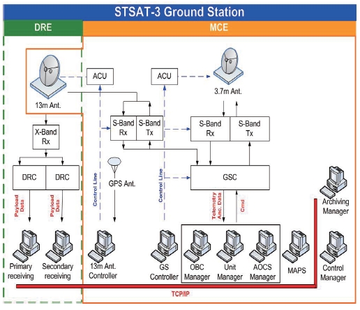
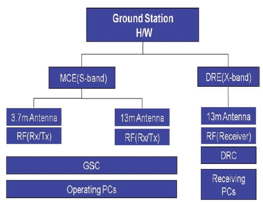
The architecture of the ground station is shown in Fig.6The ground station has two antennas: 1) 13 m X/S-band antenna, 2) 3.7 m S-band antenna. The current 13 m parabolic reflector antenna can download X-band and S-band signals,but will be upgraded to upload S-band signals as a primary antenna system. The 3.7 m parabolic reflector antenna system can upload and download S-band signals as a full duplex back-up antenna system. The 3.7 m antenna is to be re-used from the existent system. Two antenna systems are efficient for safely operating the satellite. The ground station consists of the MCE for controlling the satellite and the DRE for receiving the mission data. The hardware block diagram and the software block diagram of the ground station are shown in Figs. 7 and 8 respectively.
2.2.1 Design of the hardware
The hardware system consists of the antenna subsystem,RF subsystem, base-band subsystem (GSC; data receiving controller [DRC]), and operating computer subsystem.These antenna subsystems can track satellites via manual,program, and auto modes, transmit command and flight S/W to satellites with the S-band uplink, receive telemetry and ancillary data from satellites with S-band downlink,and receive the mission data with X-band downlink. The RF subsystem can modulate and transmit the S-band signal,and receive and demodulate the S-band/X-band signal. The GSC can modulate and demodulate into FM/FSK with 9.6 and 38.4 Kbps data rates. It is also capable of data formatting,path control, and remote control. The DRC can handle 16 Mbps data rate and demodulate the QPSK signal for the mission data. The Control PCs to operate the satellite and the receiving PCs to download and archive the payload data operate on Microsoft Windows XP.
2.2.2 Design of the software
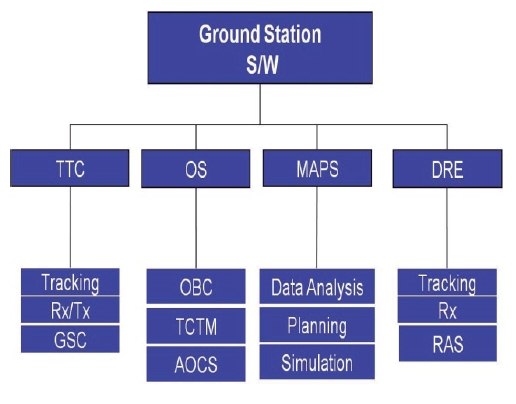
As illustrated in Fig. 8,the software system consists of, OS, mission analysis, planning, and simulation (MAPS), and DRE. The TTC can control TT&C hardware autonomously both in real-time and off-line. The TTC also includes the functions for controlling tracking, Rx/Tx, and GSC. The tracking program can control antenna tracking. The Rx/Tx can monitor the status of the RF signal and control the Doppler shift compensation. The GSC can handle input/output data rates of 9.6 and 38.4 Kbps and control the interface between the antenna system and the operating system.
The OS includes the functions for monitoring and controlling the on-board computer (OBC), telecommand and telemetry (TCTM) and attitude and orbit control subsystem(AOCS) in real-time. The OBC software that controls the satellite in real-time can upload the commands to control the tasks of the satellite and to perform the mission, as well as download the files generated from the satellite. The TCTM software can receive, process, display, and archive the telemetry and upload the raw commands instead of through the on-board computer of the satellite as a contingency.The AOCS software can monitor and control the attitude of the satellite. The MAPS, which has the function of mission planning and analysis, includes the functions of real-time log, status of health (SOH), and STSAT-3 simulation (S3SIM).The function of the real-time log is to monitor the log such as the status of the on-board computer, tasks, and units of the satellite. The SOH has the function of analyzing the telemetry. The S3Sim can verify commands before uploading them and also analyze anomalies detected by the satellite.The DRE software includes the functions of tracking, RX, and receiving and archiving system (RAS). The RAS can receive and archive the mission data.
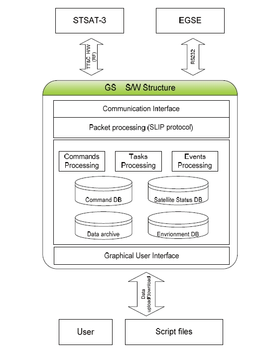
The software of the ground station has a part in common with the software of the electrical ground support equipment(EGSE) to verify the performance of the satellite. To reduce the development time and cost, this common part can be designed together for both the ground station and the
EGSE. This software uses serial line internet protocol (SLIP)protocol for processing the packet.
The S/W structure shown in Fig. 9 includes the following functions:
- Graphical user interface for controlling and monitoring the satellite
- Commands processing
- Task processing including the status of the satellite
- Event processing for monitoring and controlling ground station H/W
- Database managing and data archiving
- Packet processing for the communication interface
This graphical user interface has functions for processing various input data, including user and script-based command files. This script-based interface can perform command file autonomously during the operating time. Thus, its interface can reduce operating errors and replace changed commands easily. The commands processing function provides defined input commands decoding, processing, and verification using the command database. The function also includes raw commands processing for basic commands, single commands processing for each single command, and macro commands processing for multiple commands. The task processing function can monitor and process the telemetry data using the satellite status database. This task processing also has the function of monitoring and controlling the unit,OBC, file, attitude, payload, and scenario of the satellite.The event processing function can monitor and control the
ground station H/W according to acquisition of signal and loss of signal events of the satellite. The packet processing function can process data to transmit and receive the signal through the ground station equipments. This packet processing uses the SLIP protocol for communication.
The ground station has been developed and operated successfully since the SaTReC KAIST was established in 1989.With this heritage, the existent ground station will be re-used and upgraded to reduce the cost, risk, and development time (Kim et al., 2003). The software integrated scheme was considered to make it possible to simultaneously operate more than two satellites with one ground station for cost efficiency. Most of all, it is known that some software of the ground station can be compatible with the EGSE software through previous development experiences. Therefore,these common functions of the software will be able to be developed and used for both the ground station and EGSE(Kim et al., 2008). Consequentially, the ground station software will be developed and verified safely through the development and verification of the EGSE software, and the cost, time and risk from both developments will be reduced considerably.
The performance of the designed ground station will be proven throughout the launch, and early operation of STSAT-3.