The inner-loop autopilot and the outer-loop guidance law are designed separately by spectral separation assumption.However, during the endgame phase of the interceptor, the spectral separation assumption will be not valid due to the rapid change of the engagement geometry. This causes the instability and then increases the miss-distance between the missile and the target. Therefore, the traditional approach to design the autopilot and guidance law separately has the limitation during the endgame phase. In the future, the interceptors will require reducing the miss-distance more efficiently and decreasing the warhead, to decrease their lethal radii. In addition, if the weight of the missile is reduced without decreasing the accuracy of the missile, the cost to produce the missile can also be decreased.
The integrated guidance and control (IGC) system of the missile can improve the performance of the endgame phase after the midcourse phase using the synergism existing between the guidance and control subsystems. For instance,the bandwidth of the autopilot can be optimally adjusted as the guidance of the missile so the accuracy of the missile can be improved. In addition, the IGC system uses the information on the missile states more effectively and can satisfy requirements of the interceptor of the future.
Several nonlinear control methods were applied to design the IGC controller. A sliding mode technique was used to design the IGC controller for a missile with on-off actuators,and a higher-order sliding mode technique was used to design the IGC controller for missiles steered by a combination of aerodynamic lift and thrust (Koren et al., 2008; Shima et al.,2006; Shtessel and Tournes, 2009). Numerical state-dependent riccati equation approach was used to design the integrated controller for moving mass-actuated missiles (Vaddi et al.,2009). In addition, the integrated controller design was carried out using the feedback linearization in conjunction with the linear-quadratic-regulator approach (Menon and Ohlmeyer,2001).
To design the IGC, the robust control method is needed because highly nonlinear uncertainties exist in the missile and the target. A time-delay control (TDC) law is a robust control technique for nonlinear systems, and it has a very simple structure. The characteristic of TDC is to directly estimate the unknown dynamics and the unexpected disturbance using one-step time-delay if the sampling time of the controller is very small. The TDC law was applied to the robot-manipulator control, the trajectory-tracking control of underwater vehicles, and an observer design for DC servo motor, but it was not used to design the IGC controller for the missile (Chang and Lee, 1994; Hsia and Gao, 1990; Prasanth Kumar et al., 2007). The main contribution of this paper is to propose the novel IGC controller using the TDC technique,utilizing the zero-effort miss (ZEM) distance.
This paper is organized as follows. The nonlinear and linearized models are derived, and the TDC law is reviewed next. The IGC controller using the TDC technique is proposed,and then the numerical simulations are performed as the target maneuver. Finally, the conclusions are presented.
A canard controlled missile, which is commonly used in short-range air-to-air missiles, is considered. After the midcourse phase, the missile is assumed to fly with small deviation from a collision course, and then its longitudinal and later motion can be separated independently during the endgame phase. Therefore, the guidance and control problem can be treated as a planar problem. First, the nonlinear kinematics and dynamics are derived, and then the linearized ones are derived to define the ZEM, which is used to design the IGC (Koren et al., 2008; Shima et al.,2006).
2.1 Nonlinear kinematics and dynamics
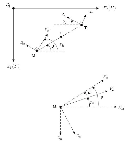
The engagement geometry between the interceptor and the target and the missile coordinate system are shown in
Fig. 1The endgame takes place during the short period so a north-east-down frame can be assumed as a Cartesian inertial reference frame (XI - OI - ZI). In addition, XB ? OB ? ZB is a body-fixed coordinate frame, and XBI - OBI - ZBI is parallel to the inertial reference frame. The subscripts M and T mean the missile and target, respectively. V, γ, and am denote the speed, the flight path angle, and the normal acceleration,respectively. The missile pitch attitude angle and its angle of attack are denoted by θ and α, respectively. r is the relative range between the missile and the target, and λ is the line of sight (LOS) angle.
If the gravitational force is neglected, the engagement kinematics can be expressed in a polar coordinate system.


where the closing speed Vr is

and the speed perpendicular to the LOS is

The time to go tgo is approximated by

The target is assumed to fly with a constant speed during the endgame phase, and its dynamics is regarded as firstorder dynamics:


In Fig. 1(below), the pitch attitude of the missile summing the angle of attack α and the flight path angle is expressed by

The planar missile dynamics can be also expressed as


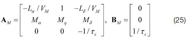
where T is the thrust that is aligned with XB ; L is the lift; D is the drag; m is the mass; I is the moment of inertia; and M is the moment. A canard servo actuator is assumed as a firstorder dynamics model. Therefore, δ is the canard deflection angle; δc is the canard deflection command; and τs is the time constant of the actuator.
During the endgame phase, it is assumed that the missile has no thrust and its speed is constant. Thus, the above planar missile dynamics is more simplified. The lift and moment is expressed by (Koren et al., 2008; Shima et al., 2006)


where LαB=Lα?Ls, MαB=Mα?Mδ, and f is used as saturation function to express the characteristics of the nonlinear aerodynamics characteristics:
2.2 Linearized kinematics and dynamics
It is hard to express the ZEM using the full nonlinear kinematics and dynamics. Therefore, the linearized kinematics and dynamics are needed and the linearization is performed from the initial LOS at the beginning phase of the endgame.
The state vector of the engagement kinematics is defined by

Here, z and ? is the relative displacement and its rate between the target and missile normal to the initial LOS,respectively. In addition, aTN and aMN are the target and missile accelerations normal to the LOS, respectively:


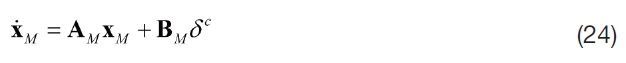
where the subscript 0 denotes the initial values. The dynamics of the missile is approximated by an equivalent first-order system with the time constant τM. As a result, the linearized endgame kinematics is given by

where

and ac TN and ac MN the target and missile acceleration commands normal to the initial LOS, respectively.
The linear missile dynamics are expressed by the following state vector
and the short-period motion is only considered.Therefore, the linear model is given by
where
and
Therefore, the kinematic and dynamic model to design IGC system is described by the following state vector

This model is given by

where
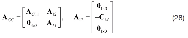


The matrices A
ZEM is defined to be the distance the interceptor would miss the target if the target continued along its present course and the missile made no further corrective maneuvers(Zarchan, 1997). The ZEM has an advantage that reduces the n-dimensional guidance problem to a scalar one. Deriving the ZEM analytically is very complicated using the full nonlinear model, so the linearized model derived previously is used. However, the derivative of the ZEM is determined from the nonlinear kinematics and dynamics model. The ZEM can be derived from the homogenous solution of the linearized integrated dynamics:
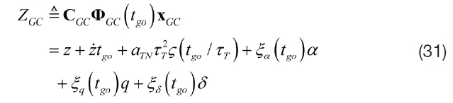
where

and ξα(tgo), ξq(tgo), and ξδ(tgo) are complicated function so their function values are obtained by computing numerically the state transition matrix ΦGC (tgo).

where


We assume that all states related to the problem are measureable and the target acceleration aTN can be also estimated.
This section briefly reviews a TDC law. In Hsia and Gao(1990), the TDC law for robotic manipulator was derived.Consider the following second order dynamics.

where is the state vector; x is the inertial matrix; M(x) is the corioli and centrifugal force; V(x, ?) is a vector function of the gravitational force; G(x) is friction and unmodeled nonlinearities; and D(x, ? ) is the control input.
The control objective satisfies a closed-loop error equation:

where ed(=xd-x) is the error states; xd, ?d, and ?d are the desired trajectories; and Kv and Kp are the control gains.
Adding the bounded constant inertial matrix M? , which should be designed, into Eq. (37), we obtain

and the rearranged Eq. (39) is

where h includes highly nonlinear uncertainties and is defined as

If the sampling time L for the TDC law is very small, the current h can be estimated as follows:

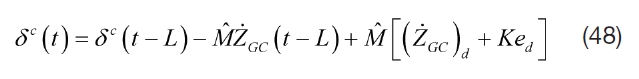
Therefore, the TDC law can be derived as follows:

According to Hsia and Gao (1990), to guarantee that the control system is stable, the constant matrix M? should be designed as follows:

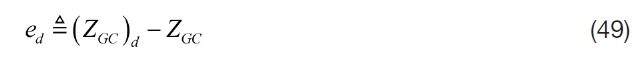
and
In this paper, we want to control the ZEM. The relative degree of the ZEM is one so the first-order dynamics is considered, and TDC law can be simplified to design the IGC system as follows:

The model input is the canard actuator command δc,and the relative degree of the ZEM to the input is one. The target acceleration command acTN is treated as a disturbance.Therefore, to design the IGC controller using TDC technique,the first-order derivative of the ZEM is needed. By differentiating the ZEM defined in Eq. (33), we obtain
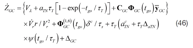
where ?GC=AGCX-GC, 'ΔaTN'<Δ-aTN is the bounded target dynamics error, and 'ΔGC'<Δ-TN is the bounded modeling errors.
Rearranging Eq. (46) to apply the TDC technique, we obtain
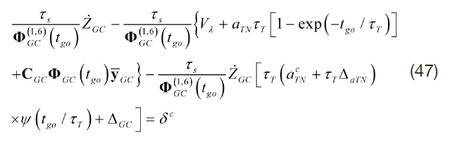
Therefore, the integrated controller is defined as
where
To investigate the performance of the proposed IGC controller using the TDC technique, the numerical simulations of several cases are performed. The first case considers that the target is stationary. The second and third cases consider the moving target with no evasive maneuver and a square-wave (“bang-bang”) evasive maneuver, which has a time period of ΔT s and a time shift of Δφ s relative to the beginning of the simulation, respectively. Also, to compare the performance of the proposed algorithm, the classical proportional navigation guidance (PNG), which is one of the most widely used strategies in the homing phase, is applied considering the first-order autopilot, and the navigation constant N is 3.
The missile model used in this simulation is based on the example introduced in Shima et al. (2006). The missile velocity is VM = 380 m/s, the time constant of the canard servo is τs = 0.02 s, the time constant of the missile dynamics is τM = 0.1 s, the initial positions are (XIO)M = 0 m and (ZIO)M= 0 m, and the initial flight path angle is γM0 = 5˚. The missile aerodynamics parameters are Lαβ=1190m/s2, Lδ=80m/s2, Mαβ=-234s-2, Mq=-5s-1, and Mδ=160s-2, and the maximum value for the saturation function f is UMax = 30˚. The target velocity is VT= 200 m/s, the time constant of the target dynamics is τT = 0.05 s, the initial positions are (XIO)T = 1,000 m and (ZIO)T = 0 m,the initial flight path angle is γT0 = 25˚, the time period is ΔT= 1 s, the phase is Δφ = 0.1 s, and the maximum acceleration is aT max = 10g. The controller sampling time is L = 200 Hz, and its value should be determined by the performance of the sensors. As the TDC characteristics, the smaller the sampling time, the better the performance of the IGC controller gets.
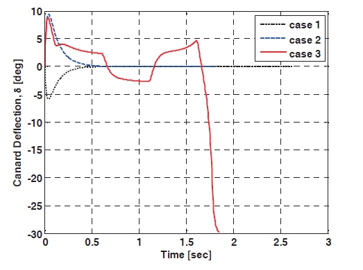
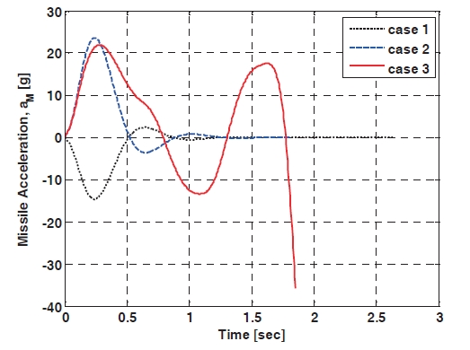
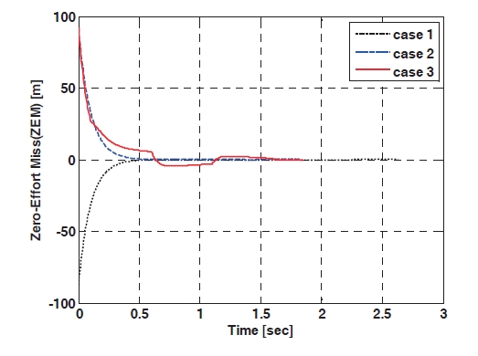
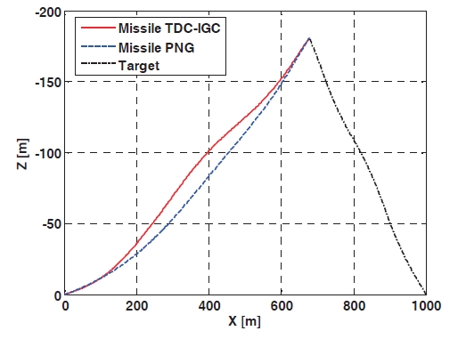
Figure 2 shows the engagement trajectories when the IGC controller using the TDC technique and the PNG are applied, respectively, and the target flies with a squarewave evasive maneuver. The miss-distance of the proposed IGC controller is 0.192 m, and the one of the PNG is 1.172 m, so the proposed algorithm shows better performance than the PNG. In addition, the miss-distance of the first and second case is 0.125 m, 0.102 m, respectively, so it is inferred from the results of the simulation that the IGC controller using TDC technique has a good performance. The canard deflection angles are shown in Fig. 3 The canard deflection of the first case is negative values, to hit the target located on the fixed position, because the target is stationary and the missile has a positive initial flight path angle. The canard deflection of the second case is positive values until about 0.5 sec, and then there is no canard deflection command because the missile enters the collision course and the ZEM is almost zero. The canard deflection of the third case changes continuously between positive values and negative values as the target flies with the evasive maneuver. Figure 4 shows the acceleration profiles and that more missile maneuver effort to hit the target is needed in case three. The ZEM is plotted in Fig. 5,and the initial ZEM can be increased as the initial
heading error is increased. As the time goes on, the ZEM is decreased in all cases, and the transient phase of the third case is worst because of the target evasive maneuver.
In this paper, the novel integrated missile guidance and control law using the TDC technique was proposed. The TDC law is a robust nonlinear control technique and has an advantage that can directly estimate the unknown dynamics and disturbance using one-step time delay. To design the IGC, the ZEM is used, and analytically deriving one is very complicated if the full nonlinear kinematics and dynamics is applied. Thus, the linearized kinematics and dynamics were derived to obtain the ZEM, but the derivative of the ZEM was determined from the nonlinear ones. The numerical simulation results show that the proposed IGC controller has small miss-distances regardless of the stationary target or moving target and better performance than the classical PNG. The performance of the proposed IGC using the TDC technique is affected by the sampling time of the controller,so if possible, the sampling time has to have a small value.
From these results, the TDC technique could be used to design the guidance law or the autopilot of the missile and the aircraft as well as the IGC controller.