Aerospace structures are usually designed as “passive”systems, i.e. their topology, geometry and material is defined during the development process in order to satisfy a set of different requirements with minimum weight. These design parameters are kept fixed during system operation. In recent years structures are considered where the actual structural behavior is observed via sensors, which then is improved via actuators triggered by control loops to achieve even better performance by adapting to actual environment and loads.These structures are called active or smart structures, the latter especially in cases where actuating or sensing smart materials such as piezo-electric materials are integrated.Examples of such adaptive or active structures are actively damped vibrations of aircraft wings or of helicopter rotors,or the shape control of high precision space reflectors. This concept is even further extended to massively adaptive or morphing structures with significant shape change in order to adapt to the actual mission status. Examples for this are shape morphing wings which adapt to the actual flight conditions to achieve high aerodynamic flight mechanics performance over a wide mission regime. In space structures, shape morphing communication antenna reflectors shall modify their shape to steer and focus reflected electromagnetic waves for regional concentration on earth´s surface to adapt to modified communication needs. For aircraft this leads to aero-elastic interaction, while in satellite reflectors proper radio frequency(RF) mechanics interaction is needed. Since it is the adaption or morphing of mainly the non-rigid body or structure that is relevant, mini-flaps or similar devices actuated more or less as rigid bodies are not considered in this paper.
Irrespective of whether one looks to active or shape morphing structures, the additional mass, volume, force amplitude and power needed by the actuation mechanisms significantly determines the overall benefit on the system level. This then leads to selecting proper materials, structure and actuation mechanisms to be synthesized in the active or morphing structure concept. While the active and morphing parts in aircraft have to take significant if not very high loads, those in satellites often have to work very precisely under severe environmental conditions, with external mechanical loads often being negligible in space operation.The technological readiness level (TRL) of active structures is more advanced than that of morphing structures, mainly because active structures often are (still) designed as a kind of add on to classical main structures. They are already partly used in applications such as active damping or dynamic load alleviation of aircraft wings or for shape control of precision space reflectors. Morphing structures need a more fundamental change in design concepts and approaches and are mostly still in the stage of laboratory models.
These questions and tasks are addressed in the following by discussing technological as well as design and simulation aspects. After a view on different examples and related materials, structural concepts, mechanisms and their syntheses, different simulation and design optimization approaches are addressed. This paper is considered as an overview of most aspects to be taken into account in this context, but is not considered to be a comprehensive literature review per se. Various representative papers are discussed for the different aspects, and where applicable this is merged with presentation of results from the authors activities.
2. Examples of Active Aerospace Structures
The concept and challenges of active or adaptive aerospace structures become obvious from several application examples as presented in this chapter. For aeronautical applications these examples are:
? Active vibration damping and dynamic load alleviation for aircraft wings
? Dynamic deformation control of helicopter rotors to improve their aerodynamic behavior and reduce their noise and vibration level
For spacecraft applications, these examples are:
? Active damping and dynamic load alleviation of launcher payloads
? Active damping of satellite solar array panels
? Shape control of precision shape reflectors
2.1 Active vibration damping and dynamic load alleviation for aircraft wings
The economy and comfort of modern aircraft can be significantly improved by actively using the control surfaces
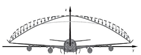
(spoilers, rudders) to influence the loads distribution and especially the dynamic part of these loads acting upon the wing. This is outlined in Fig. 1 the dotted line shows the stationary distribution of lift forces over wing length, while the hatched line is that resulting from an additional gust.Proper counter movements of control surfaces shall reduce this dynamic part resulting in a lift distribution given by the thick line, which reduces bending and fatigue effects close to the wing roots (Henrichfreise et al., 2003). In addition to this load alleviation, an additional benefit is the damping of wing vibrations in a frequency range that may be uncomfortable for the passenger.
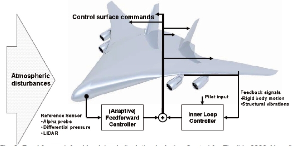
On the Airbus A330/A340 and the Boeing 777 feedback control drives the control surfaces (i.e. rudder, elevator,ailerons) using measured structural accelerations to reduce oscillations (Dornheim, 1998). The active vibration control design must be robust or adaptive against plant variations such as decreasing propellant levels during flight. Feedforward control can provide an improved vibration reduction compared to feedback control if a proper reference signal is available. A gust load alleviation system for the DLR, German Aerospace Center Advanced Technologies Testing Aircraft System (ATTAS) is presented by Hecker and Hahn (2007)with a feedback system for the control of the first symmetric vertical wing bending mode and an additional feed-forward controller for gust load alleviation. Alpha probes or Lidar provide the reference signal, where reduction in amplitudes in the order of 50% could be achieved.
These concepts are investigated further by simulations and wind tunnel investigations (Wildschek et al., 2006, 2007). In the European study Active Control for Flexible 2020 Aircraft,they are transferred to advanced aircraft configurations such as blended-wing-body (Fig.2 ). The definition of the aircraft configuration is described by Paulus et al. (2011), while related gust load alleviation is investigated by Wildsckek et al. (2010). Possible structural mass savings are currently investigated by comparing results obtained from structural optimization with and without dynamic load alleviation
systems. Structural optimization with a focus on gust loads effects is discussed by Petersson and Baier (2011).
Among different active aerospace structures concepts,active dynamic load alleviation on aircraft wings can be considered as one with relatively high TRL. A likely reason for this is the high gain which can be obtained with actuators that are already part of the wing.
2.2 Dynamic deformation control of helicopter rotors
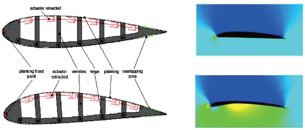
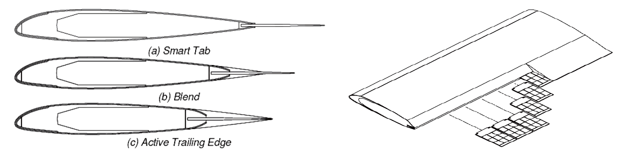
Today, helicopters still suffer from their environmental impact regarding external noise, fuel consumption and emissions, low passenger comfort (noise and vibrations) or limited range. A main sources of noise and vibrations is the main rotor, especially in fast forward and descent flight. The rotor blades also have to pass through turbulences generated by the blades in front, which enhances the negative effects.As such blade control systems shall reduce vibration, noise and power consumption. The most advanced approaches so far are the direct twist concept (Straub et al., 2004) and active trailing edge (ATE) flaps (Maucher et al., 2007), where induced dynamic pressure load variations generate bending and especially torsion deformations. The structure-fluidrotor interactions require intense investigation of the aeroelastic behavior (Lim and Lee, 2009). A helicopter equipped with trailing edge flaps was first flight tested by Eurocopter in 2005 on a BK117 helicopter (Roth et al., 2007), confirming the expected aerodynamic improvements including those in reduced noise and vibration levels.
Similar to trailing edge servo flaps with discrete hinges,continuous blade trailing edge deformation may be realized.The ATE is actuated by a multi-morph bender including piezoelectric ceramics, glass fiber reinforced plastics and further components (Maucher, 2011). Advantages of the ATE concept as outlined in Fig. 3 are its smoothly deflected airfoil contour, structurally integrated hinges, and mass savings compared to active flaps concepts.
2.3 Launcher payload vibration attenuation
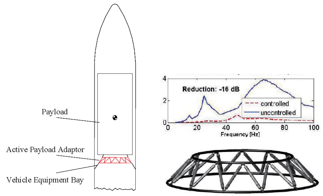
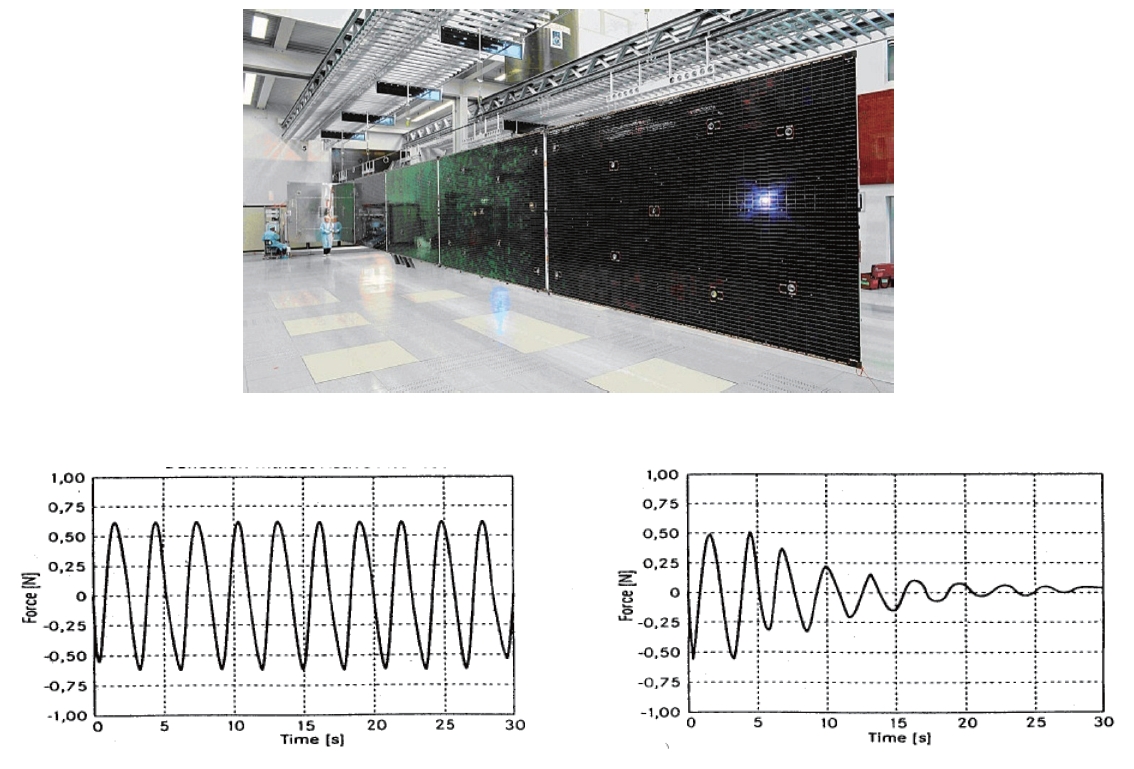
Launcher payloads as well as the launcher itself experience severe dynamic excitations during launch, coming from engines, pumps, aerodynamic forces and other sources. In order to reduce these loads especially on the payloads of satellites, launcher-payload interface trusses are investigated with integrated large piezo-electric stack actuators to attenuate such vibrations of the launcher payloads. The underlying concept is outlined in Fig. 4First results are quite promising, as can be seen from shock spectra shown in the upper right of this figure having been obtained from dynamic and control loop simulations without and with active attenuation (Rittweger et al., 2005). Further work on this concentrates on mass reduction for the electronic and power parts, as well as on increasing robustness and reliability.
2.4 Active damping of large satellite solar arrays
Active damping of often large solar array panels might be relevant during launch, but even more so in space. The reason for the first type is dynamic load reduction, while attenuation in orbit is aimed for disturbance rejection on the satellite platform due to vibrating arrays. This improves performance of (optical) instruments of the satellite, and also may reduce complexity of its attitude control system.Simulation results obtained from disturbance rejection by controlled linear piezo-electric actuators integrated into the interface structure between solar array and the satellite bus are given in Fig. 5. The simulation results have been confirmed by laboratory tests on simplified solar array dummies.
It should be noted that large deployed solar arrays might have first eigenfrequencies in the order of 0.1 Hz or even less, giving rise to challenging sensing and actuation technologies.
For attenuation of launch loads, a vibration controller based on an evaluation of the most important modes derived from finite element (FE) analysis of an experimental test model has been defined derived (Reinicke et al., 2010).
The controller is designed as a linear quadratic Gaussian controller using a static Kalman filter as the state estimator.Simulations show considerable attenuation of modal vibrations for the most relevant six modes below 120 Hz. A prototype model has been designed and manufactured for experimental testing. This panel features six piezoelectric patch actuators attached to its rear to control the most important regional mode shapes. Damping could be more
than doubled or tripled compared to that of the passive structure.
2.5 Precision reflector shape control
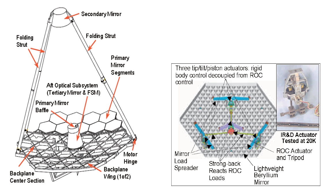
While the preceding examples are related to elastodynamics and vibration attenuation, shape control of highly precise space reflectors have to keep their actual shape deformed by quasi-static or low frequency disturbances such as different temperature loads as close as possible to the optically ideal shape (e.g. a parabolic surface). Since requirements on shape precision are often only fractions of ㎛ of shape deviations, actuator forces have to be introduced smoothly in order to avoid negative effects on shape accuracy. In addition, the shape control system and especially its actuator and load introduction mechanisms have to work under severe environmental conditions. This might be one reason why active shape control for space reflectors is far less advanced than that for reflectors of large ground telescopes. A practical example for space application is the shape control of the reflector on the James Webb telescope which is in its final stages of development. As can be seen from Fig. 6, it consists of many hexagon panels,each of which is controlled as a rigid body and in addition by elastic shape control. Actuation mechanisms which have to smoothly introduce control forces on the backside of the panels are shown in the right hand side of this figure together with actuators to be operated at 20 °K (Nella et al., 2009).
2.6 On simulation and optimization of active structures
Modeling structural dynamics via finite element methods(FEM) leads to the discrete equations of motion of an active structure:
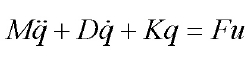
where M, D, and K denote the mass, damping, and stiffness matrices, respectively, and q is the degrees of freedom. The term Fu denotes the actuator influence on the structure, with u being the trigger quantity like piezo-electric voltages and F the transfer or influence matrix leading to forces. In case of aircraft wing damping for example, the matrices must also include aerodynamic effects.
These equations of motion are often transformed into state space equations, which in the case of displacements and velocities chosen as state variables lead to:
From this standard format of first order system of differential equations, control parameters are determined(Preumont, 2002). Transformation into modal space leads to a decoupling of the state differential equations.
As the number of degrees of freedom and the size of the matrices are often quite large and can easily be in the order of hundreds of thousands, model reduction techniques are to be applied. Since the access to structural design parameters then gets lost, a parameterized model of order reduction should be envisaged. This is briefly addressed in the following.
2.6.1 Model order reduction
Structural models obtained by using FEM are often too large for application in combination with control design tools. As such model reduction has to be undertaken. Since a modal representation is often used, a reduction is performed by selection of natural modes that lie in the frequency range of control, are strongly controllable and observable with the chosen actuator and sensor configuration, and substantially contribute to undesirable structural motion in case of disturbances.
These criteria may be expressed numerically using Hankel singular values or balanced gains if the system inputs and outputs are chosen appropriately. This method of “balanced reduction” can be applied mostly based on modal data which makes this method numerically fast and efficient.Methods based on Ritz and Krylov vector projections are advantageous to properly take into account quasi-static system behavior, but decoupling of the equations of motion is no longer feasible. An overview on model reduction methods can be found in Su and Craig (1991).
2.6.2 Parameterized reduced models
In case modifications of parameters of the active structure are to be undertaken during the design and simulation process,model reductions would have to be carried out repeatedly.Since the process of model reduction is computationally more costly than a single analysis with a full model, methods providing parameterized reduced models with explicit access to design parameters in the reduced model space are in order, see for example Antoulas and Sorensen (2001). The reduced model can then be used for parameter studies and design optimization for such (active) structures, possibly requiring an update of the parameterized reduced model only after larger parameter changes. Moment matching reduction methods determine a common projection space which contains parametric effects. Interpolation based methods approximate parametric effects after reduction.Lohmann and Eid [LE09] performed linear approximations with weighted functions.
An intensive discussion and further improvement of such techniques is given by Yoo (2010) and Yoo and Baier (2009)with applications in shape control and active damping simulations of space reflectors and solar arrays, respectively.Model reductions down to less than 1% of the original size have been carried out with parameterizations on material and geometrical structural properties. The simulation results in this case are still quite close to those of the original models, even for parameter changes in the order of 50%. In aircraft dynamic load alleviation studies, parameterization is in order to cover different flight conditions such as Mach numbers and varying propellant mass.
2.6.3 Actuator positioning
Put simply, the actuators should be positioned at areas of relatively high energy content compared to other areas. For strain inducing actuators this usually means areas of relatively high (modal) strain energy. For more or less laterally acting proof mass or also aerodynamic actuators these are areas of relatively high displacement or kinetic energy. This can be handled more strictly by measures of controllability, see also Preumont (2002).
In design optimization, position variables can also be considered as continuous parameters, being constrained for example, by geometric requirements such as avoiding
actuator overlapping or staying inside specified regions.Nevertheless, proper mapping of actuator forces onto the FEM degrees of freedoms has to be carried out during the optimization steps with varying positions. Most of the published work regarding optimal placement of piezoelectric actuator patches focuses on relatively simple structures such as beams or plates. Many of these papers assume that sensors are collocated with actuators. In large scale practical cases, actuator positioning is often determined by a mix of engineering insight, technical needs, and controllability measures also determined via actuator position sensitivity analysis.
3.1 Motivation and basic concepts
Aircraft wings are usually optimized for a specific design point, for example relevant Mach and Reynolds numbers,together with general system requirements such as flight distance, and payload. At this design point the wing reaches its best aerodynamic performance. With the change of these flight conditions, the efficiency of the wing decreases. A morphing wing shall adapt its shape or geometry in a certain range to achieve optimum behavior for a wider range of flight conditions.
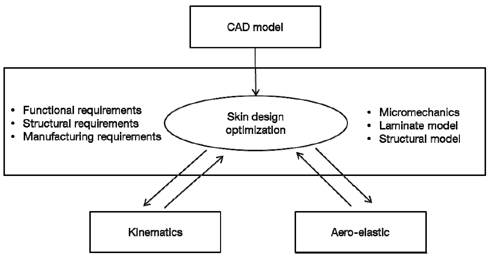
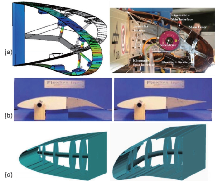
The basic technical principle gets obvious from the generic or abstract concept shown in Fig. 7,which also demonstrates the required synthesis of structure, actuation mechanisms and flexible skins. This also indicates that a proper balance between sufficient flexibility on the one side and high load carrying capability on the other has to be achieved.Wittmann et al. (2009) derived a framework for assessing the benefit of morphing parts on aircraft system level and identified priorities for such parts. Wittmann et al. (2010)show that morphing winglets are also interesting options,a point hardly addressed in literature (Ursache et al., 2007).Irrespective of the type of morphing parts, a relevant benefit can be achieved only if sufficiently low additional mass for example, morphing actuation mechanisms and structures are needed.
Most of the concepts investigated so far are related to morphing leading or trailing edges for unmanned aerial vehicles (Friswell and Inman, 2006) up to large civil aircraft.The latter have been mostly demonstrated in (scaled)laboratory models. The “smart droop nose concept” (Monner et al., 2009) uses a hybrid skin consisting of glass fiber and carbon fiber layers being strained typically up to around 1% in its demonstration model. For a morphing leading edge with eccentric beam actuation mechanism a 2-3 mm aluminum alloy and fiber composite skin were investigated, among others. Referring to Love et al. (2004), a skin made out of 12 layers of glass fiber/epoxy (GF) with a symmetrical laminate [+-45/03/90]s and 3 mm thickness requires actuation forces under aerodynamic loads in the order of 10 KN and higher to achieve a defined leading edge deflection. The percentage of such forces for morphing vs. carrying loads depends on the design concept, type of materials, kinematics and actuatorskin interaction as well as boundary conditions. In general,high levels of required actuation energy and force amplitudes will increase system complexity required additional mass and limit the choice of actuator types.
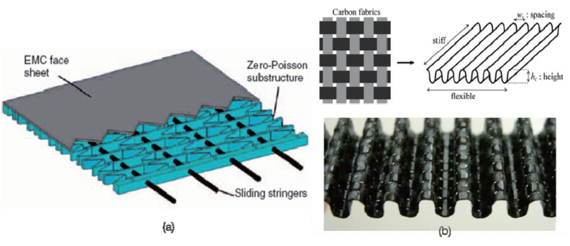
The skins of morphing wings are a challenging design element, since they have to be quite flexible or deformable and at the same time have to take and transfer high aerodynamic loads. As such the skin should have an orthogonal behavior with stiff parts in the direction of wing span and flexible(polymeric?) parts in the other. Thill et al. (2008) extensively reviewed technologies and concepts of morphing skins, such as properly tailored laminates or structural non-isotropy achieved geometrically for example by corrugation, see also Fig. .9 A sandwich morphing skin consists of flexible elastomers as cover and different types of cores including auxetic materials, see also Thill et al. (2008). This would allow relatively low in-plane stiffness of the skin combined with sufficiently high bending stiffness. One promising skin polymer tested was found to be a thermoplastic polyurethane.A suggestion was made to combine a woven material with a polyurethane like, that way the high strength required would be achieved by the fibers and the elasticity by the polymer. As discussed in a later chapter, a similar approach is taken for designing a morphing skin for a space reflector. Inflatable or fabric skins seem to be suitable for lower Reynold numbers being an integral part of an actuation system (Kirn et al.,2011).
“Flexibility” may also be achieved with relatively small strain by proper rim or boundary conditions, or with sufficiently low stresses even under higher strain by nonlinear material behavior via flexible matrix materials or special fiber arrangements by proper weaving/braiding techniques.Multi-stable skins and those including advanced smart actuators such as shape memory materials are also discussed.Such concepts are still at low technical maturity levels and do not seem to be suitable for nearer term applications. In regard to their potential to satisfy the total set of functional,strength, manufacturing and certification requirements,properly tailored composites skins are considered as most promising.
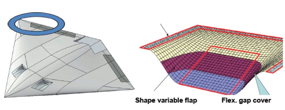
An R&D Project “Sagitta” (Fig.10 ) has been initialized by European Aeronautic Defence and Space (EADS) Cassidian in Germany involving several universities and research institutes. Envisaged advanced technologies for example in configuration or communication and flight control concepts also include morphing flaps and gap covers to improve agility and further reduce radar signature.
3.3 On the interaction of structure-skin-mechanism
In the previous example of morphing droop nose actuation is carried out via lever mechanisms. Actuation loads are introduced to the skin at its lateral stiffeners. These skin stiffeners avoid buckling under aerodynamic loads and at the same time smoothly distribute the actuation loads to avoid undesirable curvature changes of the skin.
In contrast to conventional actuation mechanisms,compliant structures combine load carrying and actuation functions. For example, the mission adaptive compliant wing (MACW) was developed using sophisticated
algorithms to design the topology and shape of an internal compliant structure (Kota et al., 2009), where design details are not discussed further. The MACW prototype system was successfully flight-tested using the Scaled Composite’s White Knight aircraft.
In principle, a compliant structure deforms smoothly as a whole and avoids high-stress concentrations. This design paradigm of distributed compliance offers additional benefits since the entire adaptive structure is viewed as a compliant mechanism that can move into complex predetermined positions with minimal force and can be locked in place at any desired configuration (Hasse and Campanile, 2009; Lu and Kota, 2003). While these structures have been described as“flexible,” they are to be designed also to resist deflection and stresses under significant external aerodynamic loading and are supposed to be just as stiff and strong as a conventional flap. The hingeless nature of compliant structure mechanism eliminates the backlash error and effectively reduces the production and maintenance costs associated with the multiple piece assembly. In case a proper design trade off between compliant structure actuation mechanism and load carrying capability can be found, mass penalties for morphing wings are then supposed to be low, which is
recommended to be a major design goal. So far not so many design details can be found in literature being substantiated at the aircraft level, which is possibly due to the difficulty of achieving good compromises between flexibility and load carrying capability.
Kagome structures are a concept that also deserves further investigations. They are statically determinate yet stiff, see Fig. 11 and Hutchinson et al. (2003).They can be actuated into relatively intricate surface shapes. The structure consists of a face sheet or skin with a Kagome activated backplane truss. Integrating linear actuators into various truss elements enables the shape of the solid face to be changed.Such a system aims to provide a solution to the problem of structural morphing by the removal of structural resistance to deformation. Of course the actuators then might have to take considerable load, and the implementation of pin joints could be difficult.
Previous investigations assumed the presence of a prefect skin material; that is a material able to transfer aerodynamic forces to the structure whilst accommodating large shape changes. Such skins are the subject of intense research, as outlined in this paper.
4. Shape Morphing Space Reflectors
While in satellite reflector shape control the design goal lies in keeping the shape a kind of fixed and as precise as possible under disturbances, shape morphing reflectors are to be used for redefining the behavior during the satellite’s mission in space. In certain cases this might be achievable via mild changes in the reflector shell’s curvature or focus,while in other cases drastic shape morphing is needed with high morphing amplitudes and high spatial frequency.
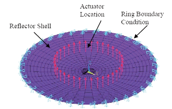
4.1 A mildly shape morphing reflector
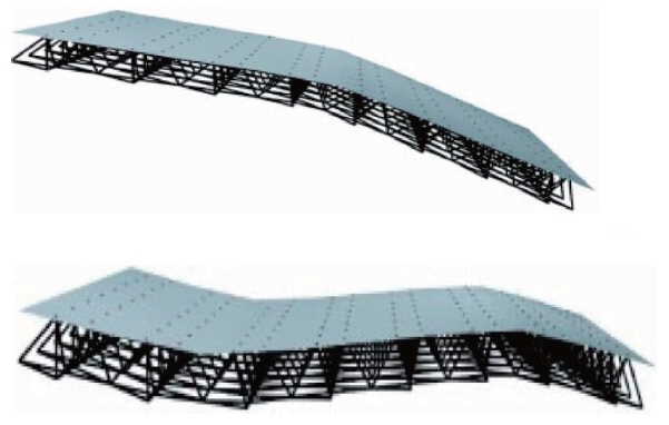
An example of a mildly morphing structure is a parabolic reflector that has to be morphed for moderate focus change by actuators attached to a ring structures integrated at the backside of the reflector (Fig.12 ). After this refocusing or change of (parabolic) curvature, the root mean square (RMS)error between actually morphed shape and ideal shape should be at a minimum. Design parameters to achieve this in the related design optimization problem are the number and positions of the actuators but also the radial thickness or stiffness distribution of the parabolic shell. For variable thickness distribution, the achieved shape accuracy after morphing gets much higher than in the case of constant shell thickness. For example, in a case of eight different properly determined shell thicknesses in radial direction,after focus modification the new shape’s RMS deviation from the ideal shape is four times less than in the case of constant shell thickness. This again shows the high interaction of the structural design with its actuating and morphing parts.
4.2 A massively shape morphing reflector
Some future communication satellites may require drastic yet precise shape reconfiguration or shape morphing during their operation in order to adapt for changing mission needs arising from changing communication data density or the redirection of radiating beams between different regions of the earth. As such shape modifications may require relatively high spatial frequencies and amplitudes possibly up to the cm-range with high precision, challenging requirements exist for such surfaces to be morphed as well as their actuation mechanisms.
4.2.1 Design concepts and RF-reflective skin material
The overall design and analysis approach consists of several steps. First, goal shapes are derived from electromagnetic analyses. Simulations for the actuated structure and skin allow a preliminary specification of their stiffness properties, where proper materials are then derived from meso-mechanical skin material models. Achieved data and properties are homogenized and introduced into an updated reflector structure model together with actuators. Parameter studies and design optimization techniques help to refine the properties. This also includes actuator positioning and determination of required strokes to achieve the goal shapes as accurately as possible while satisfying further functional and structural constraints. Simulation results and those from a laboratory model are outlined in Fig. 13.
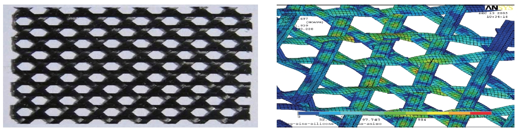
A new type of material consisting of carbon fiber reinforced silicone (CFRS) originally developed for large deployable reflectors (Datashvili et.al., 2011) is of high interest for morphing reflectors as well, see also Fig. 14 It consist of triaxially (0°, +/-60°) woven carbon fiber fabrics covered by a silicone resin system having a Tg at around-120°C. Above this temperature, the composite material is quite flexible for stowage and morphing but also stiff enough to achieve double curved reflecting surfaces in orbit. It has very low thermal expansion, and no micro-cracks have been observed for many temperature cycles between +/-150°C.
[Fig. 14.] Triaxially carbon fiber reinforced silicone and its meso-mechanical finite element model.
Electro-magnetic functionality has been proven as well. A detailed presentation of this material and related analysis and test results are discussed by Datashvili and Baier (2011)and Datashvili et al. (2011).
Low shear modulus is very important, since it results in lower required actuator forces, while moderate bending stiffness results in morphed shapes with smooth curvature change. Statically over-determinate fixation of the reflecting surface to the actuators has to be avoided. Further, a rotation-free interface design is needed. The free surface boundary of the reflector has been shown in Baier et al.(2009) to satisfactorily fulfill the shape-morphing surface requirements.
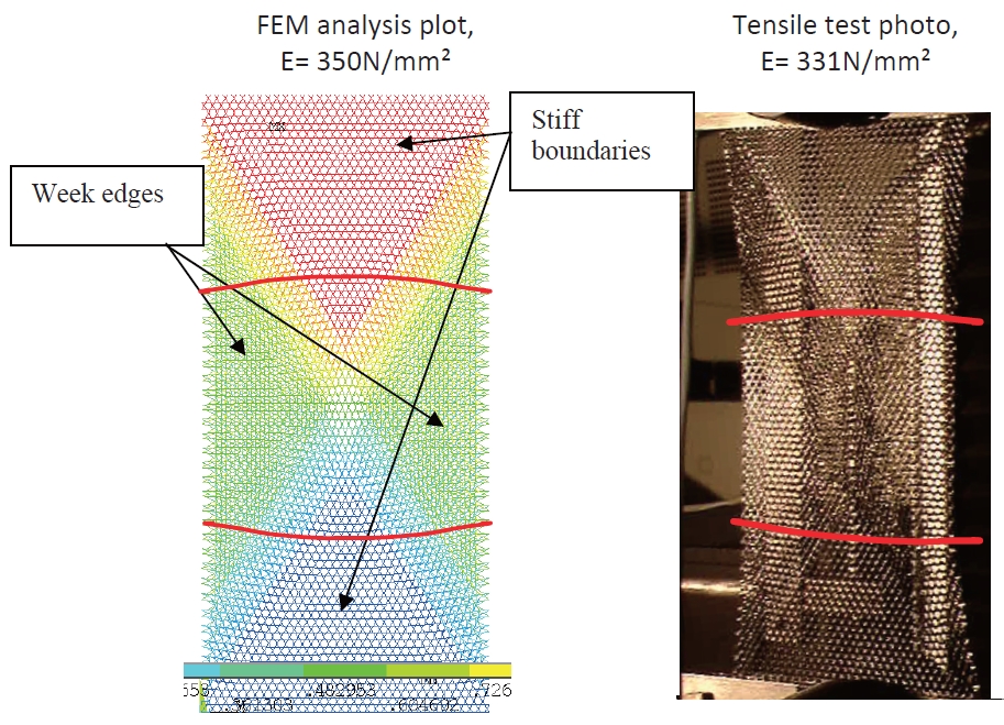
Tow geometry has to be covered in the meso-mechanical simulation models, which can be best achieved by solid FEs.This then leads to good correlation to sample test results (Fig.15). As a result of the high influence of free edge effects, the sample’s width has to be relatively large compared to that of classical test specimen.
In addition, due to the flexibility of the materials and difficulty to mount standard strain gauges, standard measurement methods cannot be used. Therefore contact free optical methods for strain measurement during load testing and alternative methods for coefficients of thermal expansion measurements have been developed and applied.
4.2.2 Skin-actuator interaction
Since this skin design requires actuator forces not exceeding the range of +/- 20 N, micro-actuators can be applied. With a mass of typically less than 50 grams they can provide displacement strokes of up to 25 mm, with achievable force amplitudes limited to approximately +/- 50 N. The possible use of such micro-actuators with low mass
and volume is important because required actuators density might reach around 50 per square meter, depending on the complexity of the goal shapes to be achieved.
Complementary to results from Washington et al. (2002),the positioning of the actuators is set to be quite regular as there is no real position preference to be expected for the very different sets of goal shapes. The displacement strokes needed to achieve the goal shapes as accurate as possible even for a high number of actuators are obtained from solving a least squares error problem between actual surface deformations or shapes generated by these strokes and the goal shapes,with technical limits of the actuator stroke amplitudes set as constrains (Baier et al. 2009). Coupled electric-mechanical approaches currently under investigation reveal even better results for the final antenna performance possibly with less actuators than those obtained from the decomposed or hierarchical approach of defining goal shapes from electric analysis first and then trying to achieve these by proper mechanical design.
Tests also reveal the importance of precise actuator alignment to be orthogonal to the surface around the actuator attachment areas. Smooth actuator load introduction is achieved by slightly higher skin thicknesses around the actuator hinge interface to the reflecting skin. These thicknesses smoothly decrease to nominal thicknesses in the“undisturbed” or actuator-free ranges.
4.2.3 Analysis-test correlation on reflector level
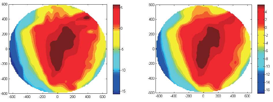
A geometrically scaled breadboard of reconfigurable reflectors was built for the purposes of validating the FE model and verifying the design concept. The reflective surface is made out of two continuous CFRS layers and patches on the back side around the actuator connection points to provide smooth actuator load introduction. The deformed shapes were measured by photogrammetry and compared to the simulated shape. The overall RMS shape difference between simulation and test is less than 0.2 mm. Similar results with a good matching of achieved actual shapes compared to specified goal shapes are obtained as shown in Fig. 16 with morphing amplitudes between -15 mm and +5 mm over a reflector diameter of 1.2 m, see also Datashvili and Baier (2011) and Datashvili et al. (2011). The tests also revealed several relevant details for example with respect to the alignment of actuators. Also special measurement techniques have been applied to cover the behavior over the full range of shape morphing, which relates to deformations,strains and also actuator force levels.
On Simulation and Optimization of Morphing Structures When it comes to simulation and optimization of shape morphing structures further things come into play and have to be taken into account compared to active structures. These are geometrical nonlinearities due to large displacements with mostly still relatively small strains, a possibly needed update of environmental loads for different morphed positions,and generally a strong interaction between materials,structures and actuation mechanisms and the related modeling and simulation approaches. On the other side,since the shape morphing process per se is often relatively slow compared to structural and parts vibration cycle times,vibration analysis can be handled by simplified means, if not neglected at all. Moreover, it has been often observed that though displacements are large but strains have to be limited, at least step-wise linearization can be applied with still reasonable results. The set of different methods and tools to be considered is outlined in Fig. 17,where aero-elastic simulations provide a link to the aerodynamic behavior for morphing wings, while for morphing reflectors these then are RF- and radiation pattern simulations.
The formulation of equations of motion in nonlinear FEM tools including the contributions of the kinematic constraints,elastic, plastic, damping or friction in the internal forces allows the combination of static, kinematic or dynamic
analysis. Motion simulation offers the numerical simulation of plane or 3D flexible articulated systems with different kind of kinematical joints. Often strong non-isotropy of the structures and its material has to be taken into account.
The definition of the material type of the morphing structure´s skin is part of the design and simulation task as well. The simulation is handled in a decomposed or hierarchical way, as outlined in Fig. 17 Starting with a first“reasonable” definition of the material and skin, structure and structure mechanism interaction analysis helps to more precisely specify required materials properties. These are to be achieved by materials design and simulation based on meso-mechanical material models. These then are homogenized to be fed into the structural models again. This likely needs several iterations to cover the interactions of skin materials, structure and mechanisms. In the longer term it might be expected that such a hierarchical and decomposed approach is substituted by simultaneous and multi-scale simulations ranging from material models to structuralmechanism interaction models.
Significant parts of the design problems can be stated as (mathematical) design optimization problems which complement and support the design process. Design goals can minimum morphing actuation energy and/or minimum deviations from defined goal shapes. Constraints to be observed are those on strength, stiffness (deformation,stability), limited shape deviations (or actuation energy),mass limits etc. Design or optimization variables may be layer thicknesses, fiber reinforcement angles, core height in case of thin sandwich concepts, or design parameters of actuation load distribution areas.
Mathematical optimization algorithms (especially the sequential quadratic programming [SQP] method) and evolutionary (EA)/genetic algorithms (GA) are used to solve such design optimization problems. While GA are quite generally applicable e.g. also including discrete design variables, SQP type mathematical optimization techniques usually achieve results in significantly less iteration steps in case of continuous design variables and availability of(numerical) gradients of object and constraint functions with respect to design variables. Some authors also use combined approaches between GA and SQP. Huber et al.(2010) significantly improved the convergence behavior of GA by using data mining techniques to identify successful patterns in the design parameter change processes of GA and to use these more often than random changes generated by standard GA.
As outlined above for the morphing space reflector skin,structural optimization is carried out to determine proper layer thicknesses and actuator strokes. For a given reflector and skin structure, optimal strokes of the often many(micro-)actuators are determined by solving least squares optimization problems, where the RMS deviations between generated achieved shapes and goal shapes are minimized while satisfying constraints for example on stroke amplitudes.First results from more integrated approaches with direct and simultaneous consideration of electro-magnetic behavior(instead of goal shapes) indicate that further improvements can be obtained even with a smaller number of actuators.
The level of interaction between skin materials, morphing structure and mechanisms also determines the extent of coupled structure-mechanism simulation and the related design optimization approach. Some authors argue for a clear distinction between the morphing/load carrying structure and the actuation mechanism, which allows a hierarchical simulation approach. Others argue for a higher integration between structure and mechanism by design,which then calls for a coupled approach. It can be expected that a higher synthesis between structure and mechanisms such as in the compliant structures mentioned above is also beneficial with respect to overall mass. When it comes to design optimization of such systems, related modeling and simulation approaches such as those presented by Lu and Kota (2003) are to be combined with optimization algorithms.Optimization techniques originally carried out for structural topology optimization could be favorably applied also within this context to determine the topology of the compliant structure (Santer and Pellegrino, 2009; Zakhama et al., 2009).But possibly there is no absolute truth about hierarchical vs.synthesized treatment. On one side a synthesized treatment might lead to even better results, while on the other side a hierarchical treatment can be better handled from a process and modeling and computational effort point of view.More experience has to be gained with more benchmark examples where possible benefits of synthesized treatment vs. hierarchical treatment are to be identified.
The examples in active and morphing structures indicate their benefit especially when proper actuation techniques lead to low penalties in mass, volume and power. This often requires proper synthesis between materials, structures and actuation mechanisms. Especially for morphing structures,still more experience has to be gained from different benchmark and demonstrator examples to identify best approaches, to increase their TRL and to identify achievable benefits at a system level. Compliant structures look quite promising, though more detailed large scale design concepts satisfying the basic requirements together with morphing skins are still to be investigated. This especially holds for aircraft wings with their kind of contradictory requirements on flexibility and load carrying capability. The investigations have to be based on simulation and design optimization techniques applied to innovative ideas.