Helicopters are inherently associated with the occurrence of vibration and noise as a result of the various aerodynamic phenomena occurring on the rotor. These are most pronounced in forward flight, in descent or the combination of the two flight regimes. In forward flight, advancing blades can experience an effective free stream velocity close to the speed of sound, thus developing transonic phenomena and shock waves for short periods of time. At the same time, the retreating blades can develop dynamic stall or eventually stall flutter. Both these phenomena lead to significant vibration on the rotor, which then transfers to the fuselage via the main shaft and the control system. In addition to this, all blades generate a helical tip vortex, which interaction with the other blades (called blade vortex interaction or “BVI”), the tail rotor or the fuselage leads again to vibration as well as to the characteristic slapping noise of helicopters.
The amplitude of vibration measured inside the fuselage of a helicopter is typically in the range of 0.4 g’s. In contrast,vibrations inside a fixed-wing aircraft are below 0.05 g’s (Konstanzer et al., 2008). This is what the rotorcraft community refers to as “jet-smooth ride.” The frequency of peak vibration is between 1/rev-N/rev (where N represents the number of blades), which typically corresponds to 2-8 Hz frequency depending on the size of the helicopter (Vallejo et al., 1998). Unfortunately, the resonance frequency of a human’s upper body is at around 5 Hz (Vallejo et al., 1998),i.e. in the middle of this range. It is therefore crucial to either move the vibration frequency away from this value or to reduce the magnitude of vibratory loads transferred to the pilot and the passengers.
Beside the negative effects on pilot health, vibration also limits the performance of a helicopter. Maximum forward flight speed is typically limited by the appearance of excessive vibrations in the control system?especially in the pitch link?rather than by reaching the maximum power of the propulsion unit (Stepniewski and Keys, 1984).
Thus, control of vibration on helicopters is important since it could lead to several advantages simultaneously:1) pilot service life can be extended, 2) forward flight performance could be improved, 3) pilot/passenger comfort can be improved (by getting closer to a “jet-smooth” ride),4) component weight could be reduced (since components would now be exposed to less fatigue loading), 5) component life can be extended, and thus 6) the overall operational costs of the helicopter could be reduced.
Helicopter noise also occurs as a consequence of the rotor aerodynamics and typically reaches about 80-120 dB in the far-field (Schlegel et al., 1996). This adds up from BVI noise,swishing noise and rotational noise. The first one is the result of the aerodynamic interference of the helical trip vortices with the other blades or the tail rotor. This is the main source of the characteristic “slapping” noise on helicopters. Swishing noise, on the other hand is a broadband noise generated by the random fluctuation of blade lift due to vortex shedding from either the blade ahead, fluctuations in the freestream velocity or from flow separation. The third component of noise, rotational noise is generated by the periodic force applied to the air, such as lift and drag along the azimuth of the rotor disk. Rotational noise can also lead to acoustic fatigue and vibration of the helicopter structure. The total
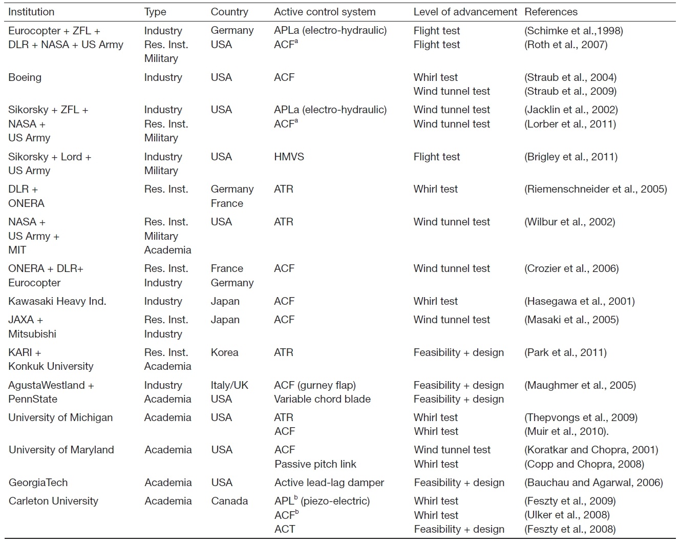
[Table 1.] Overview of worldwide research on rotor-based active control systems

Overview of worldwide research on rotor-based active control systems
noise level of a helicopter prohibits communications inside the cabin without headsets, whereas noise pollution is also very significant: a person standing on the ground will hear the characteristic “slapping” noise of a helicopter well before the helicopter is sighted. Also note that the sources of noise and vibration are often the same (such as BVI), thus the occurrence of these two phenomena is strongly coupled.
For these reasons, the development of vibration and noise reduction systems for helicopters have received considerable attention in the past two decades and is probably one of the most vivid research areas nowadays (Anusonti-Inthra and Gandhi, 2000, 2001; Bauchau and Agarwal, 2006; Brigley et al., 2011; Copp and Chopra, 2008; Crozier et al., 2006; Feszty et al., 2008, 2009; Gerontakos and Lee, 2007; Hasegawa et al.,2001; Jacklin et al., 2002; Khoshlahjeh et al., 2011; Kloeppel and Enenkl, 2005; Koratkar and Chopra, 2001; Lorber et al.,2011; Masaki et al., 2005; Maughmer et al., 2005; Muir et al.,2010; Nitzsche and Breitbach, 1994; Nitzsche et al., 1993; Park et al., 2011; Riemenschneider et al., 2005; Roth et al., 2007;Schimke et al., 1998; Straub et al., 2004, 2009; Thepvongs et al., 2009; Ulker et al., 2008; Wall et al., 2008; Wilbur et al.,2002; Woods et al., 2011).
Vibration and noise can be controlled either via passive or active control systems. Passive control systems, which are currently the industry standard, are able to tackle either noise or vibration at specific flight regimes only. They are usually based on the principle of a mass-spring-damper system. Their advantage is their simplicity, while the main disadvantage is that they can only be tailored to one specific flight regime (e.g. for forward flight at a specific speed) but not for other flight speeds or for climb or descent. Therefore,a passive device is only useful for a very narrow window from the full operational envelope and might compromise the performance of the vehicle in other flight regimes.
This gave the impetus for the industry to develop active control systems, which can adaptively change the control parameters depending on the flight regime. Thus, active control systems promise close-to-optimum control of the undesired phenomenon for the entire operational envelope of the helicopter. They can be either of fuselage-based or rotor-based type. In a fuselage-based system, typically a smart material actuator is resonated at a certain adjustable frequency to counteract cabin vibrations. Although such system can be very efficient in reducing vibration, rotorbased systems are viewed to be more superior since they can tackle vibration and noise at their source?on the rotor blade itself.
Table 1 provides an overview of the ongoing research of rotor-based active control systems worldwide and the level of development they have reached. Note that the development level is represented by the chain of “feasibility study?system design?whirl test?wind tunnel test?flight test,” i.e. the closer a group is to flight testing, the more mature their technology is. Also note that only those technologies have been listed,which allow to control blades individually, i.e. higher harmonic control research has been omitted from this review. The exception is Sikorsky and Lord’s hub mounted vibration supression system (HMVS) (Brigley et al., 2011),which does not appear to allow individual blade control, but is the first rotor-based active control system mass-produced and in operation nowadays.
It can be seen from Table 1 that there are basically four types of rotor-based active control technologies: 1) the actively controlled flap (ACF), 2) active twist rotor (ATR), 3)actively controlled tip (ACT) and 4) active pitch link (APL).From these, the first three can be classified as blade-based devices, while the last one as hub-based device. A hub based device is often viewed more advantageous since it can leave the most delicate piece of the rotor?the blade?intact,i.e. unchanged from the proven conventional design. One can also notice that the most popular and most advanced technology is the ACF. This is pursued by nearly a dozen research groups worldwide and is the only blade-based active control technology flight tested so far (by Eurocopter in 2005[Roth et al., 2007]). The ACF in general can be optimized to reduce either vibration or noise, but usually at the expense of the other (Straub et al., 2009). ATR can essentially achieve the same effect as the ACF, but with much higher voltage and power consumption. Their advantage is that they do not have moving components and hence they are expected to operate more reliably in harsh environments, such as dust, snow, etc.The ACT system aims to alter the anhedral angle of the blade tip. This is a quasi-steady system, i.e. it is activated by the pilot before entering a certain flight regime. It promises to reduce BVI noise and vibration by displacing the helical tip vortex and thus controlling the most critical parameter of this undesired phenomenon: the so-called “BVI miss-distance”.This represents the distance between the blade and the tip vortex. Lastly, the APL technology allows to change the length of each blade’s pitch link individually, thus changing the blade pitch angle and the blade aerodynamic loads. This system showed great reduction of vibration or noise in a hydraulically driven system. However, a hydraulic system is viewed to be unsuitable for mass production helicopters due to weight and reliability issues. Thus, the need for developing an electrically driven system was formulated about a decade ago (Kloeppel and Enenkl, 2005). However, the power density of electrical drive is much less than that of hydraulic drive (Woods et al., 2011), and therefore, no constructing an electrically driven APL remains a challenge.
In Canada, the research of rotor-based actively controlled systems is concentrated mostly in Ottawa, Ontario, where Carleton University’s Rotorcraft Research Group, the National Research Council of Canada (NRC) as well as a local company called Smart Rotor Systems Inc. has formed an innovation triangle to explore new frontiers in this field. They collaborate in the research, development and demonstration of a novel “hybrid control” concept, which unique feature is the simultaneous application of multiple active control systems on a single blade (Feszty et al., 2008,2009). The primary purpose of employing multiple systems is to reduce vibration and noise simultaneously as well as to improve the efficiency of blade-based active control systems.This research has involved about 30 researchers (professors,postdoctoral researchers, graduate students, engineers) in the past 8 years and generated more than two dozen scientific publications. The aim of this review paper is to provide an overview of the history as well as the latest achievements of this innovation triangle.
Beside this group, there have been other examples of research on rotor-based active control systems in Canada.Carleton University and the NRC has collaborated on using ATR for mitigating the negative effects of “blade sailing,” a phenomenon occurring in ship-helicopter interaction (Wall et al., 2008). They performed scaled whirl tower as well as wind tunnel tests in 2008 and 2009. Also, McGill University in Montreal has conducted an extensive two-dimensional(2D) wind tunnel test campaign to explore the capabilities of ACF for mitigating dynamic stall induced vibrations on the retreating blades (Gerontakos and Lee, 2007).
The present paper provides an overview of the research of the Ottawa-based innovation triangle, i.e. that consisting of Carleton University?NRC?Smart Rotor Systems Inc. It will first describe the basic idea of the unique “hybrid control”concept. This will be followed by a review of the smart hybrid active rotor control (SHARCS) research project, which is the framework for demonstrating the hybrid control concept experimentally. Next, the computational and experimental tools used for the SHARCS project are described. Finally, the three rotor-based actively controlled systems of the SHARCS project, i.e. the ACT, the ACF and the APL will be reviewed.
The major advantage of any actively controlled system is its adaptability, i.e. its ability to control vibration (or noise) at various flight regimes. This is accomplished by adaptively changing the actuation schedule as the flight regime changes. For example Kloeppel and Enenkl (2005),has shown for a 4-bladed rotor that 2/rev frequency should be applied to reduce BVI vibrations, whereas 3/rev-5/rev frequency to reduce cabin vibrations and 1/rev frequency to reduce vibrations due to rotor imbalance. Similarly, 2/rev frequency should be used to reduce BVI noise, whereas 5/rev-6/rev frequency would be desired to reduce shock wave noise (Kloeppel and Enenkl, 2005). It is clear from these data,that with one single system (such as the ACF), one cannot control two phenomena at the same time. For example,cabin vibrations and BVI noise could not be reduced at the same time. What worse: in many cases not just that one cannot control two phenomena at the same time, but when one phenomena is reduced, the other becomes deteriorated,e.g. when vibration is reduced, noise increases up and vice versa (Roth et al., 2007; Straub et al., 2009). This could seriously question the value of adding a control system to a helicopter.
The hybrid control concept proposed by the authors(Feszty et al., 2009) aims to address this shortcoming. It builds on that theorem of control theory that in order to meet two control objectives one needs to employ two independent control systems. Therefore, the basic idea of “hybrid control”is to use two or more independent control systems on a single rotor blade. Thus, when one is optimized to reduce vibration, the other one can be optimized to reduce noise or yet another mode of vibration (such as cabin vibration or rotor imbalance). Thus, the hybrid control concept promises to achieve simultaneous reduction of vibration and noise.
A specific aspect of the hybrid control concept proposed by the authors is that it is based on combining not just two flow control systems (i.e. any two of the ACF, ATR, ACT) but a flow control and a structural control system.
Structural control really means “stiffness control” of the blade root. This concept was first conceived by Nitzsche in 1993 (Nitzsche and Breitbach, 1994; Nitzsche et al., 1993)and independently confirmed by Gandhi in 1999 (Anusonti-Inthra and Gandhi, 2000, 2001). They both have shown via theoretical and numerical analysis that that cyclic variation of blade root stiffness can lead to significant reduction of vibration. The question was: can anyone design and build a technology enabling stiffness control?
The answer came in 1999, when Nitzsche proposed and patented the concept of a generic stiffness control device called “Smart Spring” (Nitzsche, 1996; Nitzsche et al., 2005b).A smart spring involves a set of springs, friction surfaces and piezoelectric actuators. It can change the resultant stiffness of the system between two stiffness values, depending on the control voltage applied to the actuators. More detailed description of the Smart Spring concept will be provided later in the paper.
Thus, the hybrid control concept proposed by Nitzsche and Feszty and filed for patent in 2008 (Nitzsche and Feszty,2008) is based on combining a flow control system with a stiffness control system, with the latter one embodying the smart spring concept.
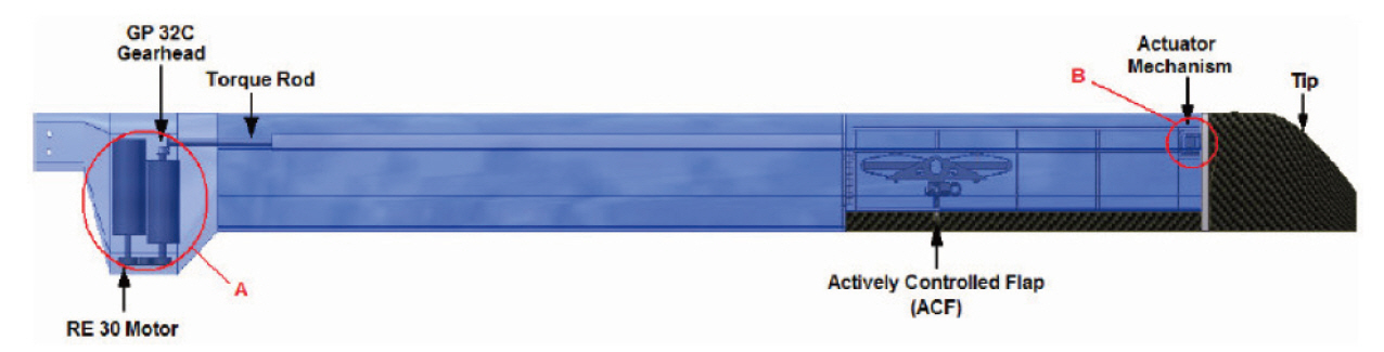
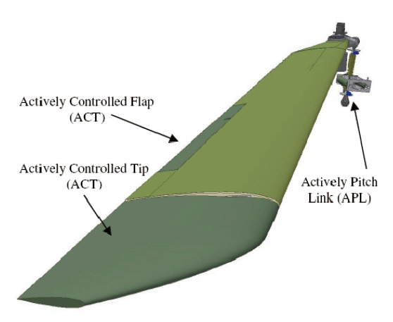
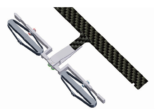
In 2004, a project called SHARCS has been launched at Carleton University by Feszty and Nitzsche, which aims to demonstrate experimentally that hybrid control can indeed reduce vibration and noise simultaneously (Nitzsche et al.,2005a). For this project, the ambitious goal of including three independent control systems per blade has been proposed(Fig. 1). From the three systems, two are blade-based flow control systems (the ACT and the ACF) whereas the third one is a hub-based stiffness control system. This latter one is in fact a smart spring replacing the conventional pitch link.
The ACT acts as a static controller and should reduce BVI noise by displacing the tip vortex to lower vertical location.The basic idea of this technology would be to displace the blade tip vortex, thus increasing the BVI miss distance and promising to reduce BVI induced noise and vibration. The ACT spans between 90%-100% of the radius and should be able to deflect to 20 deg down within 30 seconds, i.e. it would be manually activated by the pilot before entering a “noisy”flight regime, such as low speed descent.
The ACF should reduce vibration and/or noise and it was defined to span between 65%-85% radius of the blade with a 15% relative chord length. This location proved to be the best trade-off between aerodynamic efficiency and actuation power based on Kloeppel and Enenkl (2005). The ACF should enable a flap deflection range of 4 degrees (current
state-of-the-art deflections are around ±2 deg [Straub et al.,2009]) at (N+1)/rev frequency, where N is the number of blades. Note that the ACF could reduce either vibration or noise, depending on the actuation schedule imposed.
Finally, the APL is a blade stiffness control system based on the smart spring concept, which shall enable the highfrequency(again, as high as (N+1)/rev) variation of the blade stiffness to reduce either vibration or noise, depending on the actuation schedule. Note, that the APL replaces the conventional pitch link and is external to the blade itself, i.e.not affecting the blade structural design in itself.
From organizational point of view, the SHARCS project has been an international collaboration lead by Carleton University. All design integration, construction and testing is conducted by Carleton University, whereas the main collaborators over the history of the project included AgustaWestland, who supported the launch of this project,German Aerospace Centre (DLR) Braunschweig from Germany, who provided facilities and expertise for the first wave of whirl tower tests (Feszty et al., 2009; Ulker et al., 2008), University of Rome La Sapienza, Italy, who contributed with expertise in the modal analysis of the rotor system (Coppotelli et al., 2008; Feszty et al., 2009; Nitzsche et al., 2005a), University of Rome Three, Italy, who conducted computational feasibility studies on the hybrid control concept (Feszty et al., 2009; Gennaretti et al., 2003), the National Technical University of Athens in Greece, who was driving the development of computational aeroelastic tools for feasibility studies (Feszty et al., 2009; Oxley, 2009; Oxley et al., 2009; Ulker, 2011) and the Technical University of Munich,who provided expertise in developing computational models for the scaled composite blades (Khomutov, 2010). Most recently, two major partners from Ottawa have joined the project, the NRC, who provided facilities to host the newly built Carleton Whirl Tower facility, and Smart Rotor Systems Inc., who drives the commercialization and engineering development of the system.
In order to design a rotor with three actively controlled systems and to assess its feasibility for reducing vibration and noise, one needs a 3D fully aeroelastic simulation tool capable of modeling rotating blades. Development of such codes is still a matter of research and is not trivial since capturing all features of rotorcraft aerodynamics, i.e.the helical tip vortices, their correct ageing and interaction with other blades (main rotor and tail rotor BVI), transonic effects (i.e. shock waves) and dynamic stall all at the same
time is very challenging from computational fluid dynamics(CFD) point of view. Beside this, one needs to couple such“aerodynamic module” with a very capable “structural module,” able to model all degrees of freedom of rotor articulation (i.e. the flapping, lead-lag and feathering hinges)as well as the elastic deformations of the blade. These all play key role in capturing the rotor aeromechanics correctly. On top of these, if one wants to introduce actively controlled systems in the model, further complexities arise.
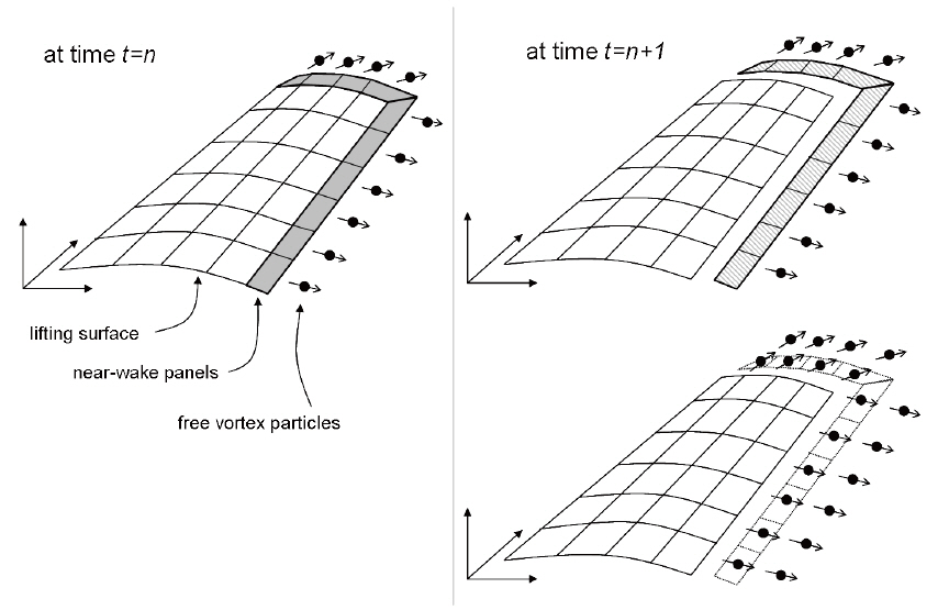
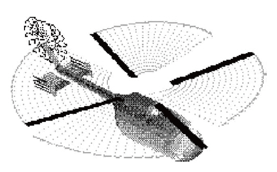
Since there is no commercially available software available with all the above capabilities, Carleton University has started to develop its own rotorcraft simulation code, called SMARTROTOR in 2001 (Cesnik et al., 2004; Khomutov, 2010;Nitzsche and Opoku, 2005). For the aerodynamic module, the code employs a discrete vortex method for the freestream and a panel method combined with the French Aerospace Lab,ONERA’s dynamic stall model for solid surfaces, a concept developed jointly with the National Technical University of Athens n Greece (see Fig. 2 for an illustration of this concept). Note that both these methods are incompressible in nature. For the structural module, a beam model is used for the blades, with either cantilevered or hinged boundary conditions at the root. The structural model also considers a multi-body dynamics model of the hub, allowing to model the masses, location and stiffness of all hub components,including the pitch link. The code is capable to simulate full helicopter configurations very efficiently, with as much as 35 rotor revolutions per day on a single processor computer(Fig.3 ).
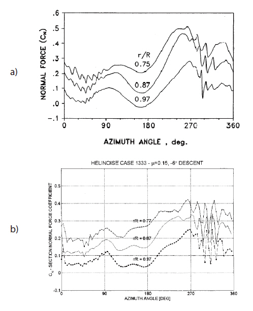
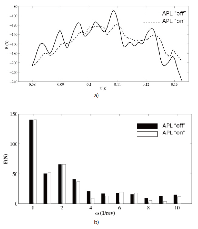
This code was first compiled by Opoku and validated(Nitzsche and Opoku, 2005; Opoku, 2002) against the benchmark HELINOISE experimental data (Splettstoesser,1993). The Smartrotor code proved to be an excellent tool for predicting rotor loads as well as noise, as illustrated in Fig. 4. Note again that these results do not include compressibility effects since discrete vortex methods and panel methods are incompressible in nature. Using the very same code, Oxley et al. (2009) implemented a Smart Spring as a replacement for the conventional pitch link and completed the feasibility studies of the APL for reducing vibration or noise. As an example, the pitch link loads with and without the APL activated are shown in Fig. 5. Later, Ulker (2011) implemented the ACF and identified the optimum actuation schedules for reducing vibration.
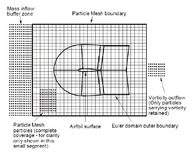
In the meantime, research has been started to improve the fundamental deficiencies of the code. Oxley (2009) has developed a new compressible formulation for the discrete vortex method and combined is with a grid-based Navier-Stokes solver (Fig.6 ). This should allow to capture both transonic effects and flow separation (and thus dynamic stall)as well the correct ageing of the tip helical vortices with the same code. It has been demonstrated to capture transonic BVI in 2D and is yet to be extended to 3D. Parallel to this,possible improvements to the structural model have been explored by Ghorashi (2009), Ghorashi and Nitzsche (2008, 2009), and Gransden et al. (2005). Ghorashi has replaced the 1D beam model with a semi-3D variational asymptotic beam structure, allowing to model chordwise variation of the blade properties as well as active fibre composite structures in the future (such as that of an ATR), thus opening the avenue to model not just the aerodynamics but also the structural side of actively controlled systems. Gransden et al. (2005), on the other hand, has developed a novel method to model fully articulated hubs.
For determining the aerodynamic loads acting on the ACF,as well as the flap’s ability to mitigate the negative effects of dynamic stall, a 2D grid-based Navier-Stokes solver called Carleton multi-block (CMB) was used by Davis et al. (2005).
5. Experimental Infrastructure
Recall that the ultimate goal of the SHARCS research project is to experimentally demonstrate the hybrid control concept in a wind tunnel test campaign. Prior to entering a wind tunnel, one needs to build a scaled fully articulated rotor as well as to conduct extensive whirl tower (or centrifugal)testing to verify the safety and functionality of the individual actively controlled systems as well as that of the rotor. A scaled rotor rather than a full-scale one is required because
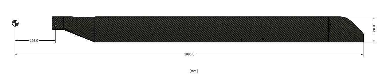
most wind tunnels are not large enough to house a full-scale helicopter rotor. Carleton University’s scaled rotor is of 1.096 m radius, thus corresponding to a 1:5 scaled BK-117 rotor.The rotor is 4-bladed, with a root cut out of e = 11.5%, i.e. the blade bolts are located at 126 mm radius (Fig.7 ). Prototypes of the three actively controlled systems designed for this size of rotor had to be tested in a whirl tower facility first.
5.1 The DLR Braunschweig Whirl Tower facility
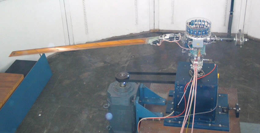
Since at the beginning of the SHARCS project there was no whirl tower facility in Canada, the first wave of whirl tower tests had to be conducted abroad. Thus, the initial centrifugal tests were conducted at DLR’s Braunschweig whirl tower facility (Wierach et al., 2007) in Germany (Fig.8 ). This features an original BO-105 rotor hub driven by a 30 kW DC shunt-wound motor. For 1-bladed tests, a balance weight was mounted on the opposite side of the rotating specimen,which allowed to trim the whole rotating system at different(clockwise) rotating speed. The data transfer was realized by 24 slip rings and by an additional telemetry system with 12 channels available for strain gauge measurements (full bridge or half bridge) and 4 integrated circuit piezoelectric (ICP)channels for accelerometers. A camera, installed in the test room allowed permanent monitoring of the experiment from the control room. Of course, the major drawbacks of testing abroad are the cost and the inability to repeat tests quickly after careful analysis of data. Therefore, there was need to build a state-of-the-art whirl-tower facility in Ottawa.
5.2 The Carleton Whirl Tower facility
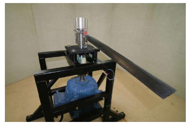
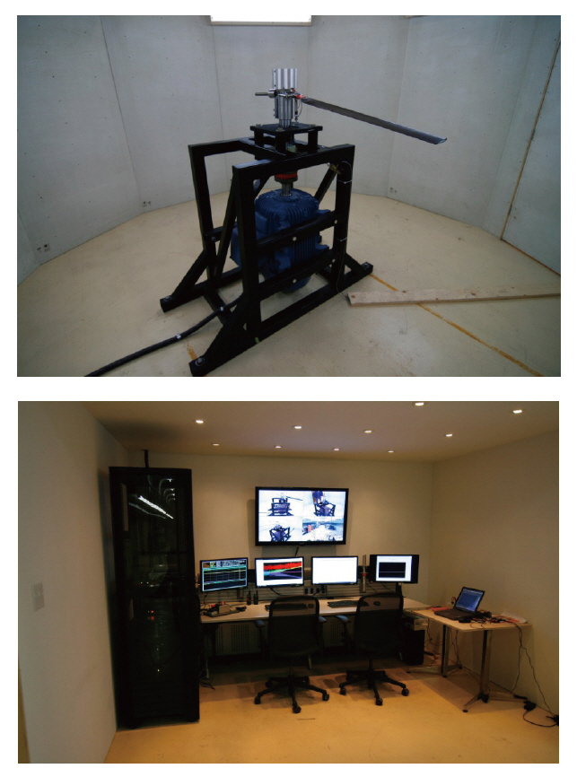
To address the lack of any whirl tower facilities in Canada,the Rotorcraft Research Group at Carleton University(Rotorcraft Carleton) has initiated to build a state-of-the-art facility in Ottawa in partnership with Smart Rotor Systems Inc. and the NRC. The construction and commissioning of this facility has been completed in February 2011. The facility is located at the Institute for Aerospace Research of NRC in Ottawa. It is driven by a 60 HP, 575 V 3-phase, 1,800
revolutions per minute (RPM) motor, which is controlled via a variable frequency drive/transformer. The whirl tower is located in a test chamber with a diameter of 15 ft (4.57 m),as shown in Fig. 9.
The protective walls were constructed from Armorcore level 3 panels, a glass-fibre based protective panel developed for withstanding gunshots. The whole whirl tower facility is monitored by live video and live data collection viewed from an isolated control room.
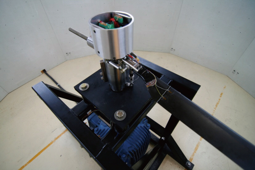
The whirl tower was deliberately designed in a way so that the lowest mode’s natural frequency is beyond the nominal RPM of 1,550. This allows continuous testing without any “blackout periods” in terms of the rotational frequency.To achieve low baseline vibration, the main shaft is driven directly via a flexible coupling. The rotor hub houses both a wireless telemetry system as well as an 8-channel slip ring assembly from Shleifring, as shown on Fig. 10. The wireless system consists of two Microstrain V-link nodes, each capable of transmitting data from 8 differential and 8 strain gauge channels wirelessly.
5.3 Scaled rotor design and manufacturing
Although custom-designed scaled rotor assemblies are available for purchase in the United States, Carleton University has decided to develop this know-how in Canada. Note that a scaled rotor consists of two major components: a fully articulated rotor hub as well as a set of Mach and dynamically scaled blades. Full articulation means the presence of hinges allowing three degrees of
freedom: flapping, lead-lag and feathering (pitch) motions.A 1-bladed counterweight-balanced fully articulated system was designed and built by Carleton University, as illustrated in Fig. 11.
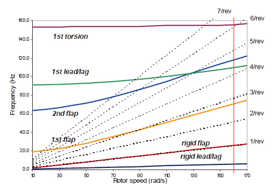
Regarding the scaled blade design and manufacturing,first let clarify that Mach scaling means keeping the same tip Mach number between the scaled and full-size blades. This was set to Mach 0.54 for the SHARCS scaled rotor, thus yielding a nominal rotational frequency of 1,555 RPM. Dynamic (or aeroelastic) scaling, on the other hand means ensuring that the structural response of the scaled blade is identical to that of the full-size blade. This is achieved by matching two parameters at the same time: the stiffness distribution (or the fan plot) of the blade as well as the Lock number. The fan plot depicts the variation of the blade modal frequencies as the rotational speed increases (Fig.12 ). The Lock number, on the other hand, represents the ratio of aerodynamic and inertial forces and implies really a constraint on the blade mass. Typical target lock numbers are in the range of 5-8.
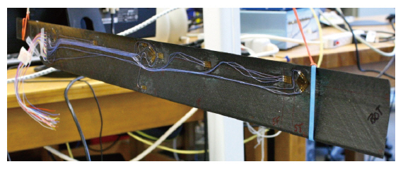
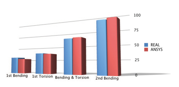
An iterative design process was developed by Carleton University’s three researchers, Ghorashi et al. (2006) and Khomutov (2010), Mikjaniec (2006), which inputs are the geometric and dynamic similarity requirements while the output is the composite blade layup. During the design process, the German LamTech, the previously described Smartrotor and the commercially available ANSYSCFX software were used. The scaled blades were then manufactured in-house out of carbon-fibre composite, and instrumented with 32 strain gages from inside (Fig.13 ), thus allowing careful testing and validation of the computational results (Fig.14 ). It is can be seen that there is excellent comparison between computation and experiment. Details of the blade design and instrumentation are available in Feszty et al. (2008). The complete scaled rotor assembly is shown in Fig. 15.
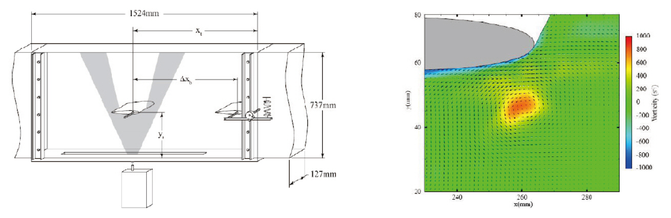
In addition to the above facilities, another unique experimental facility was utilized for understanding the fundamentals of vibration and noise generation on helicopter rotors. This is the so-called “2D vortex wind tunnel” at Carleton University, which was designed specifically to study airfoil-vortex interactions, i.e. the 2D equivalent of BVI. Three graduate students have worked on the development of this wind tunnel: Brassard (2005) on the design and construction,Wilkins (2005) on the commissioning and Schmidt (2010)(with Burwash [2007]) on setting up the particle image velocimetry (PIV) system and the vortex generator. The wind tunnel is of vertical closed-circuit type, with a 1.8 m long
0.127 m x 0.635 m test section. It is driven by a centrifugal blower, which, via a 10:1 ratio contraction and can produce a maximum test section velocity of 85 m/s (Mach 0.25) at 2.1%turbulence intensity level. The tunnel features a pitching airfoil style vortex generator (Fig.4 ), which is 3 chord lengths ahead of the test airfoil to minimize interference effects.The flow around the test airfoil is visualized via an olive oil seeding based PIV system, the timing of which is carefully adjusted to the vortex generator activation (Fig.16 ).
This completes the description of the computational and experimental tools used for developing the three actively controlled systems to be embedded in the SHARCS scaled rotor. Let us now review the progress made in developing the individual active control systems.
Recall that the ACT is supposed to enable to set a certain constant tip angle for the duration of a specific flight regime.This should allow to increase the BVI miss distance and thus to reduce noise and vibration. Thus, the actuation requirement for the ACT has been defined by deflecting the blade tip downward by 20° over about 30 seconds time. At this stage of the design, the ACT is treated as an open loop static controller, i.e. upon detecting increased noise the ACT is set by the control person/pilot to a desired deflection.
There will be two types of loads acting on the ACT : the hinge moment from aerodynamic loads and the hinge moment from centrifugal loads. Since the tip will be moving very slowly, the hinge moments arising from inertial loads can be neglected. The aerodynamic loads were determined from a blade element momentum theory analysis for hover with an
“equivalent tip speed” corresponding to the tip speed of the advancing blade in μ = 0.31 advance ratio forward flight. The hinge moment from aerodynamic loads was thus calculated to be 7.37 Nm. The hinge moment from centrifugal loads was enormous since the centrifugal acceleration at the center of mass of the blade tip is about 2,960 g’s, i.e. each gram of mass feels like 2.96 kg. Assuming 30 g mass for the composite blade tip, the hinge moment from centrifugal loads was determined to be 15.50 Nm. Thus, the resultant hinge moment acting on the blade tip is 22.87 Nm.
The resultant hinge moment acting on the ACT is very large. At the same time, the moment arm available to counter-act this moment is very small, only 9.2 mm, since it is limited by the internal space (i.e. height) of the scaled blade section. This contradiction meant real challenge in designing a suitable actuation mechanism for the ACT, and a number of new design options were considered as potential solutions. One interesting idea was the use of shape memory alloy (SMA) wires for actuation (Lynch et al., 2005), however this proved to be not feasible due to the insufficient force provided by the SMA wires and/or the small moment arm inside the blade. It was concluded, however, that the idea should be revisited for full-scale ACT applications, where SMA actuation might be feasible.
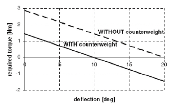
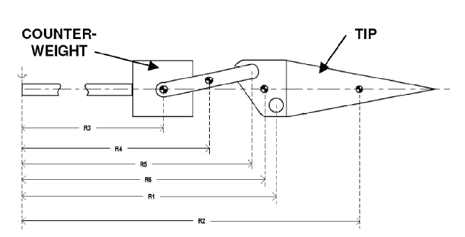
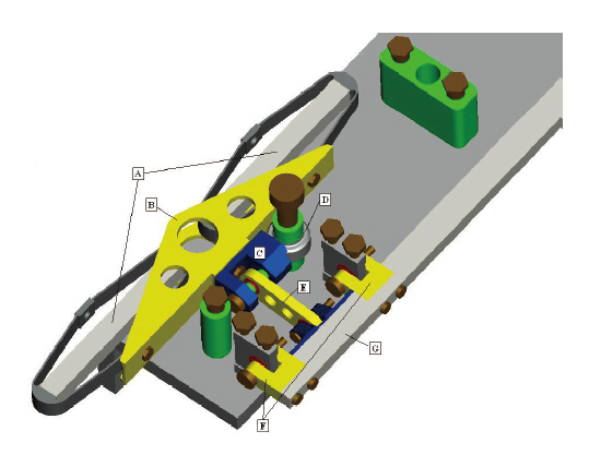
Next, a screw-jack mechanism was considered, which would be driven by a motor of low RPM and large torque.Although the small moment arm problem is avoided in this concept, the extreme torque requirement called again for a very large motor, outside the acceptable scales at the blade tip. However, it was recognized that the large torque requirement for such concept could be reduced by making use of the extreme centrifugal acceleration acting at the tip,i.e. by employing a counterweight concept (Fig.17 ). The counterweight would push the equilibrium point of the ACT mechanism from 0 degrees to the middle of the tip deflection range (10 degrees), and thus could essentially halve the torque requirement on the motor (Fig.18 ). Note from Fig.18 that the equilibrium point is moved to the mid-point of the deflection range (10 deg), thus halving indeed the overall requirement on the shaft torque.
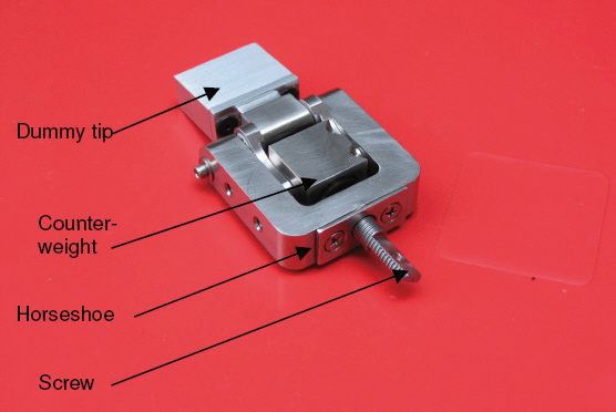
The prototype screw-jack mechanism with the counterweight concept is illustrated in Fig. 19. It consists of a horseshoe with a threaded hole in which the screw rotates and moves the (heavy) lead counterweight in the radial direction. At the same time, the counterweight is pulled outwards by the centrifugal load, thus easing the requirement on the torque to be supplied to the screw.
To minimize blade stresses, the subsystem masses located at the outboard portions of the blade should be minimized.By this, the total centrifugal load acting on the blade can be kept at minimum. For this reason, the motor driving the ACT mechanism was proposed to be placed close to the root and connected to the tip via a light composite torque rod. An additional benefit of this arrangement is that the motor will be exposed to less centrifugal acceleration during operation.Since very few motors are designed to withstand axial loads(i.e. they have radial bearings instead of thrust bearings) the motor should be oriented perpendicularly to the centrifugal load.
The shaft torque was calculated from standard screwjack mechanism equations for a given axial load acting on the thread. Working backwards from the tip, the forces on the individual components of the ACT mechanism were calculated from a free body diagram. From this, the force acting on the counterweight was found and translated into a 1.44 Nm shaft torque requirement for the motor (not including transmission losses). This is the maximum shaft torque required at the maximum, 20 deg tip deflection and its variation with tip deflection has already been illustrated in Fig. 18.
A Maxon A-22 motor with a Maxon GP22C off-the-shelf planetary gearbox was selected for diving the ACT unit.The motor and gearbox characteristics are shown in Tables 2 and 3.
The combined shaft output torque, after gear reduction and 58% of losses, can be calculated from the power and RPM available at the gearbox output. The power output from the gearbox will be 42% of the input power, i.e. 2.52 W. The output RPM after gear reduction will be 7.58 RPM,i.e. it would take only 16 seconds to deflect the tip down 20 degrees (with about 2 revolutions required to complete this deflection). Thus, the useful shaft torque out from the gearbox will be 3.17 Nm, well above the required 1.44 Nm.
The total mass of this installation is, however, 148 g, which is a significant mass relative to the expected total blade mass(in the order of ~500 g).
[Table 2.] Maxon A-22 motor characteristics
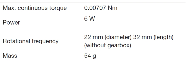
Maxon A-22 motor characteristics
The motor diameter is 22 mm and as such, it offers a possibility to implement it inside the blade at the root, if the blade structure is locally widened and thickened at the root.Figure 20 depicts this design option. Although the blade drag would increase slightly, the overall effect on rotor power is expected to be marginal due to the low velocities at the root.Also note that the torque rod now would involve a universal joint to enable to orientate the motor perpendicularly to the centrifugal load.
Due to the total mass (148 g) and size (2 times thicker than the blade) of the driving unit, this motor is still not ideal for the ACT mechanism and so it would be interesting to challenge the electronics industry to develop smaller motors.
Since the above configuration requires significant alterations to the blade root, it was not considered to be included in the current iteration of the SHARCS wind tunnel model. Instead, the blades will be tested without the motor and torque rod, with a simplified, manually adjustable ACT unit installed at 90%R. Note that this simple device is very light, only 4 grams. This is because the heavy lead counterweight was not required and only a light Titanium mechanism has been incorporated instead. This is the configuration proposed for wind tunnel testing.
[Table 3.] Maxon GP 22C planetary gearbox characteristics
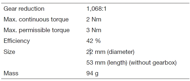
Maxon GP 22C planetary gearbox characteristics
The ACF supposed to reduce either vibration or noise,depending on the actuation schedule. The flap geometry of 65% to 85% radius in span and 15% in chord length have been selected . This was identified by Feszty et al. (2004) and Kloeppel and Enenkl (2005) as the most efficient combination in terms of a) aerodynamic efficiency, for which the flap should be as much outboard as possible, but not beyond 90%radius where tip losses would dominate and b) the power to aerodynamic efficiency ratio, for which the 15% chord length flap was shown to be the optimum.
The desired actuation frequency shall be of at least (N+1)/rev (i.e. 5/rev for the SHARCS scaled rotor), which was computationally identified by Davis et al. (2005), Feszty et al. (2004), and Ulker (2011). Although the desired flap deflection amplitude should be as large as possible (some studies show that even 20 degrees could be useful [Feszty et al., 2004]), what is commonly achievable nowadays is rather in the range of 4-6 degrees. Therefore, for the SHARCS rotor 4 degrees downward only amplitude was set as the goal,mainly to ease the requirement on the ACF mechanism due to the relatively small size of the SHARCS blade. Note that this can be used for an upward-downward deflection pattern if required by setting the flap starting angle to 2 degrees as default.
There will be three types of loads acting on the flap: a)the hinge moment from aerodynamic loads, b) the hinge moment from inertial loads and c) the hinge moment from the tangential component of the centrifugal force. Note that this latter one can be significant since the centrifugal acceleration at the centre of mass of the flap, at 75%R, is just over 2,000 g’s.
The hinge moment from aerodynamic loads was evaluated by using a 2D CFD analysis via using the CMB in-house Reynolds averaged Navier-Stokes solver (Davis et al., 2005) was used for the simulations. The flow conditions corresponded to those occurring at 75%R (midpoint of the flap) on the advancing blade in forward flight at μ = 0.3 advance ratio. Steady simulations considering 10 deg angle of attack (AOA) and 4 deg downward flap deflection were performed. Note ade of carbon fibre composite with the mass of 13.5 g and center of mass located at 1/4th of the flap chord,i.e. 11.25%c from the trailing edge of the airfoil. The angular acceleration was calculated from a sinusoidal flap defection occurring at 150 Hz (7/rev actuation), representing the upper limit of the piezo actuators (to be discussed later) instead of the required 5/rev frequency. From these, the inertial hinge moment was estimated to be 0.00636 Nm. As can be seen, the inertial hinge moment appears to be insignificant relative to the aerodynamic hinge moment, which will be thus dominating the actuator selection.
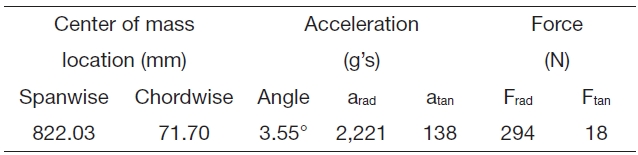
Since the flap or the ACF mechanism with the actuators lies beyond the quarter chord line of the airfoil, the centrifugal force acting on them will create a radial and a tangential component. The tangential component will have two implications: a) it will act against the pulling force created by the piezoelectric actuators and b) it will create a “righting moment” on the flap when it is deflected downwards. To illustrate the magnitude of the two components of the centrifugal force, the centrifugal acceleration equivalents are shown in Table 4 below for the flap center of mass and the ACF mechanism center of mass.
One can see that the tangential component is not insignificant (equivalent to 1.8 kg of force) but relatively small in comparison to the radial force component. The ”righting moment” created on the flap was found to be 0.004 Nm, i.e.an order of magnitude smaller than the aerodynamic hinge moment.
Also, there will be a force from the tangential component of acceleration acting against the actuator force within the ACF mechanism, and this might be important to consider once the component weights are known. The radial loads arising from the centrifugal acceleration have to be supported by the flap hinges and the internal structure of the ACF mechanism.
Based on the above analysis, the resultant hinge moment acting on the flap at 4 deg deflection was calculated to be:
Mtot = Maer + Minertial + Mcentrifugal = 0.048 + 0.006 + 0.004= 0.058 Nm
This is the load the ACF actuators should be capable of overcoming.
Two design concepts were considered--both based on a linear piezoelectric actuator, which linear displacement is converted to angular displacement of the flap. The difference between the two concepts is that while the first one (ACF1)is a slider-crank mechanism (Fig.21 ), the second one is a slider-cam mechanism (Fig.22 ). ACF1 uses miniature ball

Radial and tangential components of centrifugal accelerationand force acting on a composite flap of 10 g mass
bearings and rigid links to enable the desired motion of the flap. However, since these proved to lead to deteriorated performance under increasing rotational frequency, the second concept, ACF2, was designed to address this problem and eliminated all bearings from the system. Nevertheless,both concepts shared the same idea in terms of actuation.
Based on the hinge moments calculated above, and assuming 2 mm moment arm for the flap, the total actuator force required for the ACF could be calculated as 29 N.To satisfy this requirement, two APA 200M piezoelectric actuators from Cedrat (Meylan Cedex, France) were selected to be employed. Each of them is capable of delivering 73 N block force (at zero displacement) or 230 m of maximum displacement at the frequency of 150 Hz.
The two actuators were be installed in parallel, i.e. side by side (Figs. 21 and 22) so that their joint force is doubled while their joint displacement remains the same. The reason of selecting two actuators in parallel is that it is expected that due to the excessive centrifugal loads acting on the ACF
components, quite significant mechanical losses will have to be overcome by the actuators. Another reason for selecting the APA 200M was the space limitation: this was the smallest actuator from Cedrat, is fitting inside the 9.2 mm high internal space of the blade. Note that the link lengths attached to the actuator were optimized to achieve maximum deflection,which full details are described in Feszty et al. (2008).
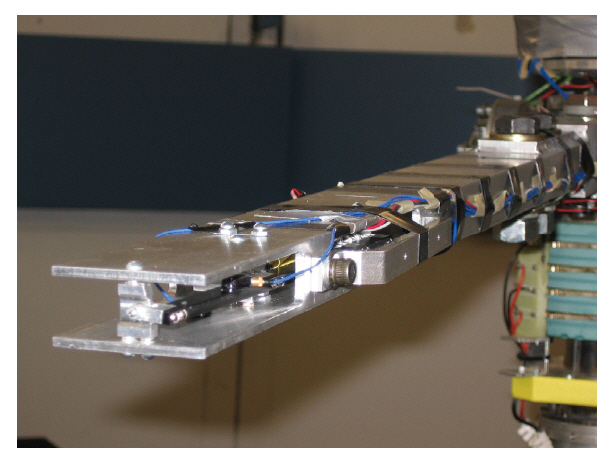
The ACF1 design prototype was tested with a dummy flap (machined out of plastic) at the DLR Braunschweig whirl tower facility in November 2006. The goal of the tests was to verify the functionality of the mechanism under extreme centrifugal loads. The flap mechanism was installed into an off-the-shelf rectangular cross-section Aluminum beam, with the ACF1 center of mass located at the actual radial location. To avoid in-plane bending moments, the Center of Mass was located on the axis of the beam and rotated 3.5 deg to reproduce the tangential component of the centrifugal force acting on it. A load cell was installed to monitor the actuation force, while accelerometers and a Hall effects sensor was used to monitor flap deflections. Figure 23 shows the experimental setup. The system was tested at a range of speeds between 400 RPM and 1,550 RPM at 200 RPM increments. At each RPM, a sine sweep input signal was imposed, from which the results were reduced to frequencyamplitude data and a flap deflection vs. RPM graph, shown in Fig. 24.
It can be seen from these results, that the ACF1 was able to produce about 2 degrees of deflection up to 800 RPM only.Beyond that, the flap deflection was deteriorating, reaching about 1 degree at the nominal speed of 1,555 RPM. After analyzing the possible causes for this result, it was concluded
that the mechanism was likely to lock under the extreme side force due to friction on the roller and possibly at the hinges too. As a result, it was decided that it is necessary to redesign the flap mechanism with less moving parts, and hence the design of version ACF2 was initiated. However, instead of building ACF2, an even better, entirely original third concept(ACF3) has been proposed and tested. This is unique in a way that it has no moving parts and is externally mounted, thus allowing easy maintenance and replacement. Experimental results of this new concept are expected to be published shortly.
The APL is Carleton University’s most unique technology: it is the only existing active control system designed deliberately to alter the blade root stiffness for vibration reduction?the original motivation for developing thus technology. Beside this, it is also the first electrically-driven high-frequency APL at the time of writing this article. Although a hydraulicallydriven high-frequency system has been developed earlier(Kloeppel and Enenkl, 2005; Roth et al., 2007; Schimke et al.1998), as well as an electrically driven quasi-steady system lately (Fuerst et al., 2011), none of them can offer the two most desired features: electrical drive and high frequency actuation at the same time.
8.1 APL: a technology enabling stiffness control
The idea of “stiffness control” was first conceived by Nitzsche in 1993 (Nitzsche and Breitbach, 1994; Nitzsche et al., 1993) and later independently confirmed by Gandhi in 1999 (Anusonti-Inthra and Gandhi, 2000, 2001). The basic idea is to cyclically change the blade root stiffness to reduce vibration. It has been shown by both Nitzsche and Gandhi, that this can be a very effective way of reducing rotor vibrations. The question was: can a technology be developed,which can adaptively change the root stiffness of a blade?
In 1999, Nitzsche has proposed a generic concept?called smart spring?as a possible technology, which could adaptively change the stiffness of any structure (Nitzsche, 1996; Nitzsche et al., 2005). The concept consists of a combination of springs and piezoelectric actuators. The question was again: can a practically useful smart spring be built?
Since 2003, the main goal of the Rotorcraft Research Group at Carleton University in Ottawa, Canada, was a) to build a practically feasible Smart Spring and b) to demonstrate experimentally, that rotor vibrations can be reduced by controlling blade root stiffness via this smart spring.
It was proposed that the smart spring should replace the conventional pitch link, so that the torsional stiffness of the blade can be controlled. This seemed to be the simplest and most efficient method to control blade root stiffness (one could also think for example of some sort of active fibre composite at the blade root, but this would require huge energy input, if feasible at all). Since the torsional mode is coupled with the flapping and lead-lag modes, it will then be possible to control all modes by controlling the torsional stiffness only.
The smart spring replacing the conventional pitch link was named as “active pitch link” within the context of the SHARCS project (although one can view this as a semi-active system since it does not have full authority to counteract pitch link loads?this capacity depends on the instantaneous stored energy in the spring.) Nevertheless, this smart spring based APL can now be used for four possible purposes:
1) To control pitch link vibrations (as shown in Richardson et al. [2011]).
2) To practically realize the “stiffness control” concept for reducing rotor (and not just pitch link) vibrations.
3) To enhance the effectiveness of a blade-based flow control device (such as the ACF or an ATR blade) for reducing rotor vibration. (Note that these flow control devices require LOW blade torsional stiffness for enhanced effectiveness when they work in the “aeroservoelastic mode”. A permanently low blade torsional stiffness is undesired but it can now be achieved for short periods of time?when it is desired and safe?via the APL.)
4) To simultaneously reduce vibration and noise, when combined with a flow controlled device (such as the ACF or ATR). (Note that with one system only?such as the ACF?when vibration is reduced, noise goes up and vice versa. However, a common theorem of Control Theory is that for two control objectives, one needs two independent control systems. Equipping a blade with both the APL as well as the ACF provides two independent control systems and thus promises to reduce vibration and noise simultaneously. In other words, while the flap scheduling is set to reduce vibration, the pitch link schedule can be set to reduce noise.)
To this date, only the first point has been fully explored and thus, results pertaining to this will be summarized in the rest of the paper. Note however, that the major novelties the APL will become evident when points 2-4 will be explored in the future.
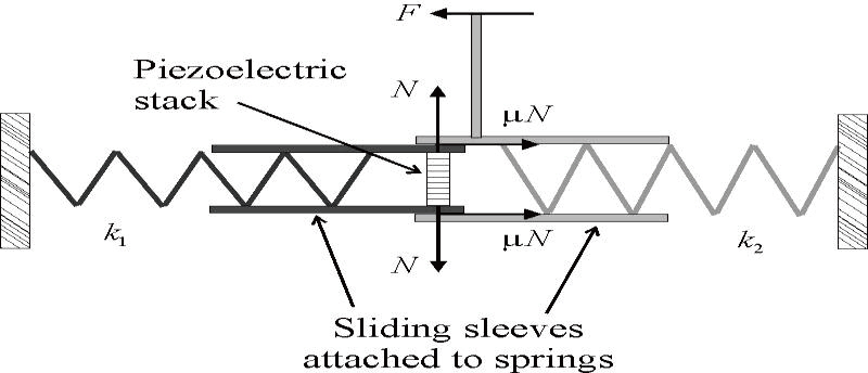
The principle of the APL is summarized in Fig. .25 Note that this configuration does not correspond to the actual APL design for the SHARCS rotor, but it is better suited to illustrate the general operating principle.
In Fig. 25,two springs, k1 and k2 have the ends attached to the opposite walls and a pair of sleeves that can slide one with respect to the other. An external (input) force F is applied to the sleeve attached to the spring designated by k2.A stack of piezoelectric actuators is inserted into the internal sleeve attached to the spring designated by k1.
When the actuator is “OFF,” the two sleeves can move freely and the load path to the base (i.e. the walls) is through spring k2 only. This is the “primary” load path of the APL.When the actuator is turned “ON,” the piezoelectric actuator extends, creating friction between the sleeves, this yielding a resultant load path to the base via springs k1 and k2. This is the “secondary” load path. Thus, the resultant stiffness of the system can be varied between k2 and k1+k2, when the actuator is OFF and ON, respectively.
[Fig. 25.] The smart spring concept on which the active pitch link isbased upon (not actual design).

Harold and Nitzsche has shown computationally, that in general a Smart Spring is suitable to reduce vibratory loads and derived the control law to do so. Within the context of the SHARCS project, the APL shall replace the conventional pitch link. Thus, the blade and the APL become an integral system, which can control the torsional stiffness of the blade in real time.
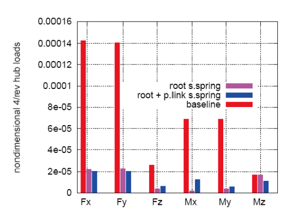
The beneficial effect of varying the stiffness at the blade root for controlling helicopter vibrations was verified independently by Anusonti-Inthra and Gandhi (2000,2001), Nitzsche et al. (1993), Nitzsche and Breitbach (1994).All simulations were performed on aeroelastic models incorporating a complete rotor system. Two examples of these feasibility studies, showing the beneficial effects of using an APL on its own (the combined effect of APL and ACF is yet to be simulated), are shown in Figs. 5 and 26. Figure 5 shows the results achieved by Carleton University’s Smartrotor code (Cesnik et al., 2004; Nitzsche and Opoku, 2005; Oxley et al., 2009), for which the control objective was to reduce pitch link vibratory loads. Note that the frequency domain results (Fig.5 b) show that only the N/rev (where N= 4 blades) harmonics of the vibratory loads are affected,indicating that the pilot controls (collective, which is 0/rev and cyclic, which is 1/rev) remain unaffected. Figure 26 shows the results obtained by University of Roma Tre(Gennaretti et al., 2003; Nitzsche et al., 2005), for which, in contrast to Fig. 5, reduction of vibratory hub loads was the control objective. Although this does not show a case with the APL only, it confirms in general the capability of blade root stiffness control to reduce hub vibratory loads.
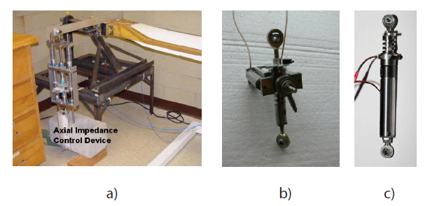
Once the feasibility of “stiffness control” has been confirmed from the computational studies, the question arose: would it be possible to build a working prototype of a Smart Spring based APL? The answer was given by Carleton University, where three generations of prototypes have been designed and built since 2004 (Fig.27 ).
The first prototype (Fig.27 a) was a large scale laboratory model about 0.5 m in length, its purpose was nothing else than to verify in the non-rotating frame that blade stiffness can indeed be affected by introducing a Smart Spring for the pitch link. It used a set of off-the-shelf springs and a large powerful piezo-stack actuator from Sensortech, Collingwood,ON, Canada (type SJ12-70-1010-00). This first generation APL was installed as the pitch link for a full-size Bell 412 blade,which was then exposed to vibration generated via a shaker.Details of these experiments are available in Coppotelli et al.(2008).
The second prototype (Fig.27 b) was designed to fit the scaled rotor hub intended for wind tunnel testing. Since this was the first device designed for actual operation in the rotating frame, strict design requirements had to be met,namely:
Controllability which meant that the frequency and force of the actuator should be sufficient to control the 1st elastic torsional mode.
Observability which meant that monitoring of the vibratory loads, displacements and the actuation force should be feasible so that closed-loop control can be enabled.
Fail safe mode which means that in the event of the power supply, actuator or spring failure, the APL should operate as a solid conventional pitch link.
Size The APL had to be compact enough to fit the scaled rotor hub (108 mm in length) and that it does not interfere with the lead-lag damper at the extremes of the swashplate tilt or stroke.
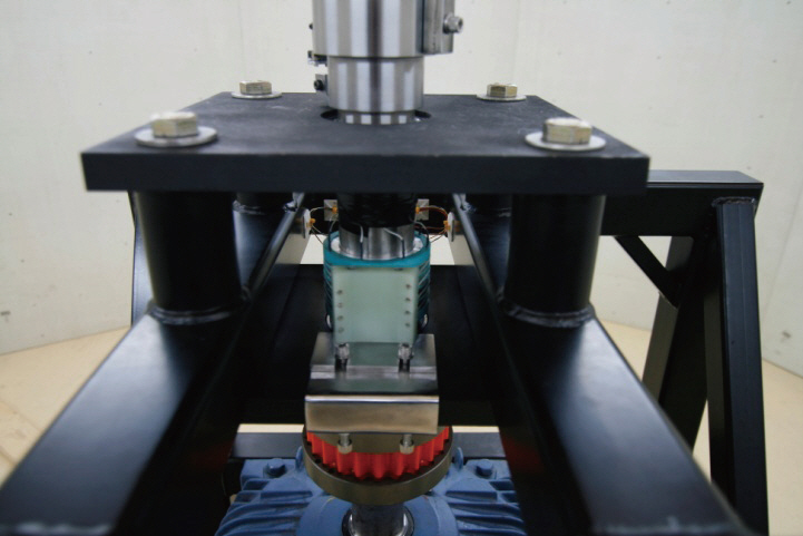
The design of this prototype was obviously much more involved and sophisticated than that of the first one, with a custom-made Titanium spring and two Piezomechanik Pst 150/7/40 VS12 piezoelectric actuators with a maximum block force of 1,800 N and maximum frequency of 200 Hz.Special test jigs were built for the non-rotating and rotating tests.
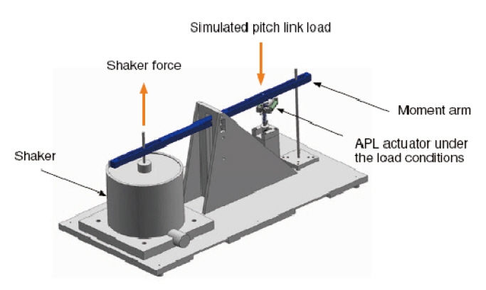
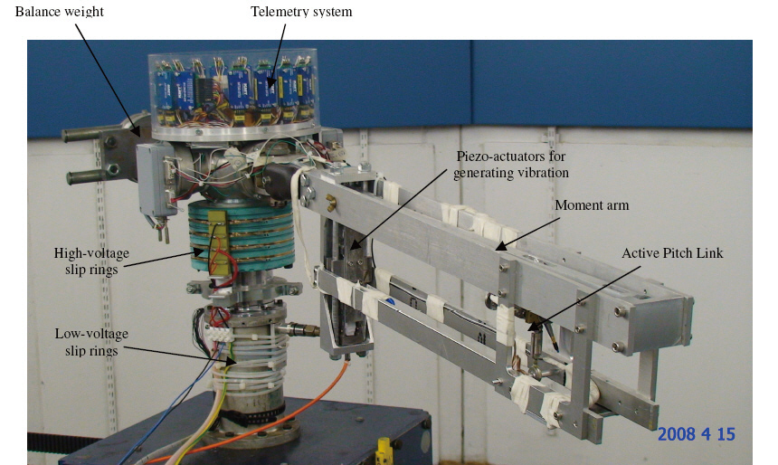
For the non-rotating tests, the test jig consisted of a moment arm and a shaker mimicking the vibrations occurring in the rotating frame (Fig.28 ). Here, the full functionality of the APL was verified (Mander et al., 2008). For the rotating tests, test jig consisting again of a moment arm and a large piezoactuator (the one originally used with the first generation APL prototype) to generate vibrations in the rotating frame (Fig.29 ). This system was tested in an openloop control manner at DLR Braunschweig in the summer of 2008. Details of the tests are available in Feszty et al. (2009).Finally, the second generation APL was installed on DLR’s
active twist blade to determine, whether the blade stiffness can indeed be controlled by altering the resultant pitch link stiffness. These tests are also described in Feszty et al. (2009).For these, University of Rome La Sapienza’s unique “output only” method was used for the modal analysis for the first time in the rotating frame.
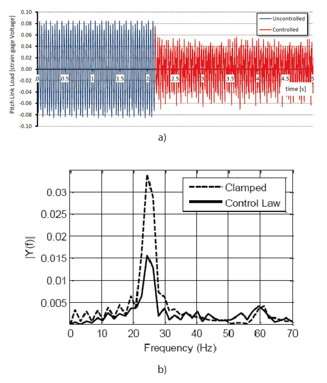
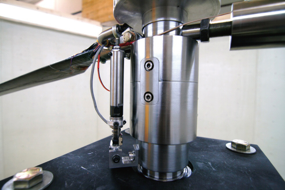
Finally, the most sophisticated and compact 3rd generation APL was designed and manufactured in February 2011 (Fig.27c). The first closed-loop control tests were conducted with this device, showing as much as 55% reduction in the pitch link vibratory loads (Richardson et al. [2011] and Fig.30 ). The functionality of the third generation APL has already been confirmed in the Carleton Whirl Tower facility and currently a fan-system is being constructed to generate periodic controlled vibrations in the rotating frame so that closedloop control tests can be completed. The APL installed in the Carleton Whirl Tower facility is shown in Fig. 31.
9. Conclusions and Future Work
This paper aimed to provide an overview on the current status of rotor-based active control research in Canada. It has been shown that most research is concentrated in the Ottawa area in an innovation triangle consisting of Carleton University, the NRC and Smart Rotor Systems Inc.
It has been shown that in order to conduct competitive research in this field, one first needs to develop a range of analytical and experimental tools. For this reason, there has been extensive research conducted at Carleton University to improve the aerodynamic and structural modules of the existing in-house computational aeroelastic code, Smartrotor. Also, unique experimental infrastructures were built: a 2D PIV vortex wind tunnel, the state-of-the-art Carleton Whirl Tower facility as well as the know-how of designing and manufacturing aeroelastically scaled composite blades has been developed. Beyond this, extensive international collaboration was required to advance research in other areas in a timely fashion.
The above tools and network served to support the SHARCS project, which ultimate goal is to demonstrate the novel hybrid control concept--with the unique “stiffness control” of blades--in a wind tunnel campaign. The SHARCS concept consists of three actively controlled systems: the ACT, the ACF and the APL.
Regarding the ACT system, the conceptual design has been completed and the conclusion was made, this system is better suited for full-scale rotor testing instead of scaledrotor testing. Also, there is need to complete simulations to assess the effectiveness of this system in reducing BVI noise or vibration.
The ACF system’s computational feasibility studies, conceptual design as well as whirl tower tests of the first prototype has been completed. This was a slider-crank system powered by piezoelectric actuators, which suffered from the same problem as many other scaled ACF systems: the deterioration of magnitude of flap deflection as the rotational frequency was increased. To rectify this problem, a second and third generation prototype has been designed and its prototyping and whirl tower testing is planned for the near future.
The APL system is the most unique element of the SHARCS project. It allows to adaptively change the torsional stiffness of the blade and by this to reduce rotor vibration via stiffness control. It can also be used to improve the efficiency of a blade-based flow control device (such as that of an ACF or ATR) as well as it promises to reduce vibration and noise simultaneously, when combined with another bladebased system. The 3rd generation prototype of the APL was demonstrated to reduce pitch link vibratory loads by as much as 55% in the non-rotating frame. Currently, a test campaign is underway to explore this capability in the rotating frame as well as to implement a control law enabling to control the hub load (and not just pitch link load) vibrations.
In conclusion, the prototyping of the ACF and APL systems has been completed, their whirl tower testing is currently underway and are expected to be ready for wind tunnel testing in the very near future.