The field of design and analysis of helicopters has been one of the active areas of research from their inception. It is observed that an accurate prediction on the performance of a helicopter is very essential in the preliminary design of helicopters. There are several existing rotorcraft design programs available in the literature (Davis et al., 1979;Johnson, 2010; Rand and Khromov, 2004). However,statistical data required for the preliminary design is not available in the open literature. The existing frameworks are not based on optimization schemes and need to be updated by applying general optimization techniques available in the literature. In order to develop a multidisciplinary optimization framework using optimization techniques for rotorcraft preliminary design, helicopter sizing and performance computer program (HESCOMP) is selected for improvement (Lim et al., 2009).
The preliminary design stage of the rotorcraft consists of various operations and in each operation design and analysis modules are needed. The analysis tasks include performance and the required power estimation. In the existing helicopter design program, these are usually carried out by using the momentum theory (Ibrahim and Jaafar, 2008; Payne, 1953).Even in the original version of HESCOMP, the required power is determined by using the momentum theory. The limitations of the momentum theory are (i) it does not provide any information on the design of rotor blades to produce a given thrust, (ii) it does not account for linear twist, the tip loss effect, and the reverse flow effect, and (iii) profile drag losses are totally ignored. These limitations are eliminated using blade element theory. In this paper, an explicit form of a more accurate computational model based on the blade element theory and uniform/non-uniform inflow model will be developed. The presently improved framework will be incorporated into HESCOMP. The Drees model will be used to determine the non-uniform inflow.
Blade element theory assumes that each blade section acts as a two-dimensional airfoil to generate aerodynamic loads.The effect of rotor wake is entirely represented by an induced angle of attack at each section. Therefore, this theory requires an estimate of the wake-induced velocity at the rotor disc.This quantity can be provided either from the momentum theory, vortex theory, or non-uniform inflow calculations.The effect due to compressibility, dynamic stall, and radial flow will not be considered in the present analysis.
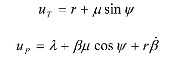
The blade is set at a pitch angle θ measured from the plane of rotation. The tangent and perpendicular velocity components are uT and up, respectively. The resultant velocity V and the inflow angle are given as
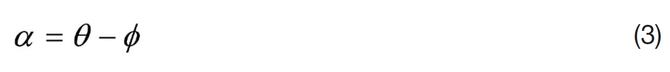
The effective angle of attack of the blade section is
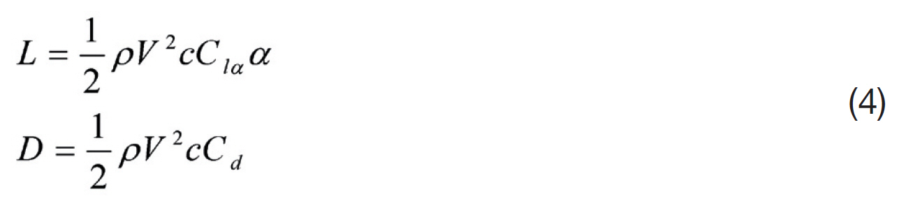
The sectional lift and drag are obtained as
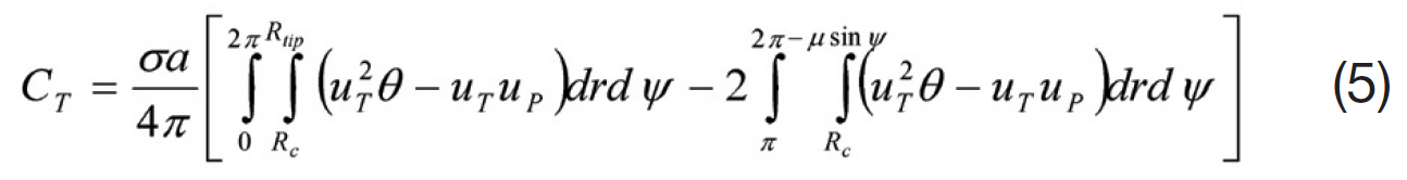
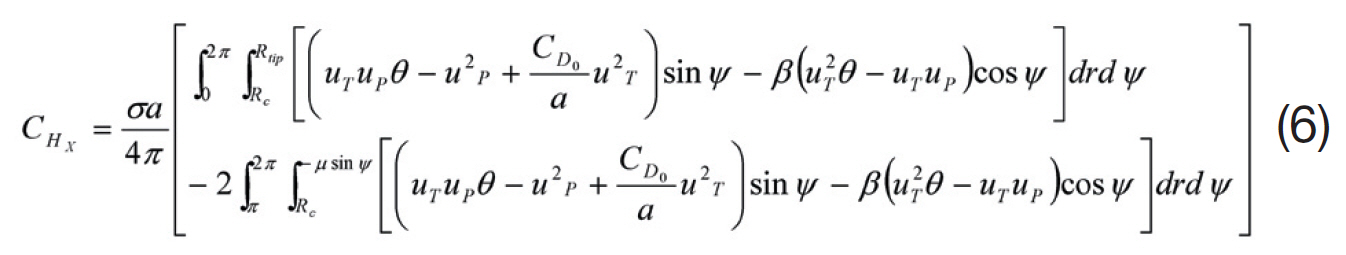
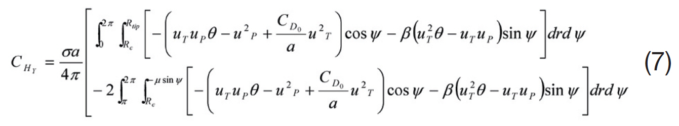
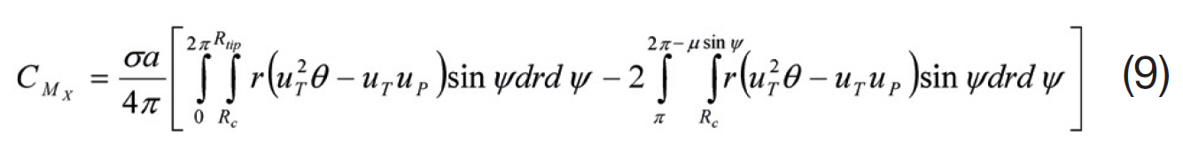
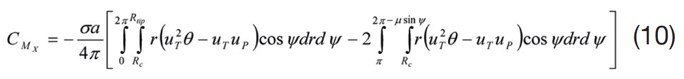
Integrating the blade loads along the span and summing up the loads due to all the blades in the rotor system, one can obtain the hub loads. The average values of these forces can be obtained by integrating over the azimuth and dividing by 2π. For the sake of completeness, non-dimensional hub loads and moments are given below:
? Thrust coefficient:
? Drag force coefficient
? Side force coefficient
? Torque coefficient
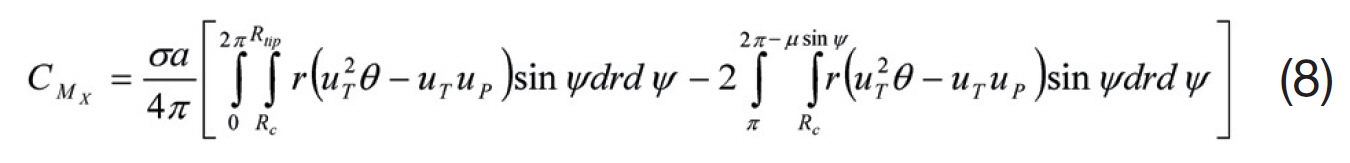
? Rolling moment coefficient
? Pitching moment coefficient
where,
and inflow, λ, is calculated using either the uniform or non-uniform inflow model.
The aerodynamic model requires evaluation of the rotor inflow as a function of azimuth and radial location. There are several inflow models available in the literature. In this paper, both the uniform inflow and Drees non-uniform inflow model are considered as:
2.1.1 Uniform inflow model
In the uniform inflow model, the total inflow through the rotor disc is assumed to be a constant and is given as:

where,
2.1.2 Drees model
Drees (Johnson, 1980) suggested a formula for the rotor induced velocity using the vortex theory with a bound circulation. The Drees expression for induced flow at the rotor disk is given as:

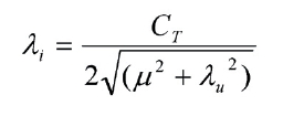
where, λi is the mean induced velocity obtained from the momentum theory:
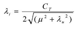
where,
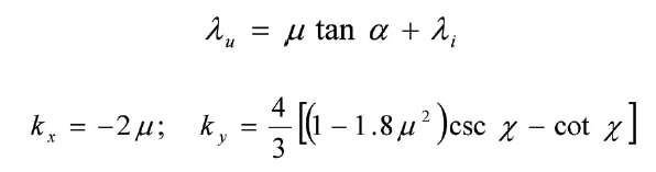
where, χ is the wake skew angle and it is defined as χ = tan?1(μ/λu).
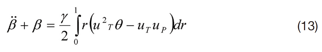
2.2 Flapping equation of the blade
It is a well-known fact that the hub loads are related to the pitch input and the blade response. These response quantities depend on the configuration of the blade model.In this paper, only rigid flapping motion is considered and a simple idealized model of the blade is used (Fig.1 ). The blade is assumed to be rigid and offset-hinged springrestrained.The corresponding flapping equation of motion can be written as
2.3 Forces and moments on the fuselage
The loads due to individual components (main rotor, tail rotor, and fuselage) are transformed to the center of gravity of the helicopter. Using the total loads, one can write the flight dynamic equations of the helicopter. The x-axis is along the forward direction of the helicopter and the z- axis is vertically downward.
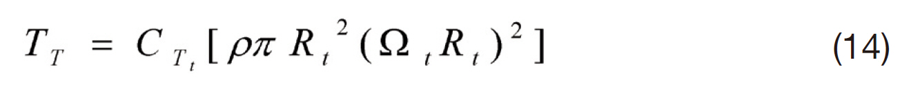
2.3.1 Tail rotor
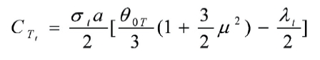
The thrust generated by the tail rotor is derived using the combined blade element and momentum theory. The tail rotor thrust acts normal to the tail rotor plane and in a direction providing compensation to the torque of the main rotor. Tail rotor thrust is given as:
where, the coefficient of tail rotor thrust CTt is defined as:
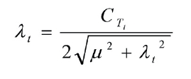
and tail rotor inflow is given by
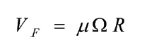
2.3.2 Fuselage drag
Fuselage drag force is proportional to the square of the flight speed and the equivalent flat plate area. Fuselage drag can be evaluated by using the following expression.
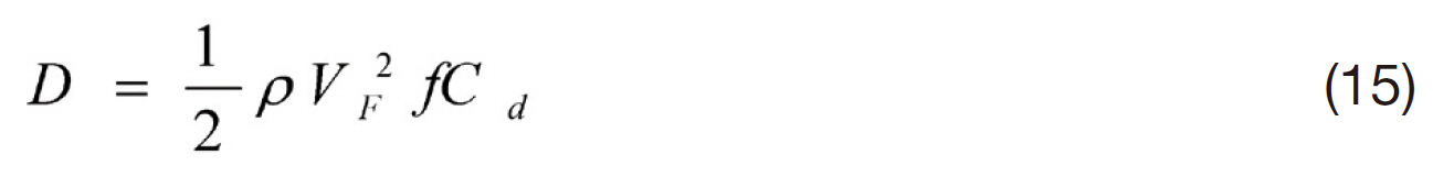
where,
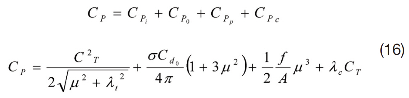
2.4. Required power estimation
The power required by a helicopter can be divided into (i)profile power (P0), power to rotate and translate the rotor;(ii) induced power (Pi), power needed to generate the rotor thrust; (iii) parasite power (Pp), drag power of the parasitic components; and (iv) climb power (Pc), work done against gravity. The total power coefficient is determined using the following expression:
A propulsive trim procedure is adopted to obtain the main rotor control angles, fuselage roll, and pitch attitudes. The corresponding trim equations in non-dimensional form are given as
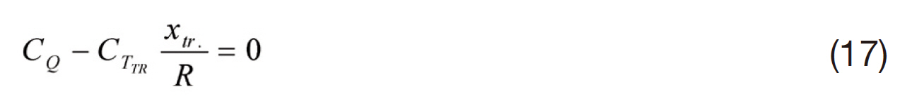
The steps used in the evaluation of the trim and response are described as follows:
1) For the given data including the flight conditions,evaluate the mean rotor inflow based on the all-up weight.
2) Assume the initial values for the trim variables (θ0, θ1c,θ1s, Θ, and Φ).
3) Using the rotor inflow and the assumed trim variables,obtain the aerodynamic loads.
4) Using the blade aerodynamic loads, the blade response,inflow, and trim variables are obtained simultaneously.The Newton-Raphson technique is used to find the blade response, inflow, and trim.
5) With the blade response, inflow, and trim variables, go to Step 3. This iteration will be repeated till convergence in the blade response, inflow variables, and trim variables are obtained.
[Table 1.] Properties of the several helicopters
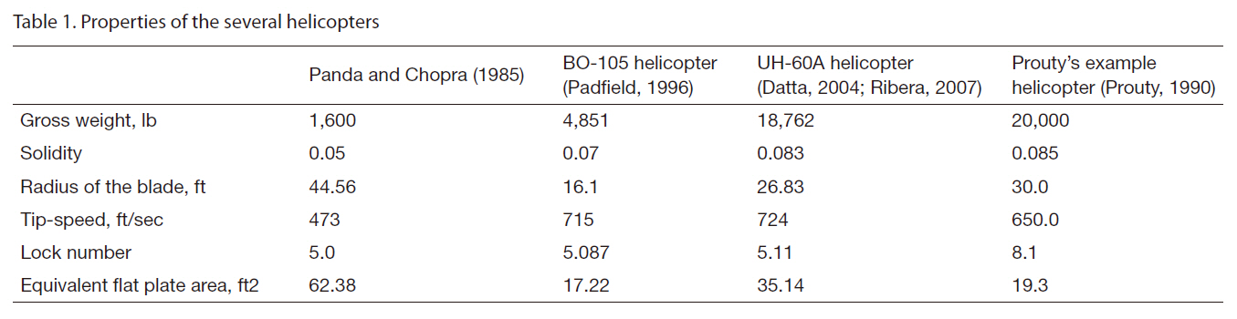
Properties of the several helicopters
Equations (13) and (17) are used to analyze the trim condition of the helicopter and blade response for forward flight using the solution procedure described in the previous section. The parameters obtained from the trim calculation are control angles and attitude of the helicopter. Two sets of results are presented in the following section. The first set pertains to trim and the other corresponds to the power requirement estimation for several different forward flight speeds and helicopters. The helicopter trim is analyzed for different cases to bring out: (i) the effect of aerodynamic modeling and (ii) the influence of forward flight speed.The main rotor blade is modeled as a rigid blade with only a flapping mode. The baseline properties of the several helicopters used for the present trim and required power estimations are provided in Table 1.
Using the two aerodynamic inflow models (uniform and Drees models), helicopter trim is evaluated for several forward flight speeds and compared with those obtained from the flight test data. Figure 2 shows the variation of control angles and pitch attitude of the helicopter in terms of the advance ratio, obtained by the present blade element theory. Figure 2a is obtained from the uniform inflow and Fig.2 b is from the non-uniform inflow. Both results match exactly with those obtained by Panda and Chopra (1985).Figure 3 shows the trim results obtained from the present analysis, HELISIM by Padfield (1996), and experimental data corresponding to the BO-105 helicopter (Padfield, 1996),respectively. Figures 3a and b correspond to the uniform and non-uniform inflow models, respectively. It is evident that the non-uniform inflow model is capable of predicting the lateral cyclic pitch angle more precisely than the uniform
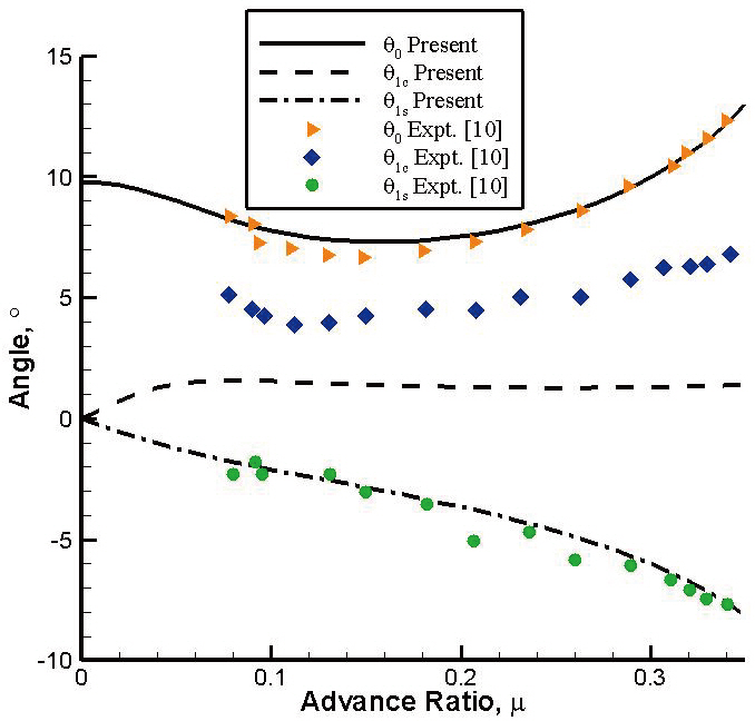
inflow model. For example, at a low forward flight speed (μ= 0.1), the uniform inflow predicts the lateral cyclic pitch angle as 0.06°, whereas non-uniform inflow predicts the angle as 1.06°. At a high forward flight speed (μ = 0.3), the uniform inflow predicts an angle of 0.44°, whereas nonuniform inflow predicts the angle to be 0.82°. It is also seen that the collective pitch angle is predicted much better than that by HELISIM. Finally, the present analysis is used for a UH 60-A helicopter. The relevant data is taken from Datta(2004) and Ribera (2007) and is also tabulated in Table .1The rotor collective and cyclic pitch variations are illustrated in Fig. 4 along with experimental data. It is observed that the collective and longitudinal pitch angles are predicted quite close to the experimental results. The lateral cyclic angle (θ1c)prediction qualitatively matches those of the flight results but with some discrepancies, as does the simple inflow model like the Drees inflow.
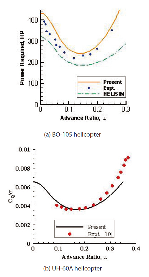
Equation (16) is used to estimate the power required for forward flight. The variation of the induced, profile,parasite, climb, and the total power in terms of the advance ratio is illustrated in Fig. .5 Helicopter properties are taken from Prouty (1990). For the sake of comparison, the result obtained from Prouty’s analysis is also drawn simultaneously.It is observed that there are discrepancies between both predictions. The reason for these discrepancies is due to the difference in the inflow estimation. Figure 6 shows total
power estimation for two different helicopters. Figure 6a shows the BO-105 helicopter result comparison between the flight test result and HELISIM. The power estimation using present analysis shows better correlation. Figure 6b shows the UH-60A helicopter result comparison. The required power estimation correlates well at lower forward flight speeds. However, the discrepancy increases with increase in the forward flight speed. For instance, at a high forward flight speed (μ = 0.37), the present analysis predicts CQ/σ as 0.008, whereas experimental results give the ratio as 0.0091.Overall, the trim angles and power required estimation by the present blade element theory and a non-uniform inflow model correlate well with experimental results.
In this paper, an explicit form of computational analysis based on the blade element theory and uniform/nonuniform inflow model has been developed. The basic idea is to obtain the trim and required power estimation for various helicopter configurations. Sectional and hub loads, power,trim, and flapping equations have been developed in an analytical form. Iterations were carried out till convergence was achieved in the blade response, inflow, and trim. The results regarding the trim and power estimation correlated well with the experimental results. The effect of inflow was investigated numerically. It was shown that the prediction for the lateral cyclic pitch angle was much better by the nonuniform inflow model as compared to the uniform inflow model. The result of the trim and power estimation will be useful in updating the helicopter sizing and performance analysis.