Aerospace structures are subjected to wide variety of forces, which can be classified into two categories?a)conservative forces and b) nonconservative forces.Conservative systems can lose the stability of their equilibrium positions by divergence (static instability) only,whereas nonconservative systems can have two types of instability mechanisms?divergence (static instability) and flutter (dynamic instability). These are known as aeroelastic instability behaviour which is due to highly flexible nature of the structure. Before embarking on this discussion, it will be pertinent to discuss on the elastic stability behaviour of structures.
1.1 Evolution of the problem of elastic stability
The theory of elastic stability, which originated in the works of Euler, is now a very well developed branch of applied mechanics employing many effective techniques and possessing a large number of problems already solved,as well as a very large body of literature. One of the major factors, which contributed to the rapid accumulation of material in the field of elastic stability, was undoubtedly the extremely successful concept of stability and critical force. In the theory of elastic stability it is assumed that for sufficiently small loads the equilibrium of an elastic system is stable,and that it remains so up to the first point of bifurcation of equilibrium forms; thereafter, the initial form of equilibrium becomes unstable. The critical force (or in general a parameter of the force group) is then defined as the smallest value of the force at which, in addition to the initial form of equilibrium,there can exist others, which are very close to the initial form.This concept is to be found as far back as the works of Euler,who defined the critical force as “the force required to cause the smallest inclination of the column”. This approach, or,as we shall refer to it in the future, the Euler method, has enabled us to reduce the problem of the stability of a form of equilibrium to the simpler problem of finding the minimum characteristic value of certain boundary-value problems.
The usefulness of the Euler method in the theory of elastic stability cannot be disputed. It has also been extended to problems of non-elastic stability, expressed in the concept of a “reduced modulus.” However, the Euler method is not universal; its range of application can be clearly defined and a number of mistakes and misunderstandings have occurred in the past as results of attempts to apply the theory outside the range. These factors should be remembered in connection with the Euler method in the theory of stability.
One of these is associated primarily with the development of the non-linear theory of thin elastic shells. As far back as the thirties it was established that in the case of shells a systematic and very significant divergence existed in the values of critical loads given by the classical theory and by experimental results. It was found that for thin shells initial inaccuracies and non-linear effects assume considerable importance, and that the critical forces corresponding to the points of bifurcation of equilibrium are in fact the “upper”critical forces, which are difficult to realize even under the most ideal experimental conditions.
In many cases, stability behaviour is investigated by “the method of small oscillation” around the region of bifurcation.Further, the Euler method is applicable if the external forces have a potential (i.e. if they are conservative forces), and in general is not applicable if they do not. The latter problems are termed as nonconservative problems.
The basic method of investigating nonconservative problems in the theory of elastic stability is the dynamic method, which is based on the investigation of the oscillations of the system close to its position of equilibrium. This draws the theory of elastic stability closer to the general theory of stability of motion and its applications in the theory of automatic control, in the hydromechanics of a viscous liquid and in other fields of mechanics and engineering. The Euler method, which reduces the problem to an analysis of the bifurcation of the forms of equilibrium of the system, can be looked upon as a particular case of dynamic method.
The present review is devoted to the study of nonconservative problems of the theory of elastic stability.Aerodynamic and hydrodynamic loads, the forces acting on parts of turbines and electric machines, and loads induced in parts and linkages of automatic control systems are in most cases nonconservative forces. The classical theory of elastic stability developed primarily as a result of the requirements of industrial, transportation and civil engineering construction. The traditional loads of the classical theory of elastic stability are forces, which have a potential, usually caused by gravitational effects (i.e. “dead” loads). As regards the nonconservative problems of elastic stability, their main interest lies in the development of present-day mechanical,aeronautical and rocket engineering. The subject falls under the terminology aeroelastic instability.
1.2 The follower force problems
The stability characteristic of a slender missile structure subjected to end thrust is a follower force in nature and is a classic example of nonconservative problem of the theory of elastic stability. When the structure is under follower force whose direction changes according to the deformation of the structure, it may undergo static instability (divergence)or dynamic instability (flutter) depending on system parameters, giving rise to unbounded deformation or growth of vibration without bound.
In many practical applications, the applied load is considered as nonconservative if the work done by the forces is path dependent. Follower force, which follows the configuration of a dynamic system, belongs to the group of nonconservative system of forces. Some of the important practical illustrations of follower forces are:
1. the aerodynamic drag forces acting on the body of ro?ckets;
2. the missiles and wings of aircraft carrying jet engines subjected to concentrated follower forces (engine thrust);
3. a cantilever pipe conveying fluid;
4. the forces acting on the rotor of a gas turbine;
5. the forces acting on the links and elements in automatic control system applications; and
6. automobile disk brakes, where the squeezing force acting on the rotating disk is a nonconservative follower force and, etc.
It was shown by Ziegler (1952) that the problem of stability of a nonconservative system can be treated meaningfully only by applying the kinetic stability criterion (that is considering the motion of the system). He also discovered that internal damping may have a destabilizing effect in a
The dynamic instability behaviour under nonconservative forces can be studied by analyzing the nature of the roots of the eigenvalue problems developed in its formulation(Bolotin, 1963).
Let, β : load parameter, Ω : frequency parameter.
The behaviour of the eigenvalues, Ω, of the boundary value problem as the loading parameter, β, varies will be investigated. The response behaviour of any vibration problem is expressed as
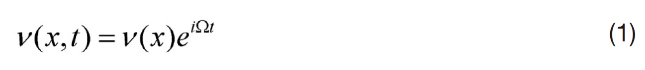
where, Ω = Ω(
If
If
Again if
Ω(
If all the eigenvalue, Ω(
Let us suppose the load parameter
Let, in Eq. (1), s = iΩ, then,

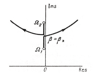
Again, for nonconservative problems, s(β) is complex in nature, i.e.
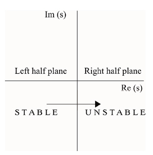
s(β) = Re{s(β)} + Im{s(β)}
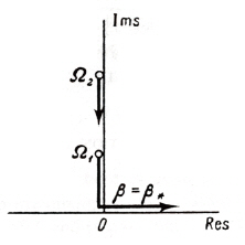
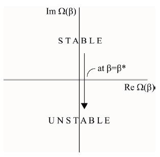
Provided all the exponents remain in the left-hand halfplane,the equilibrium under investigation is stable. For a value of the parameter β = β*, if even one exponent crossing into the right-hand half-plane, the equilibrium is unstable asshown in Fig. 2.
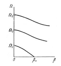
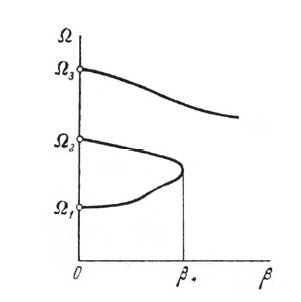
There are two forms of transition from stability to instability.The first is when one exponent s enters the right-hand half plane after passing through the origin of co-ordinates, and remains purely real at least for values of β sufficiently close to the critical values β*, shown in Fig. 3. Corresponding graph of real part of the frequency Ω with β is shown in the Fig. 4.
Here the transition from stability to instability occurs through zero value of the frequency (Re(Ω) = 0). This form of instability is known as static instability or divergence.
If the characteristic components enter the right hand half plane at a point other than the origin of co-ordinates,the form of instability, referred to as flutter, shown in Fig. 5.Corresponding plot of Re{Ω(β)} with β is shown in Fig. 6.The two forms of instability (static and dynamic) differ in behaviour of the disturbances close to the boundary of stability. For the case of static stability, disturbance increases monotonically with time. For dynamic stability, increase in the disturbance is of oscillatory nature.
Summary:
If all the characteristic roots si, i = 1, 2, …, n, (V(x, t) = V(x)est) of the eigenvalue problem are distinct, the necessary and sufficient conditions for stability are that all the real roots and all the real parts of the complex roots should be negative or zero.
If roots st is a positive real number for at least one value of the index i, divergence (static instability) will occur. If roots si is complex with Re(si) < 0 for all i, the system is stable(vibration with decreasing amplitude), but if Re(si) > 0, for at least one value of the index i, a state of flutter will exist.
3. Analysis of Follower Force Problems
3.1 One dimensional structure: beams and columns
A free-free beam subjected to a controlled follower force depicting the nonconservative problem of elastic stability has been the subject of many studies simulating the stability behaviour of flying flexible rockets and missiles. The stability of elastic systems subjected to nonconservative forces cannot be solved by conventional Euler’s approach (Bolotin, 1963)as such systems have both the static instability (divergence)and dynamic instability (flutter) unlike the conservative ones. Beck (1952) was the first to study the stability of cantilevered column under a follower force at the end. Many papers on the vibration stability of cantilevered columns subjected to follower force have been published since then(Chen and Ku, 1991; Pederson, 1977; Sankaran and Rao,1976). In most of the papers, the origin of the follower force was not mentioned and thus no tip mass was taken into account. Sugiyama et al. (1990) have worked on the stability of cantilevered columns subjected to a rocket thrust through both experimental and theory, taking into consideration the size and the mass of the rocket motor. Chen and Ku (1992)investigated eigenvalue sensitivity in the stability analysis with the concentrated mass at the free end. Ryu and Sugiyama(1994) have given an insight into a proper combination of the size, magnitude and rotary inertia of a solid rocket motor for cantilevered Timoshenko columns subjected to a follower force. Langthjem and Sugiyama (1999) investigated on the optimum design for dynamic stability of cantilevered column subjected to a follower force.
In seeking for better understanding of the stability behaviour of flexible space vehicles (missiles, rockets, etc.)there has been some renewed interest in the dynamics of free-free beams. Owing to nonconservative nature of the forces involved, the inertia of the system and other structural and material variations, the solution formulation can often become quite complex. Beal (1965) introduced a direction control mechanism for the follower force to eliminate the tumbling instability of a free-free beam under a follower force. Wu (1975) studied the stability of a free-free beam under a controlled follower force by using finite element discretization with an adjoint formulation. Park and Mote(1985) studied the maximum controlled follower force on a free-free beam carrying a concentrated mass. Park (1987)studied the effects of rotary inertia and shear deformation parameters on the stability of a free-free Timoshenko beam under a controlled follower force. Dynamic stability of a freefree Timoshenko beam subjected to a pulsating follower force has been studied (Kim and Choo, 1998) using the method of
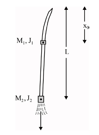
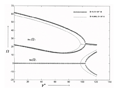
multiple scales (MMS). A general free-free missile structure subjected to end rocket thrust is shown (Fig.7 ). Sugiyama et al. (1999) gave a review on realistic follower forces. Later Langthjem and Sugiyama (2000) presented a detail survey on columns subjected to follower loads. Pradhan and Datta(2006) studied dynamic instability characteristics of a freefree missile structure under a controlled follower force and gave the effect of rocket mass and an intermediate mass on the instability effect of a free-free missile like structure.For the above problem, Fig. 8 shows the plot of real and imaginary parts of the frequency versus the non-dimensional follower force for the beam for certain parameters. It can be observed that as the dynamic critical load is reached, the real parts of the first two non-zero eigenvalues coalesce and the imaginary parts become complex conjugate. This is the condition which corresponds to flutter.
3.2 Two dimensional structures: plates and curved panels
So far the concept of follower forces was discussed with regard to one-dimensional structure, such as Beck’s column resembling missile structures. However, two-dimensional plate/curved panel types of structures subjected to follower forces are also found in the literature and are of practical interest. For example, the wing of an aircraft carrying jet engines is subjected to follower forces (engine thrust) or distributed partial load over a region. Because of flexible nature of these structures, they are prone to divergence and flutter type of instability. Few important studies on the stability of plates and shell type of structures that are reported in the literature are presented here. Culkowski and Reismann (1977) studied plate buckling due to follower edge forces using analytical method considering two boundaries.Farshad (1978) investigated the stability of cantilever plates subjected to biaxial sub tangential load using Galerkin’s method. Leipholz (1978) studied stability of a rectangular simply supported plate subjected to non-increasing tangential follower forces. Leipholz and Pfendt (1983)used Galerkin’s theory to analyse the plate with distributed follower forces acting on the surface of the plate. Adali (1982)investigated stability behaviour of the plate subjected to tangential follower force and an in-plane force for a clamped free plate with two opposite simply supported edges. Higuchi and Dowell (1990, 1992) investigated the dynamic stability of completely free-edged rectangular flat plate by neglecting rotary inertia and shear deformation using modal analysis. It was observed that small damping has a predominant effect on the stability behaviour of a nonconservative system. Kim and Park (1998) investigated the dynamic stability behaviour of rectangular plates subjected to intermediate follower force. Choo and Kim (2000) studied the dynamic stability of isotropic and non-symmetric laminated rectangular plate with four free edges subjected to pulsating follower force.Kim and Kim (2000) studied dynamic stability of an isotropic,orthotropic and symmetrically laminated composite plate under pure follower force considering Mindlin assumption and investigated the effects of shear deformation and rotary inertia under follower force. Zuo and Schreyer (1996)analyzed flutter and divergence instability of nonconservative beams and plates. Bismarck-Nasr (1995) studied the stability behaviour of a cantilever cylindrically curved panel subjected to nonconservative tangential follower forces distributed over the surface and on the free end of the panel. Park and Kim (2000a, b, 2002) investigated extensively the dynamic stability characteristics of a completely free cylindrical and stiff-edged cylindrical shell subjected to follower forces using finite element method (FEM). Extensive review work have been reported by Liew et al. (1997), Qatu (1992) on shallow shell vibration and by Bazant (2000), Bismarck-Nasr (1992),Herrmann (1967), Komarakul-Na-Nakoran and Arora (1990),Langthjem and Sugiyama (2000) on the systems subjected to nonconservative forces.
Most of the researchers have given importance to study the stability characteristics of plate/shell subjected to uniform edge follower forces. However, it is worth mentioning here that such loads are not very common in practice. Many practical situations demand the behavioural aspects of such structural elements under the action of discontinuous/partial edge follower forces with different nonconservative parameters.For example, the skin (panel) of the wing structure of an aircraft carries non-uniform partial in-plane load, making the panel susceptible to buckling. The resulting in-plane stress distribution in the panel, in general, is a combination of tensile and compression stress zones. In a certain domain,when the tensile zone dominates, it gives rise to a stiffening effect. On the other, hand, domination of compressive zone leads to a destiffening behaviour. The results of such studies are important, which can be used in design practice. Further,due to ever increasing use of composite panels subjected to follower forces is of importance, hence a subject matter of this review paper. Effect of damping on elastic stability behaviour for nonconservative systems is also important.Herrmann and Jong (1965) showed the destabilizing effect of damping in nonconservative elastic systems.
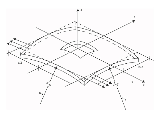
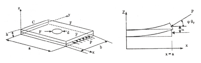
Before going to the review it will be pertinent to provide the mathematic formulation for two-dimensional structures for such studies, which will be of help to the researchers. A composite doubly curved panel subjected to partial edge loading is considered and is shown in Fig. 9.
3.2.1 Mathematical formulation
Strain displacement relations
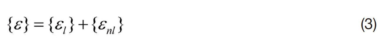
The strain displacement relation consists of two parts:
1. linear strain terms used in the derivation of elastic stiffness matrix; and
2. non-linear strain for geometrical stiffness matrix,
The linear strain displacement relations are:
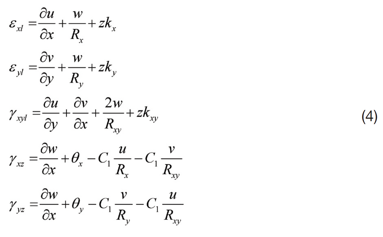
where, the bending strains, kx, ky and kxy are expressed as
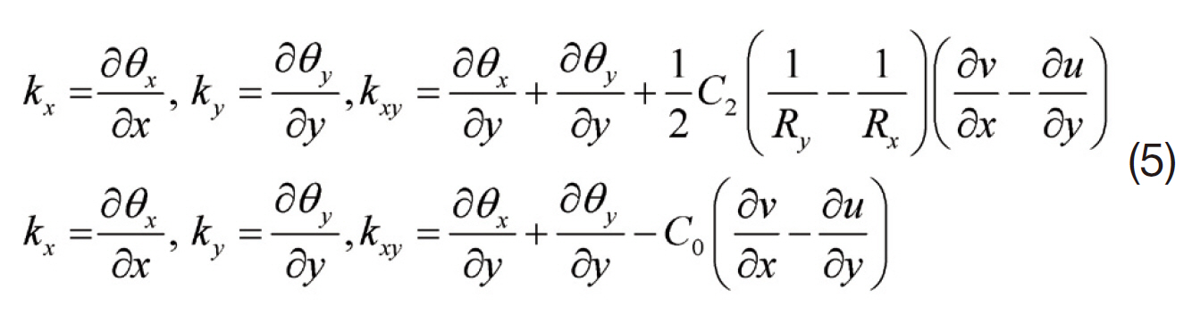
In the above equations, u, v and w are the middle plane displacements along x, y and z directions, respectively. θrepresents the slope of the middle plane of the differential shell element; 1/R represents the radius of curvature; and C1 and C2 are tracers by which the analysis can be reduced to that of shear deformable Love’s first approximation and Donnell’s theories and C0 = (1/2)C2((1/Rx)-(1/Ry)) is a result of Sanders’ theory which accounts for the condition of zero strain for rigid body motion.
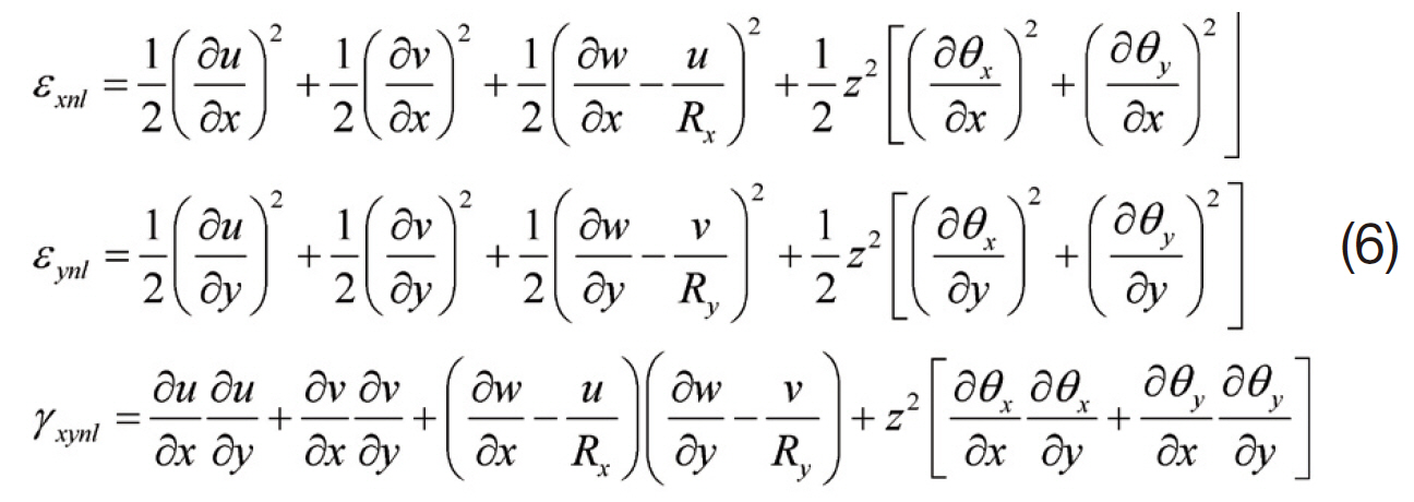
The non-linear strain displacement relations are as per Sanders’ non-linear theory of shells (Sanders, 1963),
3.2.2 Finite element formulation
An eight-node doubly curved isoparametric element is being used in the present analysis with five degrees of freedom u, v, w, θx and θy per node having radii of curvatures Rx, Ry and Rxy.
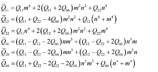
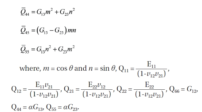
Constitutive relation of a lamina
The constitutive relation of the lamina with reference to any arbitrary axes is given by
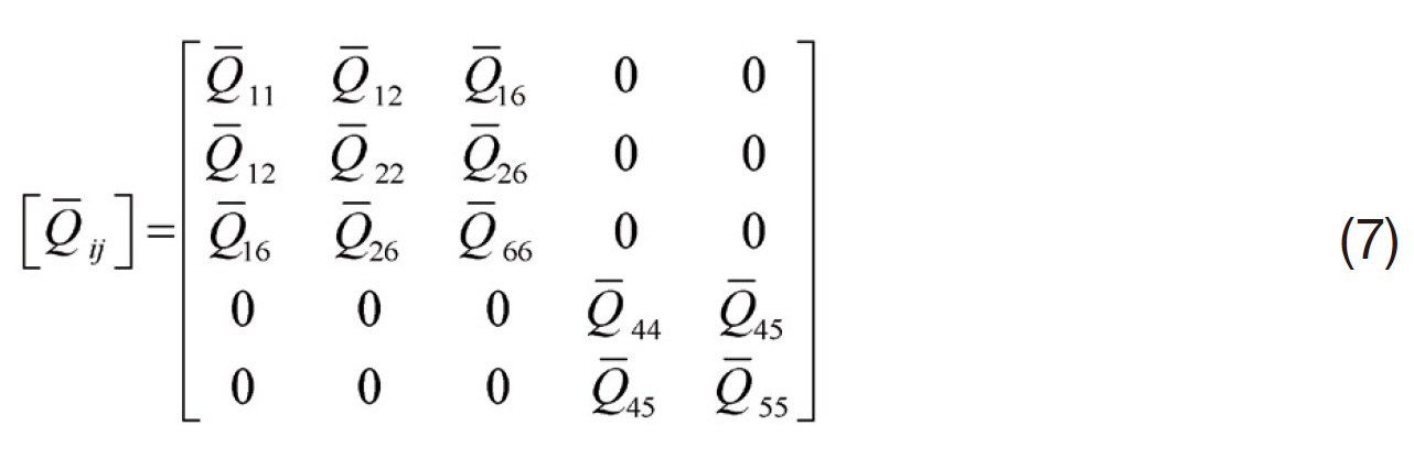
where,
The elastic stiffness matrix corresponding to transverse shear deformation is derived as per Kim (1996).
Stiffness matrix of a laminate
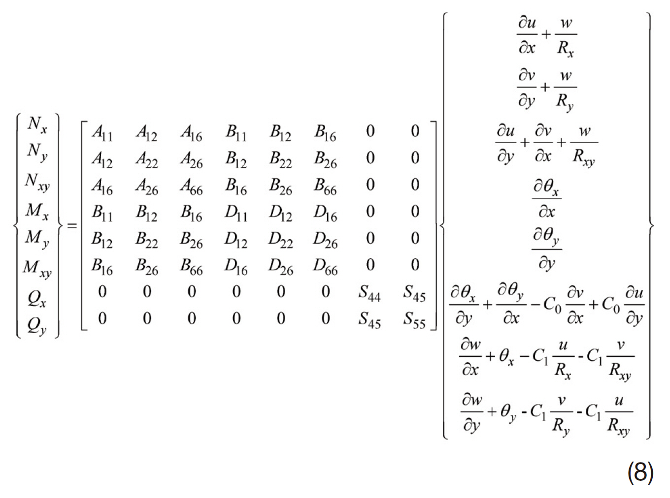
In abbreviated form the above equation is written as,

in which [D] is the stiffness matrix for the composite laminate.
Strain energy due to linear strains
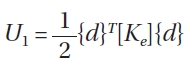
The strain energy U1 due to linear strains in the entire plate/shell panel can be expressed in terms of the stresses and linear strains as given below.
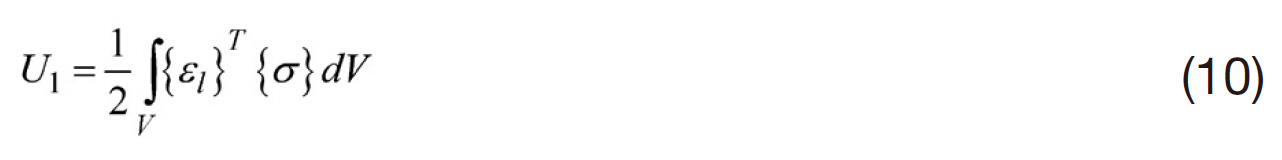
or
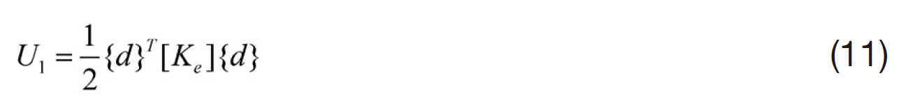
Here [Ke] is called the system elastic stiffness matrix of the entire plate/shell panel.
Strain energy due to non-linear strains
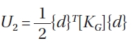
The strain energy U2 due to non-linear strains in the entire plate/shell panel can be expressed in terms of the initial inplane stresses and non-linear strains as given below.
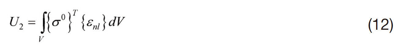
Substituting Eq. (6) in the above, we get
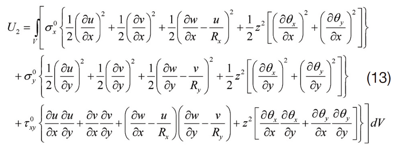
or
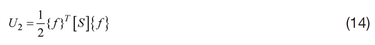
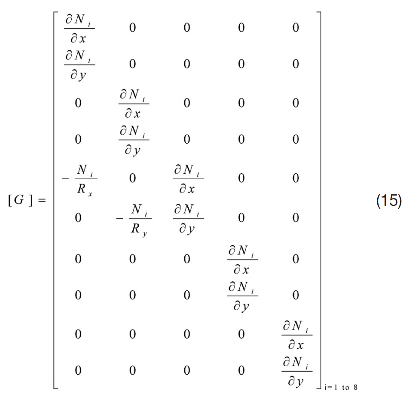
in which
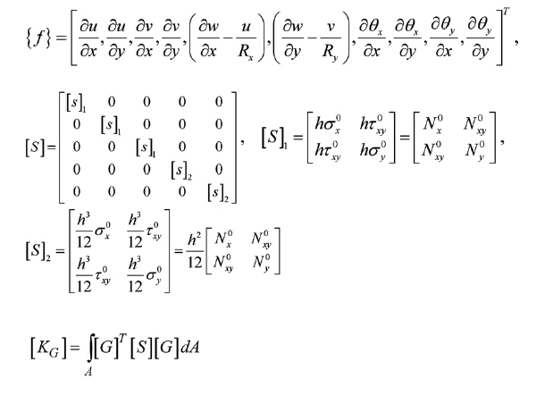
where
or
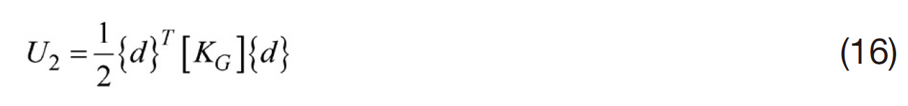
in which [KG] is called the geometric or stress stiffness matrix.
Kinetic energy
The expression for kinetic energy is written in abbreviated form as:
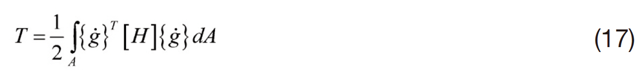
in which,
Work done by the follower force
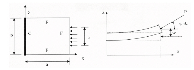
A typical cantilever panel subjected to follower loading is shown in Fig. .10The panel is subjected to partially
distributed compressive follower loading at the free edge such that the load always maintains a direction
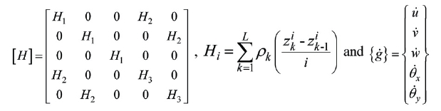
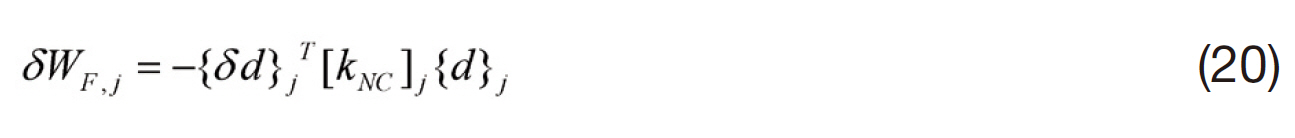
In general, variational work done by the nonconservative forces δWNC consists of two parts: due to follower forces, δWF, and due to damping forces, δWD. Considering the follower forces acting at all the nodes, the variational work can be written as:
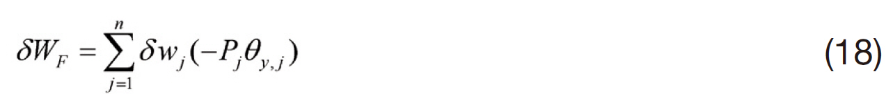
where n is the number of nodes and Pj is the resultant inplane follower force at jth node. The variation of the work done by the normal component of the follower force (?Pjφθy, j),which is normal to the undeformed plane of the panel and acting opposite to the direction of wj for 0.0 < φ < 1.0, at the jth node is expressed as δWF, j = δwj(?Pjφθy, j). This can be written in matrix form as:
or in abbreviated form
in which
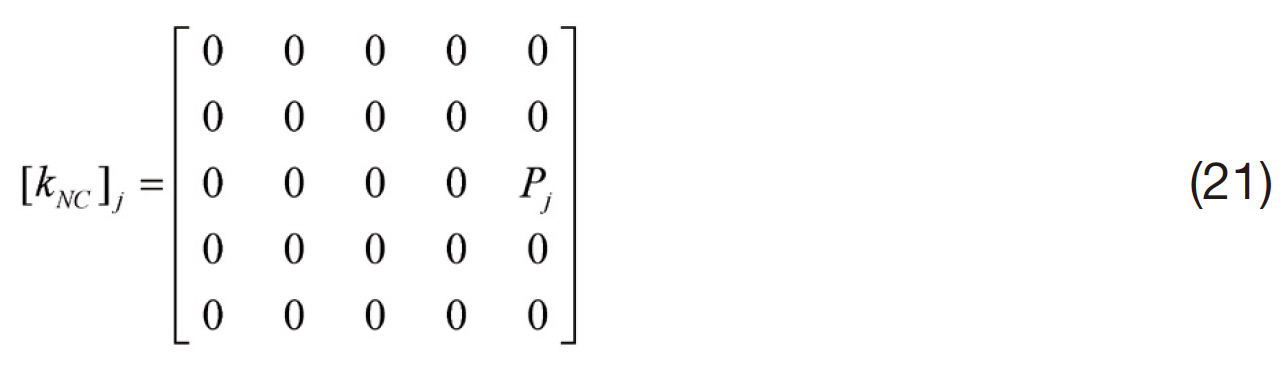
Considering the components of the follower forces at all the nodes, the variation of work can be written in matrix form as:

in which
{d} is the system displacement vector and(

called nonconservative stiffness matrix.
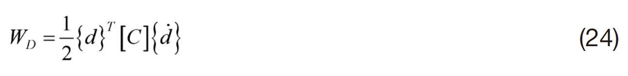
Work done by the damping force
Damping is usually introduced into the structural systems by means of dissipation function. The energy dissipation function in matrix form, consistent with the form of energy expressions for
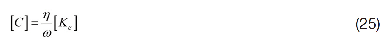
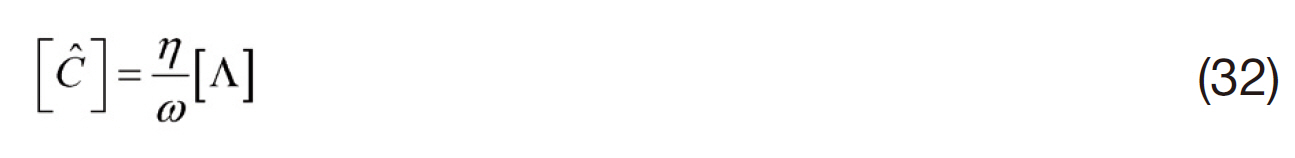
Another form of damping representation is the structural damping expressed as a complex stiffness matrix of the form(1+iη)[Ke], where η is the loss factor. Here, imaginary part of the stiffness matrix, η[Ke] (also called as structural damping matrix) corresponds to the energy dissipation in the system.In the present investigations, results have been obtained using the concept of structural damping.
For sinusoidal motion of the panel, structural damping can be expressed in terms of an equivalent viscous damping matrix as follows
The variation of the work done by the damping forces can be written in matrix form as
3.2.3 Governing differential equation?Hamilton’s principle
The various energies and the work done due to nonconservative forces have been formulated earlier and are summarised here
The strain energy due to linear strains is
The strain energy due to non-linear strains is
The kinetic energy is T = 1/2 {d}T[M][d]
The variational work done by the follower force isδWF = ?{δd}T[KNG]{d}
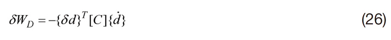
The variational work done by the damping force isδWD = ?{δd}T[C]{d}
The total variational work done by the nonconservative forces is expressed as δWNC = δWF + δWD
It may be noted here that the initial in-plane stresses used in the generation of [KG] matrix is due to some standard inplane components of external static or dynamic follower load and is generally taken equal to unity. Similarly, the sum of the normal components of the Pj in the nonconservative matrix[KNC] will also be unity. Therefore, if the actual load is
The extended Hamilton’s principle can be written as
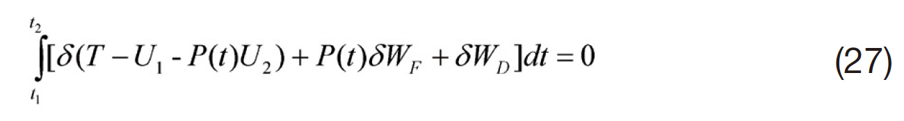
Substituting the above expressions of the energies and expressions of work done in Eq. (27) gives
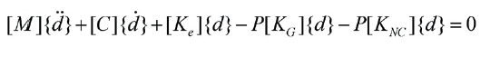
or

The above equation is the most general governing differential equation of motion.
In the above equation, {d} is the nodal displacement vector and P is the magnitude of the applied follower load. The matrix[KG] takes into account of all the in-plane (conservative)component of the applied load, while the matrix [KNC]takes into account of the nonconservative component of the follower load that is in a direction perpendicular to the undeformed mid-plane of the panel. However in the present investigation only edge follower load with certain width as shown in Fig. 10 is considered. Here the load width (
Modal transformation
The orders of the finite element matrices in Eq. (28) are very large and the solution of this equation in its original form may be prohibitive, particularly for determination of the flutter load. Hence a modal transformation is applied to Eq. (28) to reduce its s ize and to retain only the most dominant modes of vibration. The equilibrium equation for free vibration of an undamped unloaded panel can be written as:

where ω is the angular natural frequency of vibration and{q0} corresponds to the mode shape of free vibration. Eq. (29)is solved for the first few modes of vibration by means of a subspace iteration method. Let [Φ] be a modal matrix, which contains the first few normal modes of the free vibration problem Eq. (29), and let

where {ξ} are normal co-ordinates. Substituting Eq. (30)in Eq. (29) and premultiplying by [Φ]T, the following modal equilibrium equation is obtained.
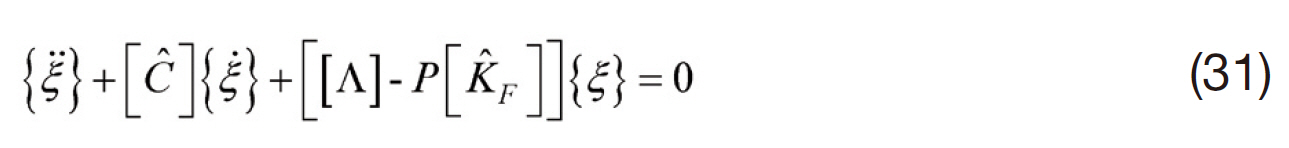
where [?] = [Φ]T[C][Φ] and [□ F] = [Φ]T [[KG] + [KNC]][Φ]; [Λ] is a diagonal matrix containing the eigenvalues of Eq. (29), that is squares of the natural frequencies of free vibration of the unloaded panel.
From Eq. (25),
Now considering the motion of the panel in the form {ξ} ={ξ0}eiwt, Eq. (31) reduces to
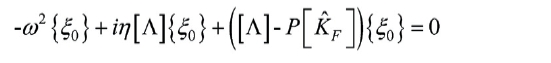
or
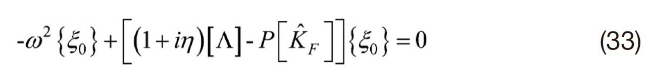
Eq. (33) is an eigenvalue problem with eigenvalues ω2,which are the squares of the natural frequencies of free vibration under follower load P. Eq. (33) can be solved by using standard eigenvalue routine for a complex general matrix. The imaginary part of ω corresponds to the exponential increment or decrement of the amplitude of vibration.
Shell (curved panel) classification
The generalized formulation considers all the radii of curvatures viz. Rxx, Ryy, Rxy. The shell surfaces considered for the present study have the following features and can be handled by the formulation proposed herein as special cases as furnished below.
Spherical shell: doubly curved and synclastic surface having 1/Rxx = 1/Ryy, both positive and 1/Rxy = 0.
Cylindrical shell: singly curved surface having 1/Ryy only, and 1/Rxx = 1/Ryy = 0.
Hyperbolic paraboloidal shell: doubly curved and anticlastic surface having ?1/Rxx = 1/Ryy and 1/Rxy = 0
Using the mathematical and finite element formulations described so far, extensive research investigations were done for isotropic, composite plates/curved panels subjected to the non-uniform follower forces and considering the effects of damping. These papers are reviewed here.
Datta and Deolasi (1996) studied some aspects of dynamic instability characteristics of isotropic plates subjected to partially distributed follower edge loading with damping. It was shown that, under follower loading,the system is susceptible to instability due to flutter alone or due to both flutter and divergence, depending upon the system parameters. The damping in the system is observed to have a destabilizing effect on the flutter behaviour. Ravi Kumar et al. (2003) investigated parametric instability behaviour of laminated composite plates subjected to partial follower edge load with damping. The effects of load width, boundary condition, ply orientation, direction control of load and damping parameters were considered on instability behaviour. In most cases the damping effect gives destabilizing behaviour, making the plate prone to flutter. The effect of direction control parameter significantly affects the critical load depending on the type of ply and the ply orientation. Dynamic instability characteristics of doubly curved isotropic panels under partial follower edge loading with damping were studied by Ravi Kumar et al. (2004a). The damping in the system was observed to have a stabilizing effect on a flat panel. Further, flutter was found to be more complex than divergence for the curved panels. Ravi Kumar et al. (2004c) investigated on the effects of aspect ratio and boundary conditions on the instability of doubly connected panels. The results showed that the effects of shallowness ratio, boundary conditions and aspect ratio are significant on dynamic effects instability characteristics of the panel.It was also observed that structural damping significantly affected the flutter loads of the panels.
Datta (2004) gave a perspective view on the stability characteristics of aerospace structures subjected to nonconservative force systems. Ravi Kumar et al. (2005a)studied vibration and dynamic instability characteristics of laminated composite doubly curved panels, subjected to non-uniform follower load. The in-plane stress distribution in the panel, in general, is a combination of tensile and compression stress zones, leading to stiffening?de-stiffening effect. This behaviour and its effect on instability behaviour was discussed depending on system parameters. Flutter behaviour of laminated composite cylindrical panel subjected to non- uniform follower force was studied by Ravi Kumar et al. (2005c). It was observed that the load bandwidth got significant influence on free vibration, flutter and divergence characteristics of panels having different edge conditions. The type of ply orientation, number of layups and angle of laminate affect significantly the stability behaviour under partially distributed follower edge load.Ravi Kumar et al. (2005d) studied the effects of boundary condition, load direction control parameter and damping for the stability behaviour of cantilever plate under follower load.The effects of non-uniform follower forces and damping on the dynamic instability behaviour of laminated composite plates were studied by Datta et al. (2007). The results showed that under non- uniform follower forces, combination resonance of difference type are as important as simple resonance zones. The effects of damping showed that there is critical value of dynamic load factor for each instability region below which the laminated composite panel cannot become unstable. Deolasi and Datta (1994), investigated on the dynamic instability characteristics of plates subjected to periodically excited partially distributed follower load.The MMS was used for the solution of non-linear oscillation and parametric instability problem. It was observed that combination resonance zones of difference type were significant under pulsating follower load. The significant effects of damping on instability zones were observed.
3.2.2 Plates and curved panels with central cut-out
This section reviews the plates and curved panels with an internal opening subjected to partial follower load.The presence of hole develops a non-uniform stress field comprising of tension-compression zone. In certain domain,when the tensile zone dominates, it gives rise to stiffening effect. On the other hand, domination of compression zone leads to destiffening behaviour. The instability behaviour of such problems is of interest.Fig. 11 describes a panel with internal opening subjected to follower load. Ravi Kumar et al. (2004d) studied on the dynamic instability characteristics of laminated composite plate with circular cut-out subjected to non-uniform follower force. The effect of cut-out size,load bandwidth and load control parameters was found to be significant on the flutter behaviour of the plate. The damping effect showed destabilizing nature on the stability behaviour with cut-outs. Vibration and parametric instability characteristics of isotropic plate with circular hole under partially distributed follower force were investigated by Ravi Kumar et al. (2004e). The effect of boundary condition, load direction control parameter and damping were considered on dynamic instability characteristics. Ravi Kumar et al.(2004b) studied the vibration and dynamic instability behaviour of square isotropic/laminate composite plates with circular hole subjected to partially distributed follower edge forces. The first order shear deformation theory was used to model the plate in FEM formulation, considering the effects of shear deformation and rotary inertia. The effects of cut-out size, load width, boundary condition, ply orientation,direction of load and damping parameters were considered for the stability behaviour of plate.
The instability behaviour of doubly curved panels with circular cut-out subjected to partially distributed follower edge loading was studied by Ravi Kumar et al. (2005b). The effects of cut-out and curvature of the panels influence the dynamic stability behaviour. The magnitude of the flutter load was found to be gradually decreasing with the increasing cut-out size. The curvature of the panels improved the flutter behaviour. In most cases, the damping effect showed destabilizing behaviour making the panel prone to flutter.
3.2.3 Plates and curved panels with internal damage
The papers reviewed so far discussed about nonconservative problems on isotropic/composite plates/panels without any inhomogeneities or damage. However,studies on behaviour of damaged structures are important in aerospace structural analysis. Unlike isotropic materials that are mostly damaged by cracks or undergo a reduction of stiffness due to surface wear are tear, composite materials experience damage in the form of blunt body impact, fibre breakage and delamination. The inhomogeneities may also be improper or erroneous manufacturing techniques.Analysis of such ‘improper’ structures can be carried out by incorporating a suitable damage model in the formulation.These damages or inhomogeneities in the structure are reflected in the spectrum as shift in natural frequencies and instability behaviour of the structure.
Proper representation of damage model is essential in continuum mechanics to formulate the instability problem.Stiffness reduction due to damage can be achieved through various means. While specific problems can be solved by‘hard-wiring’ the damage into the model, a parametric model is more versatile. Valliappan et al. (1990) developed a finite element model of anisotropic damage based on structural stiffness reduction factor.
Mathematical formulation?anisotropic damage
Anisotropic damage can be parametrically incorporated into the formulation by considering the parameter,
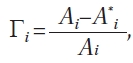
a representation of reduction in effective area, A*i(Valliappan et al., 1990). Using this, the relationship between a damaged stress tensor and an undamaged stress tensor can be obtained as
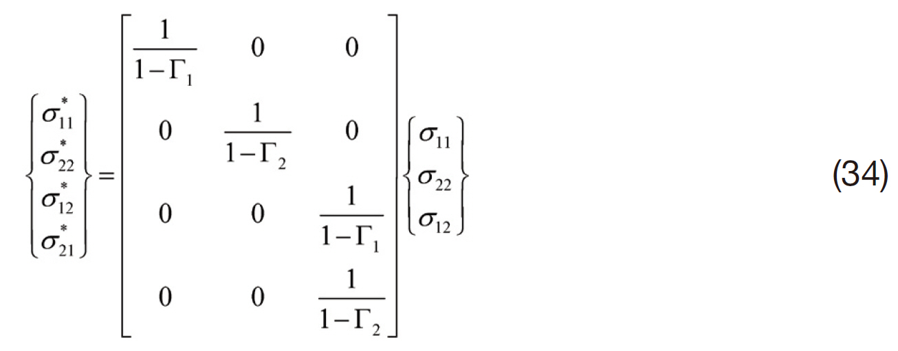
The above equation can be abbreviated as {σ*} = [ψ]{σ},where {ψ} is a transformation matrix and can be used to relate a damaged stress-strain matrix with an undamaged one, [D*]?1 = [ψ]T[D]?1[ψ]. The damaged stress-strain matrix for a two-dimensional laminate can be written as
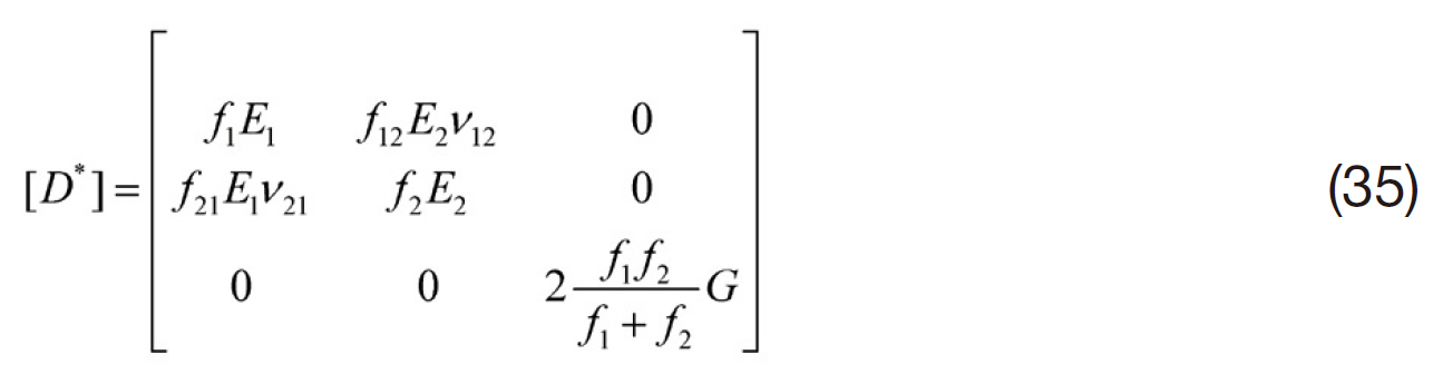
where the factors
and
are defined as stiffness reduction factors.For a damaged region, the stress-strain relation can be written as {σ*} = [D*]{ε}. This relation can then be transformed into the general coordinate system as used in general undamaged cases.
Method of multiple scales
When a pulsating, harmonic load, P(t) = αPcr + βPcr cos(Ωt),expressed in terms of the buckling load, Pcr, is applied to an undamped system and a modal transformation is performed on the system, the transformed differential equation can be written as

where [Λ] = [φ]T([K] ? αPCR[KG][φ] and [□G] = ? PCR[φ]T([KG] [φ].
[KG] is the geometric stiffness matrix, [φ] is the modal matrix containing the first M normal modes of vibration under static component of load, Ps = αPCR. {ξ} is the vector containing the orthogonal modal coordinates. [Λ] is the diagonal matrix containing the squares of first M frequencies of vibration under the static component of loading as the diagonal elements.
Eq. (36) is a form of the Mathew Hill equation, whose component form can be written as
where m, n = 1, 2, 3, …, M
The terms containing ε and Ω and couples the dynamic load to the normal modes of the system, due to which a perturbation method called MMS (Nayfeh and Mook, 1979)is used to solve the system of equations. The ‘nearness’of Ω to the sum of ωm and ωn for sum type of combination resonance can be represented by introducing a small detuning parameter, σ, such that Ω = ωm + ωn + εσ. For a second order expansion, the values of σ are obtained from the roots of a second order polynomial (Deolasi and Datta,1997; Udar and Datta, 2006) and are given by
where
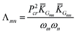
and
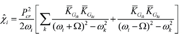
When m = n, the Eq. (38) predicts simple resonance zones,while for m ≠ n, combination resonance zones are obtained.
Datta et al. (2009a) studied dynamic behaviour of laminated composite plate with flaws under non-uniform follower forces. The results showed that the introduction of damage influence the flutter characteristics of the plate more profoundly than free vibration or buckling characteristics.Dynamic instability characteristics of composite curved panels with internal damage subjected to follower forces were investigated by Datta et al. (2009b). The results indicated that, compared to undamaged panels, heavily damaged panels show steeper deviations in stability characteristics than mildly damaged ones. Datta et al. (2010) studied the vibration and flutter behaviour of laminated composite panels with flaws under follower force. Static and dynamic instability characteristics of curved laminates with internal damage subjected to follower loading were studied by Biswas et al. (2011).
It was observed that the introduction of curvatures in the panel have increased fundamental natural frequency,critical buckling load and dynamic instability characteristics(flutter load and flutter frequency) in comparison to the corresponding flat plates. In general, flutter load decreased with the increase in damage ratio. An increase in damage ratio reduced the flutter load.
This paper has reviewed the aeroelastic behaviour of aerospace structural elements such as column, plate and curved panel subjected to nonconservative follower type of forces. One dimensional structure such as beams and columns idealize missile structure subjected to end rocket thrust. On the other hand, two dimensional plate/curved panel types of structures resemble wing of an aircraft subjected to follower forces (engine thrust) or distributed partial load over a region. Because of flexible nature of these structures, the follower forces change the directions(known as tangency parameter) and the structures undergo static instability (divergence) or dynamic instability (flutter),giving rise to unbounded deformation or growth of vibration without bound.
The instability phenomena discussed above depend on system parameters. These effects as discussed in the literature have been reviewed here. The damping in the system is an important parameter. The damping in most cases was observed to have a destabilizing effect on flutter behaviour.The static and dynamic instability phenomena of laminated composite panel are of special interest. The effect of load direction control parameter significantly influenced critical load depending on the type of ply and the ply orientation.
Plates and curved panels having discontinuities such as damage and openings cannot be avoided in aerospace structure. The present review paper has discussed the instability problems due to the presence of discontinuities in a highly non-uniform stress field comprising of tension?compression zone. It was observed that the stiffeningdestiffening behaviour of the panels influence the instability behaviour.