Fiber reinforced polymer composites (FRPs) possess high specific moduli and specific strengths and are widely used in many structural applications including aerospace, sporting goods, automobile, civil and marine structures. While the inplane and fiber dominant properties make these composites useful in these applications, their through-the-thickness properties are limited by the relatively poor properties of the matrix resin and the weak fiber-matrix interfacial bond. In order for FRPs to offer better choice for aerospace and military components over monolithic metallic structures possessing no delamination problems, significant improvements in the through-the-thickness properties are necessary.
It is well known that composite structures in the form of laminates are extremely susceptible to crack initiation and propagation along the laminar interfaces in various failure modes. In fact, delamination is one of the most prevalent life-limiting crack growth modes in laminate composites as delamination may cause severe reductions in in-plane strength and stiffness, leading to catastrophic failure of the whole structure (Kim and Mai, 1998). Delamination may be introduced by external loading as in static bending,compression or tension, in cyclic fatigue or by impacts of low-to-high energies, during manufacturing or in service.Impact loading during service is a common phenomenon for aerospace composite structures. There are situations like tool drops, runway debris, bird strikes, hailstorms and ballistic strikes, which induce considerable damage to the composite. In order to produce an impact resistant structure, it is important to understand the dynamics of the impact event and thus to predict the extent of the induced damage and estimate the residual properties so that the composites are designed with improved structural integrity and mechanical performance after impact (Kim, 1998; Kim and Sham, 2000).
Many useful techniques have been successfully devised to improve the delamination resistance in the past three decades, namely three-dimensional (3D)-weaving (Mouritz et al., 1999; Tong et al., 2002), stitching (Dransfield et al., 1994;Dransfield et al., 1998; Reeder, 1995), braiding (Brown and Crow, 1992), embroidery (Tong et al., 2002), Z-pin anchoring (Abe et al., 2003; Mouritz, 2007), fiber hybridization,toughening the matrix resin (Reeder, 1995) and interleaving with tough polymer, short fibers or microscale particles (Hojo et al., 2006a, b; Kim et al., 1992; Liao et al., 1994; Singh and Partridge, 1995). These methods enhanced the interlaminar properties but at the cost of in-plane mechanical properties(Chang et al., 2007; Dickinson et al., 1999; Reeder, 1995;Steeves and Fleck, 2006).
In addition to the resistance to interlaminar fracture and impact damage, FRPs for advanced aerospace structures often require the most demanding multi-functional properties. The introduction of nanotechnology in the field of composite materials with nanoscale fillers, such as carbon nanotubes (CNTs) and carbon nanofibers (CNFs),has offered new opportunities to improve these mechanical and multifunctional properties of FRPs (Khan et al., 2011b).In light of their excellent Young’s modulus and strength,extremely high aspect ratio, large surface area, and excellent thermal and electrical properties, these nanofillers can be incorporated into the FRPs to modify the properties of polymer matrix (Tsantzalis et al., 2007). Apart from CNTs and CNFs, other types of nanofillers have been extensively studied as additives for polymer composites, such as layered silicates(Iqbal et al., 2009; Khan et al., 2010, 2011a; Siddiqui et al.,2007), metal oxide nanoparticles (Nussbaumer et al., 2006;Rojas-Chapana and Giersig, 2006), inorganic nanotubes(Rao et al., 2003), expandable graphite nanoplatelets or graphene (Li and Kim, 2007; Wang et al., 2010), layered titanate (Hiroi et al., 2004), cellulose nanowhiskers (Choi et al., 2005; Mohanty et al., 2003) and polyhedral oligomeric silsesquioxanes (Joshi and Butola, 2004).
This paper aims to provide an overview of the enhancement of mechanical properties of FRPs, especially the impact and delamination resistance, arising from the incorporation of CNTs and CNFs in the composites.Discussed are the special techniques employed to securely integrate these nanofillers into the composites so as to avoid agglomeration while maximizing their effects on improving the interlaminar fracture resistance. A particular focus is placed on understanding the physical and mechanical interactions between the nanofillers and the microscale fiber reinforcements, as well as the underlying mechanisms of property improvements of the multiscale composites.
1.1 CNTs and CNT-polymer nanocomposites
The discovery of multi-walled CNTs (MWCNTs) produced by the arc evaporation of graphite in an inert atmosphere of helium has attracted tremendous scientific and technological interests in the last two decades (Iijima, 1991). Depending on the processes used for CNT fabrication, there are two types of CNTs: single-walled CNTs (SWCNTs) and MWCNTs.SWCNTs consist of a single graphene layer rolled up into a seamless cylinder whereas MWCNTs consist of two or more concentric cylindrical shells of graphene sheets coaxially arranged around a central hollow core with van der Waals forces between the adjacent layers. SWCNT can be further divided into three classes, i.e. armchair, zigzag and chiral types, depending on the arrangement of hexagons in their structures (Bethune et al., 1993; Ma et al., 2010; Tjong,2006).
Following the first report on the preparation of a CNT/polymer nanocomposite in 1994 (Ajayan et al., 1994), a myriad of research efforts have been made to understand their structure?property relationship and find useful applications in emerging fields. CNTs have been recognized as a potential candidate for the reinforcement of polymeric materials due to their many excellent physical, mechanical and functional properties, and extremely high aspect ratios. Depending on the area of applications, CNT/polymer nanocomposites can be classified into structural and functional composites(Du et al., 2007). For structural composites, much improved mechanical properties are explored based on the high modulus, tensile strength and strain to fracture, and excellent damping characteristics of CNTs. For functional composites,unique properties of CNTs, such as excellent electrical and thermal conductivities and opto-electronic properties, along with their mechanical properties are utilized to develop multi-functional composites for applications in the fields of heat resistance, chemical sensing, electrical and thermal management, photoemission, electromagnetic absorbing and energy storage devices, etc. (Ma et al., 2010).
However, the measured mechanical properties of CNT composites are often found far below their theoretically predicted potentials, due to many issues associated with lack of uniform dispersion, random nature of the CNT dispersion,breakage of CNTs during processing and weak interfacial interaction with polymer. Among the major concerns are i) the difficulty in dispersion of CNT agglomerates into the individual CNTs in the polymer matrix due to their strong van der Waals interactions and ii) the lack of adhesion between the CNTs and the polymer matrix. Various techniques have been developed to address these problems, and recent work(Ma and Kim, 2011; Ma et al., 2010) provides comprehensive reviews on dispersion and functionalization of CNTs for polymer-based nanocomposites.
1.2 Integration of CNTs in fiber reinforced composites
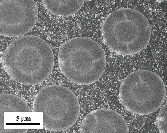
The exploitation of various unique properties of CNTs in a composite depends strongly on how the CNTs are integrated into the three-phase multiscale composites.The incorporation of nanoscale CNTs with conventional microscale fiber reinforcements in a common polymer matrix can be achieved by modifying either i) the matrix resin or ii) the fiber reinforcement using the CNTs. Modifying the matrix resin by dispersing CNTs in the polymer offers the most conventional, facile and industrially compatible route. A typical scanning electron microscope (SEM)image of the three-phase CNT-carbon fiber FRP (CFRP)multiscale composite fabricated by modifying the matrix resin with CNTs is presented in Fig. 1 (Yokozeki et al., 2007).A number of different techniques have been developed for CNT dispersion into a polymer matrix, which includes shear mixing, calendaring, extrusion, ultrasonication and ball milling (Ma et al., 2010). Many of the recent studies are often based on the use of a combination of aforementioned techniques, such as ultrasonication plus ball milling (Ma et al., 2009), and ultrasonication plus extrusion (Isayev et al.,2009; Moniruzzaman et al., 2006). Fabrication of multiscale FRPs using modified resins has some limitations that hinder their development and widespread applications. One of the main problems in this approach is that the viscosity of a CNT-modified matrix increases dramatically with increasing CNT content, even with a very small content below 1 wt%,leading to severe agglomeration of CNTs in the bulk of the composite. The highly viscous and CNT-agglomerated resin systems cannot be processed using the conventional composite manufacturing techniques. For example, when fabricating multiscale FRPs using the vacuum assisted resin transfer molding (VARTM) process, nanofillers can become filtered, resulting in an inhomogeneous microstructure of multiscale composites (Fan and Advani, 2005; Green et al., 2009; Qiu et al., 2007; Sadeghian et al., 2006). Filtering is caused by the nanofillers being trapped in inter-tow regions within the fiber preform mesh during fabrication.A comprehensive study (Sadeghian et al., 2006) revealed a direct correlation between the concentration of CNFs and
the processing parameters, such as viscosity and filtering:a CNF concentration above 1% resulted in a significant filtering effect, leading to the formation of many microvoids in the composite.
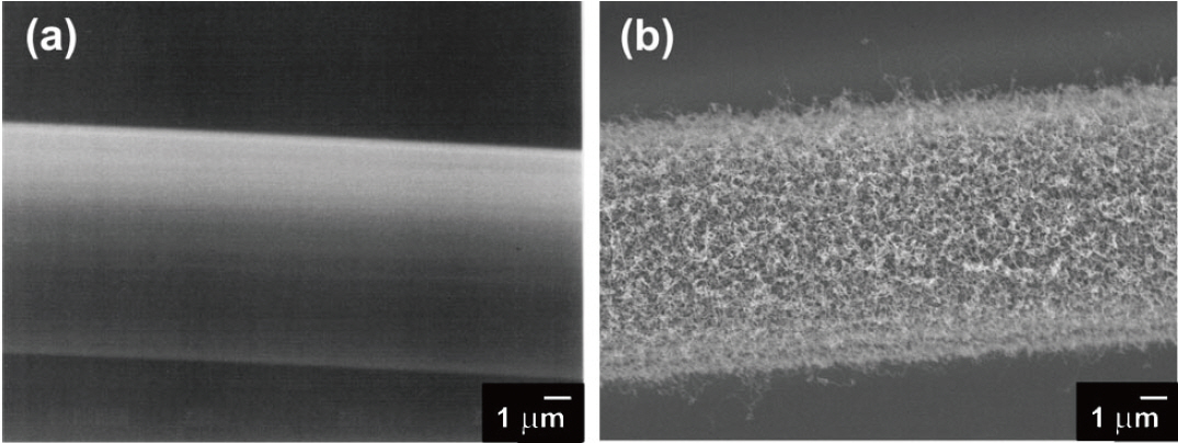
Apart from the above conventional techniques of mixing CNTs with a polymer resin before incorporation with fiber reinforcements, more systematic approaches have been developed to fabricate advanced FRPs, including i)attachment, grafting or growth of CNTs on the reinforcing fibers or fabrics, ii) interleaving bucky papers made from CNTs at certain laminar interfaces, iii) manual spreading or spraying of CNTs on prepregs. The key advantages of direct attachment of CNTs on the fibers/fabrics or interleaving technique are the ability to incorporate CNTs at high concentrations and incorporate the CNTs selectively at the locations of interest within a composite. Thostenson et al.(2002) were the first group of researchers who successfully synthesized CNTs via chemical vapor deposition (CVD) on the surface of carbon fibers as shown in Fig. 2. The effects of growth conditions on CNT morphology have been evaluated in the subsequent studies (Cesano et al., 2005;Hung et al., 2008; Yamamoto et al., 2009; Zhu et al., 2003).Grafting of aligned CNTs or CNFs on to the conventional fiber surface resulted in a 3D hierarchical composite (Fig. 3)with enhanced mechanical and multifunctional properties(Veedu et al., 2006). Downs and Baker (1995) reported an increase by about 300 times in fiber surface area after the growth of CNFs, a much greater effect than typically obtained with conventional roughening treatments (Donnet et al., 1998) which offered increases of less than a factor of 10.They also demonstrated an increase of 4.8 times in interfacial shear strength of the composite containing CNF-grafted carbon fibers (Downs and Baker, 1995).
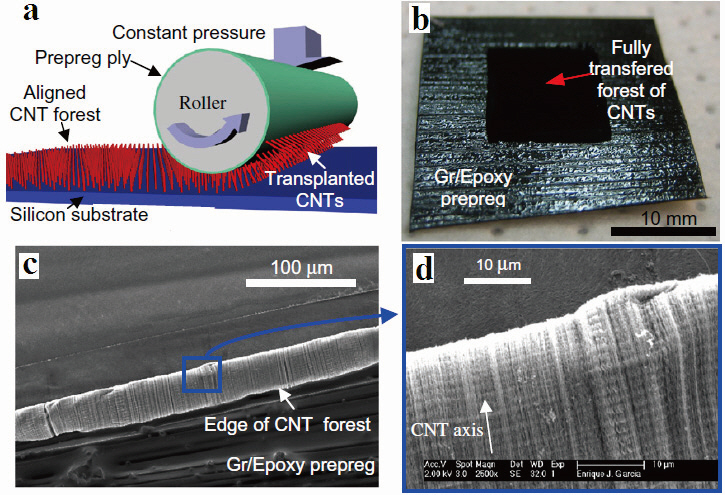
Garcia et al. (2008a) introduced aligned CNTs to CFRPs.This was accomplished by growing a vertically-aligned CNT forest at a high temperature, and then transfer-printing the CNTs to prepregs at room temperature. The prepreg was attached to a cylindrical drum that was rolling under pressure
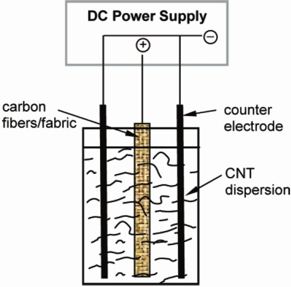
across the substrate containing the CNT forest to transfer the CNTs to prepregs, taking advantage of the tack of the prepregs to separate the CNT forest from the growth substrate (Fig.4). Electrophoretic deposition (EPD) is another technique that has been widely applied to selectively deposit CNTs on fabrics as shown in Fig. 5. CNTs were uniformly deposited on the surface of carbon fabrics using the EPD technique where both as-received and oxidized CNTs were deposited onto the carbon fiber electrodes under an applied electric field (Bekyarova et al., 2007). EPD is a simple and versatile technique that can be readily automated and scaled up for mass production.
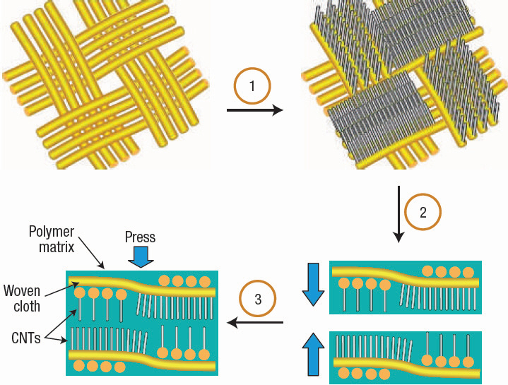
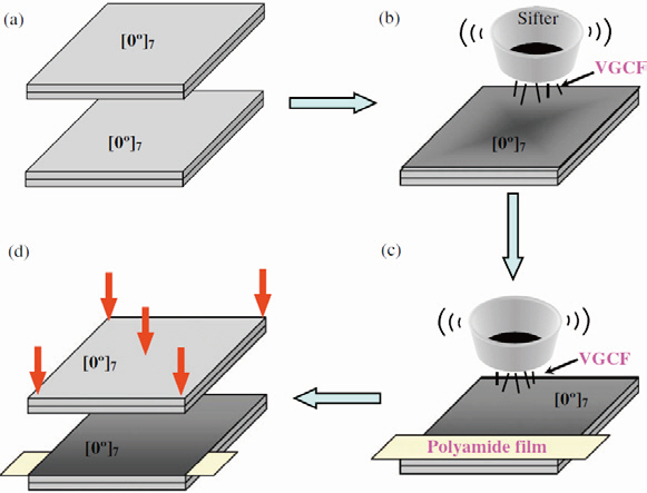
A technique known as ‘powder method’ was devised to add CNTs onto the ply surface (Li et al., 2009). The method is schematically described in Fig. 6 where the powder of
vapor grown carbon fibers (VGCFs) are manually spread at the mid-plane of CFRP laminates using a sifter with a mesh size about 70 μm. A VGCF interlayer is automatically formed during melting and curing of resin at a high temperature and pressure in the autoclave. A CNT-solvent paste, e.g. CNFethanol past, was also applied manually on a CFRP prepreg using a metal roller (Arai et al., 2008). After evaporating the solvent on the prepreg sheets, the two parts of prepregs were bonded together and cured. A CNF interlayer of 50-200 μm in thickness was naturally formed by the fusion of CNFs and epoxy resin during curing. A thin layer of CNTs was also dispersed onto the surface of woven fabric using a spray-up process (Zhu et al., 2007). This process involved coating of a pre-dispersed CNT-solvent solution on the fabric using a spray gun, and deposition of CNTs at the prescribed weight percentage on the fabric after evaporation of the solvent.Composites were then produced through a RTM process.CNTs were also integrated into FRPs by adding CNTs in the fiber sizing formulation through which the continuous fibers were drawn (Warrier et al., 2010).
Interleaves containing well-dispersed CNTs in a β-stage epoxy thin film were developed to insert between plies in a laminate composite, which was subsequently co-cured with the infused epoxy resin based on a VARTM process (Sun et al.,2010). The interleaving thin films were produced by dispersing CNTs in epoxy after sonication and casting on a release paper using a thin film coater. This technique is limited to low CNT contents because the films are produced by dispersing CNTs in a resin using a conventional method. However, the CNT contents in the interleaves can be drastically increased if CNT bucky papers are employed. Composite thin films have recently been produced using partially cured epoxy-CNF bucky papers of high CNF contents for use as interleaves in CFRPs (Khan and Kim, 2011), where the CNF bucky paper was impregnated with an epoxy resin by vacuum infiltration.The partially cured composite thin film was placed between CFRP prepregs before curing to improve the interlaminar fracture resistance of the bulk composites. This approach allowed the incorporation of high CNT contents in FRPs,avoiding the difficulties associated with high viscosity arising from the high nanofiller contents.
The choice and application of the aforementioned techniques for integration of CNTs and CNFs in FRPs depend on many factors, including the availability of required tools or equipment, CNT contents and the final composite properties being sought. The mechanical and fracture performances of the resultant FRPs containing nanofillers are discussed in the next section.
2. Interlaminar Failure in Multiscale CNT-FRP Composites
The mechanical and structural performance of a FRP depends on the fracture resistance to various modes of crack
[Table 1.] ILSS of CNT-fiber multiscale composites
ILSS of CNT-fiber multiscale composites
propagation. Since one of the most critical design criteria for FRPs for structural applications is their sufficient fracture energy absorption capability, there have been a number of attempts to improve the fracture toughness (Karapappas et al., 2009; Kim, 1998; Kim and Mai, 1998). One key area where nanofillers such as CNTs and CNFs can make a significant impact is to address the interlaminar properties of FRPs.
A number of publications have demonstrated that the addition of CNTs in a polymer matrix can increase the toughness of the bulk matrix as well as the interface properties of CNT-polymer nanocomposites (Du et al., 2007;Spitalsky et al., 2010; Thostenson et al., 2001). For example,Gojny et al. (2005b) demonstrated a 43% increase in fracture toughness of epoxy resin with 0.5 wt% amine-functionalized double-walled CNTs (DWCNTs), whereas Ganguli et al.(2005) studied the effect of MWCNTs on fracture toughness of a tetrafunctional epoxy resin showing a three-fold increase in stress intensity factor with 1 wt% CNTs. A number of other studies also showed moderate to significant improvements in fracture toughness of polymer nanocomposites with small CNT contents often less than 1 wt% (Fiedler et al., 2006;Gryshchuk et al., 2006; Ma et al., 2007). These promising results opened a new avenue to use CNTs in modifying the properties of FRPs that are dominated by the inherent properties of the matrix material.
2.1 Interlaminar shear strength
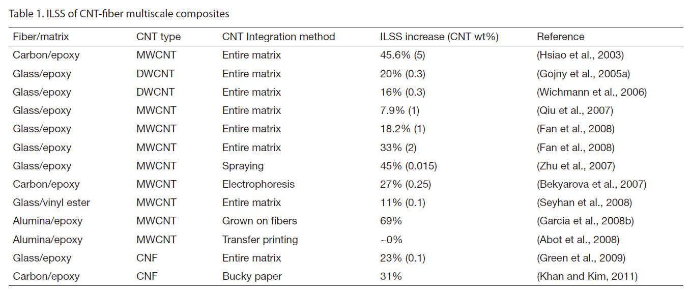
Table 1 presents a summary of the published data on interlaminar shear strength (ILSS) of multiscale CNTFRP composites. The non-crimp glass FRPs (GFRPs)manufactured by an RTM technique exhibited a 20%improvement in ILSS with the addition of 0.3 wt% amino-functionalized DWCNTs (Gojny et al., 2005a). Both the Increased strength of the epoxy matrix and the fibermatrix interfacial adhesion due to the functionalized CNTs containing amino-functional groups were responsible for the enhanced ILSS of the GFRPs. A similar finding was also reported later (Wichmann et al., 2006) in that the ILSS of GFRPs was improved by 16% by modifying the matrix material with 0.3 wt% of DWCNTs. However, the interlaminar fracture toughness of the composites was little affected despite the pronounced increase in matrix toughness.
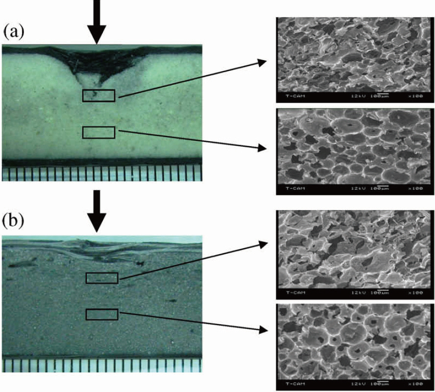
The interfacial shear strength of CNT-reinforced composites was evaluated using the single shear-lap test(Hsiao et al., 2003; Meguid and Sun, 2004). The reinforced adhesives consisting of MWCNTs dispersed in an epoxy resin were used to bond the carbon fiber/epoxy composites adherends (Hsiao et al., 2003), and the results indicated about 46% increase in average shear strength due to the addition of 5 wt% MWCNT into the epoxy adhesive. As shown in Fig. 7,the MWCNTs enhanced the load transfer to the carbon fibers in the adherends so that the failure occurred preferentially in the CFRP composite rather than along the adhesivecomposite interface, see Fig.7a. On the other hand, for the neat epoxy adhesives without MWCNTs (Fig.7b), the failure occurred along the adhesive-composite interface and no significant carbon fiber fracture was observed.
An infusion-based VARTM technique was developed(Qiu et al., 2007) to manufacture multiscale composites where nanocomposites containing strong acid--a mixture of nitric and sulfuric acid--functionalized MWCNTs and epoxy(EPON 862) resin was infused into the glass fabrics in the thickness direction. The ILSS of the multiscale composites was improved by 7.9% and the shear modulus by about 11.7%with only 1 wt% MWCNTs, while the corresponding tensile strength and Young’s modulus were improved by 27.2%and 15.9%, respectively. The functionalization of MWCNTs facilitated uniform dispersion of CNTs and strengthened the CNT-matrix interfacial interactions, allowing improvements
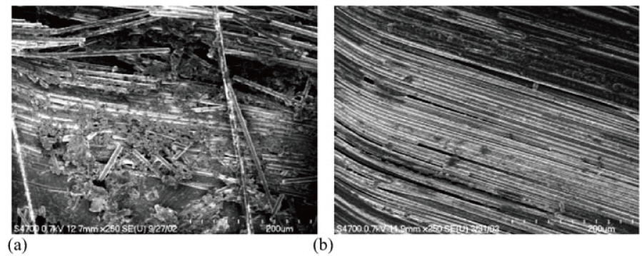
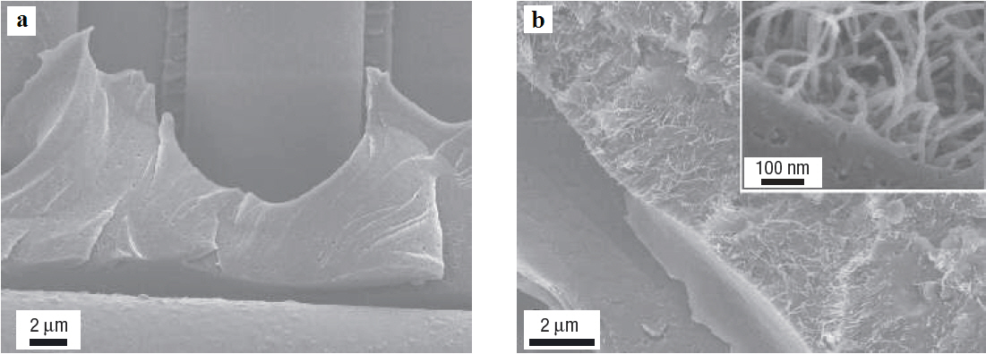
in mechanical properties of the composites. Similarly, the injection and double VARTM (IDVARTM) technique was used to inject MWCNT/epoxy suspensions into the glass fiber mats in the thickness direction (Fan et al., 2008). The ILSS of the composites was characterized using the short beam shear and compression shear tests, showing up to 33%increase in ILSS due to 2 wt% MWCNTs. The preferential orientation of the MWCNTs in the thickness direction was found to contribute to the increase in the interlaminar shear properties. Woven glass fabrics were coated with nanotube-solvent suspension using a spray gun and glass fiber reinforced vinyl ester composites were fabricated using the VARTM process (Zhu et al., 2007). Coating the mid- ply of GFRPs with a small amount of SWCNTs (0.015 wt%) and processing modification led to a remarkable enhancement of ILSS by 45% over the neat composites. The fracture surface morphology of the composites without CNTs showed the matrix completely detaching from the fiber surfaces due to weak adhesion as evidenced by the smooth and clean fiber surfaces (Fig.8 ). In sharp comparison, the composites with CNTs showed a thin layer of matrix covering the fiber surface, a reflection of the failure caused predominantly by resin cracking and deformation within the matrix, suggesting strong fiber/matrix interfacial adhesion. The EPD technique was used to deposit MWCNTs onto the woven carbon fabrics which were subsequently infiltrated with an epoxy resin using VARTM to fabricate composites (Bekyarova et al., 2007). The resultant composites containing 0.25 wt% of MWCNTs demonstrated an enhancement of ILSS by 27%without altering the in-plain mechanical properties, such as tensile strength and modulus.
The growth of aligned CNTs on alumina woven fabrics by CVD increased the ILSS of the epoxy-based composites by 69% (Garcia et al., 2008b). Similarly, aligned CNT forests were grown on a silicon substrate, which were
then transferred to a pre-impregnated carbon woven fabric without buckling or damaging the CNTs (Abot et al.,2008). About 87% improvement in shear modulus of the composites containing aligned CNT forests was reported over the neat composites while the strengths of both composites remained similar. The increase in shear modulus was attributed to the reinforcement effect of the CNTs that prevented an early sliding of the polymer phase. In the subsequent study, multiscale CFRPs were prepared using different types of CNTs (Godara et al., 2009). The results indicated a consistent reduction in ILSS for all composites containing 0.5 wt% CNTs regardless of whether they were pristine, thin or amino-functionalized. The reduction in ILSS for the composites with non-functionalized MWCNTs was expected due to poor interfacial interaction. However, even the amine-functionalized DWCNTs exhibited a significant decrease in ILSS. They concluded that the reduced aspect ratio of DWCNTs, and other factors such as the time and temperature used for functionalization and the high matrix rigidity were responsible for the property reduction.
Khan and Kim (2011) studied the effects of partially cured epoxy-CNF bucky paper interleaves containing 10 wt%CNF on the mechanical properties of CFRP composites.The ILSS of the multiscale composites having CNF bucky paper interleaves was increased by about 31%. The fracture surface analysis revealed that the interlaminar region was reinforced by the randomly-oriented network of CNFs with improvements in both the matrix shear properties and the fiber/matrix interfacial adhesion, which were accountable for the improved ILSS. In a recent study (Chandrasekaran et al., 2010), the effects of various factors, such as processing parameters, manufacturing techniques and batch-to-batch variability of materials, were evaluated on ILSS of multiscale GFRP composites containing MWCNTs. Based on the extensive experimental work, it was hypothesized that the variation in the ILSS enhancement reported in the literature from 0 to 27% can be attributed in part to different types of raw materials and manufacturing processes used to produce the multiscale composites.
2.2 Interlaminar fracture toughness
Tables 2 and 3 present summaries of literature reports
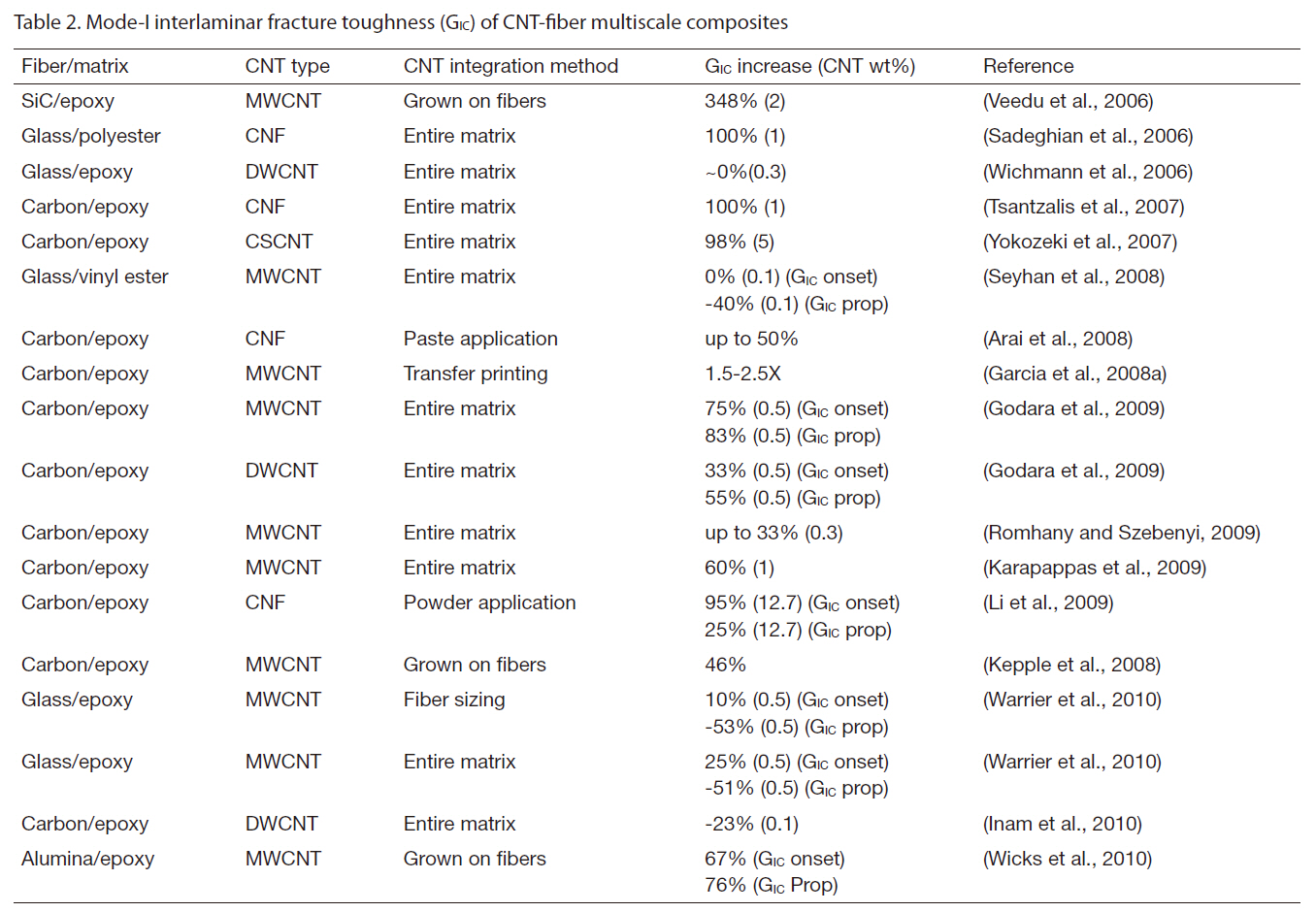
[Table 2.] Mode-I interlaminar fracture toughness (GIC) of CNT-fiber multiscale composites

Mode-I interlaminar fracture toughness (GIC) of CNT-fiber multiscale composites
[Table 3.] Mode-II interlaminar fracture toughness (GIIC) of CNT-fiber multiscale composites
Mode-II interlaminar fracture toughness (GIIC) of CNT-fiber multiscale composites
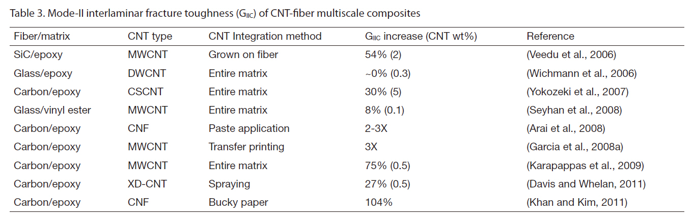
on mode-I and mode-II interlaminar fracture toughness of CNT-fiber multiscale composites, respectively. Most of these studies showed positive results from the incorporation of CNTs in FRPs, ranging from moderate to very large improvements in interlaminar fracture toughness, irrespective of how CNTs were integrated into the composites.
Surfactant-treated CNFs were dispersed in a polyester resin, which was infused to impregnate glass fiber preforms using the VARTM process (Sadeghian et al., 2006). The mode-I delamination tests showed about 100% improvement in GIC of the composites due to 1 wt% CNFs, suggesting CNFs effectively bridging the glass fiber laminae in the thickness direction. A similar increase of 100% in mode-I interlaminar fracture energy of CFRP laminates was achieved with the addition of 1 wt% CNFs (Tsantzalis et al., 2007). The enhancement was attributed to fiber bridging and fiber pullout mechanisms arising from CNFs.
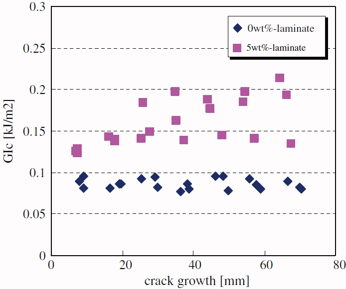
Increases in mode-I and mode-II interlaminar fracture toughness of CFRPs by 98% and 30%, respectively, were reported by adding 5 wt% cup-stacked CNTs (CSCNTs) in an epoxy matrix (Yokozeki et al., 2007). The CSCNT-fiber multiscale composites presented a typical crack growth resistance curve, i.e. R-curve, a reflection of the gradual increase in fracture toughness with crack growth, whereas the CFRP composites without CNTs presented flat fracture toughness regardless of crack length, as shown in Fig. 9. It was suggested that the increase in fracture surface area due to crack deflection in CSCNT-dispersed epoxy was the main contribution to the improved fracture toughness. In a similar study, the CFRP composites made from carbon fiberepoxy prepregs and MWCNTs presented improvements in both mode-I and mode-II interlaminar fracture toughness values by 60% with 1 wt% CNTs and 75% with 0.5 wt% CNTs,respectively (Karapappas et al., 2009). The enhancement was attributed to CNT bridging and pull-out mechanisms that
required extra energy, in addition to the inherent fracture energies, needed for crack initiation and propagation.
More sophisticated techniques have been devised to apply nanofillers at the laminar interfaces of fiber composites and thus to improve the interlaminar fracture toughness: CNTpowder(Li et al., 2009), CNT-solvent paste (Arai et al., 2008),CNT-solvent suspension (Davis and Whelan, 2011), CNFbucky paper (Khan and Kim, 2011), direct growth of CNT/CNF on reinforcement fibers/cloth (Kepple et al., 2008;Veedu et al., 2006; Wicks et al., 2010) and EPD (Bekyarova et al., 2007) have been extensively studies. Manual spreading of nanofillers, such as VGCFs at the mid-plane of CFRP laminates using a sifter has also achieved a decent increase in mode-I interlaminar fracture resistance (Li et al., 2009).Use of CNF-solvent paste, instead of manual spreading, at the delamination-prone surfaces showed remarkable 50%and 2-3 fold increases in mode-I and mode-II interlaminar fracture toughness, respectively (Arai et al., 2008). The integration of partially cured CNF-epoxy bucky paper interleaf at the mid-plane of CFRP laminates demonstrated a significant improvement of 104% in mode-II interlaminar
fracture toughness (Khan and Kim, 2011). The enhancement was attributed to CNF pullout and bridging mechanisms on the microscopic scale, as well as crack deflection and meandering on the macroscopic scale.
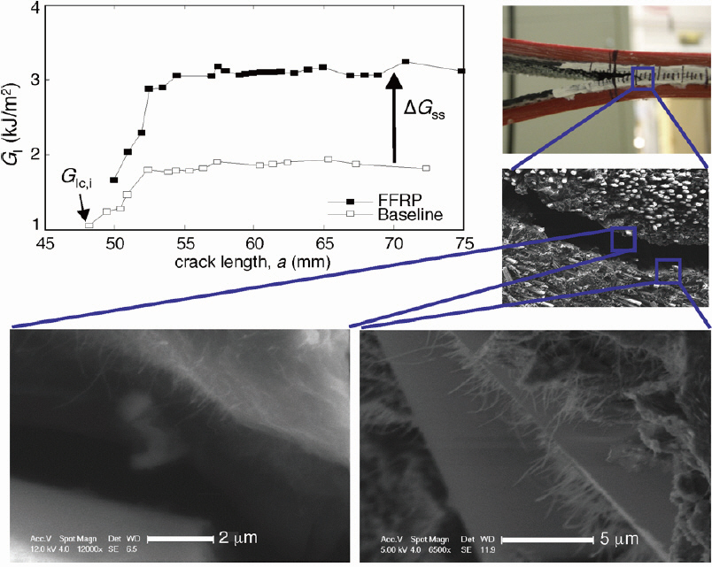
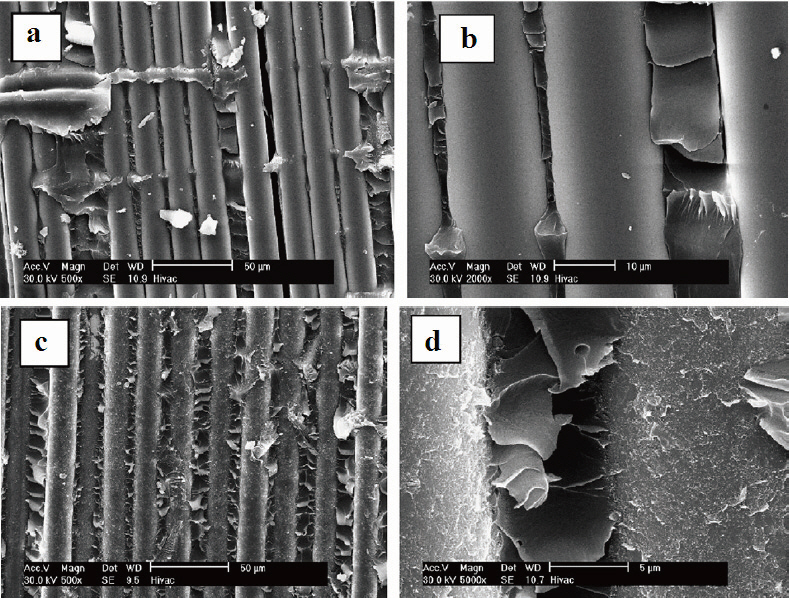
Direct growth of nanofillers on the main reinforcement surface offered a more systematic control of various properties of FRP composites. For example, the mechanical properties, including delamination resistance, hardness and vibration damping capability, were significantly improved by growing CNTs on the surface of silicon carbide(SiC) cloth plies (Veedu et al., 2006). A remarkable 348%improvement in mode-I fracture toughness was achieved without compromising the in-plane mechanical properties.Examination of the fracture surfaces, as shown in Fig. 10, revealed mechanical interlocking between the fibers and the matrix in the composites containing CNTs grown SiC cloth. Interlocking occurred between the adjacent plies due to the CNT forests (see inset in Fig.10), making it difficult to open the plies and thus enhancing the interlaminar fracture toughness. A similar study was made to grow aligned CNTs on the surface of alumina woven cloth (Wicks et al., 2010), which served as 3D reinforcement and improved the mode-I interlaminar fracture toughness by 67% for crack initiation and 76% for steady-state crack propagation, as shown in Fig. 11. The CNT pull-out was the main toughening mechanism and a theoretical model was presented based on the observed CNT pull-out lengths to predict the amount of toughening,showing an agreement with the experimental data.
Despite the aforementioned moderate to very large improvements in interlaminar fracture toughness due to CNT incorporation in FRP composites, a few negative effects have also been reported. For example, GFRPs consisting of 0.1 wt% amino-functionalized MWCNTs and vinyl ester resin were prepared via the VARTM process (Seyhan et al., 2008).Results revealed that there was no beneficial effect of CNT addition on mode-I initiation fracture toughness, whereas the propagation fracture toughness was adversely affected,
with almost 40% reduction, by the CNT reinforcement. It was suspected that the presence of CNTs suppressed fiber bridging. However, it is interesting to note that the other interlaminar properties, such as mode-II fracture toughness(by 8%) and the ILSS (by 11%), were improved. It appears that the CNT content of 0.1 wt% was too low to draw any conclusion on the underlying mechanisms that determined the above interlaminar properties. Similar results were reported in a recent study (Warrier et al., 2010) where 0.5 wt% MWCNTs were integrated into GFRPs by either including CNTs in the fiber sizing formulation, in the matrix, or both. The presence of CNTs in the sizing resulted in increased resistance to mode-I initiation fracture toughness by 10%, but it lowered the propagation fracture toughness by 53%. Similar trends were observed both when CNTs were introduced only in the matrix and in combination of matrix and sizing. They also concluded that the adverse effect on crack propagation fracture toughness was due to the bundling of glass fibers in the fiber sizing process, which in turn reduced the chance for crack bridging by the individual glass fibers.
Several theoretical models have been developed to predict the mode-I interlaminar fracture of FRP multiscale composites containing CNT reinforcements (Blanco et al.,2009; Tong et al., 2008; Wicks et al., 2010). These include mechanistic models using molecular dynamics analyses and closed-form analytical models using an energy-based approach. These models take into account two types of mechanisms: one is based on the mechanism of frictional pull-out of CNTs from the matrix; and the other is based on the sword-in-sheath mechanism in which the outermost graphene layer in a MWCNT breaks and the rest of inner CNTs are pulled or slid out. These theoretical studies indicate that an increase in CNT length, density, volume fraction and the interfacial shear strength can lead to a higher mode-I interlaminar fracture toughness of CNT-fiber multiscale composites.
3. Impact Damage Resistance and Tolerance of Multiscale CNT-FRP Composites
It is well known that damage in composite structures resulting from impact events is one of the most important aspects that limit the wide applications of these materials,particularly in the field of aerospace and military. Whilst high-energy impact loading causes complete penetration which may be detectable on the surface, low-energy impact can produce extensive sub-surface delamination with barely visible surface damage. The presence of internal damage was found to cause substantial degradation in important mechanical properties, including in-plane strength and stiffness. The dominant failure mechanisms taking place in composite laminates when subjected to impact loading are a very complex combination of energy absorption mechanisms, such as delamination predominantly caused by mode-II shear, matrix cracking caused by transverse shear, and translaminar fracture in terms of fiber fracture and kinking. There are a number of factors that dictate the above fracture processes, such as the material variables,loading and environmental conditions, and impactor geometries. Amongst the material variables, the mechanical properties of fiber and matrix, particularly the failure strains,interface properties and fiber configuration play important roles in determining the impact damage resistance and damage tolerance of the composites (Iqbal et al., 2009;Kim et al., 1993; Kim and Sham, 2000). Comprehensive reviews on impact responses of various FRP composites can be found in the literature (Abrate, 1991; Bibo and Hogg,1996; Cantwell and Morton, 1991; Kim, 1998; Kim et al.,
1993). With the introduction of nanotechnology significant research has been directed towards improving the impact damage resistance and tolerance by adding nanofillers, such as nanoclay (Avila et al., 2007; Barbezat et al., 2009; Hosur et al., 2008; Iqbal et al., 2009; Mylavarapu and Woldesenbet,2010; Siddiqui et al., 2007; Woldesenbet, 2008). This section is devoted to reviewing the work done to date on the use of CNTs and CNFs to improve the impact damage resistance and tolerance of FRP composites.
3.1 Characteristic impact responses and damage resistance
The impact energy in laminate composites is in general absorbed in three forms, namely the elastic deformation,plastic deformation and through various damage modes. As the FRP composite laminates are inherently brittle in nature,the energy is initially absorbed through elastic deformation with some energy absorbed through friction. Once the energy level is beyond the level required for maximum elastic deformation, the composite laminates will absorb the excessive energy through various damage mechanisms. The impact damage resistance can be characterized in terms of different impact parameters, such as damage load, maximum load, time and deflection to maximum load, absorbed energy, damage area, etc. All these parameters depend not only on the material variables, but also on the loading and environmental conditions that determine the damage state of the composites.
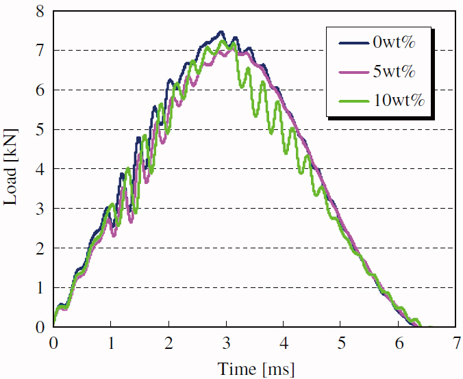
CFRPs were prepared using prepregs consisting of traditional carbon fibers and epoxy resin filled with CSCNTs(Yokozeki et al., 2007). The CFRP unidirectional laminates containing various contents of CSCNTs exhibited marginal improvements in impact damage resistance with reduced delamination area and increased compression after impact(CAI) strength as shown in Table 4. The results shown in Fig. 12 indicate that all specimens exhibited almost identical time histories, while the peak loads of the laminates containing CSCNTs were slightly lower than those of the neat
[Table 4.] Summary of impact properties (Yokozeki et al. 2007)
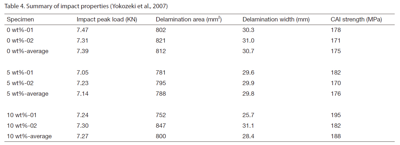
Summary of impact properties (Yokozeki et al. 2007)
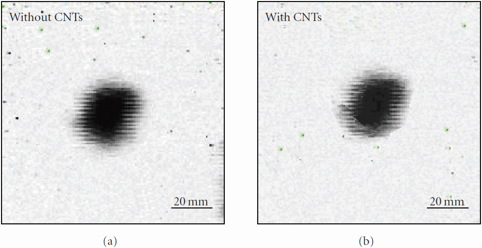
laminates. These results are inconsistent with the significant improvements in both mode-I and mode-II interlaminar fracture toughness with 5 wt% CSCNT loading (see Section 2.2). The disappointing impact results were attributed to the relatively thin specimen thickness of 3 mm, which deformed elastically rather than absorbing the impact energy through damage accumulation. Amino-functionalized DWCNT-CFRP composites were prepared by epoxy resin infusion and were subjected to low velocity impact (Inam et al., 2010). The results indicated only a marginal increase by up to 6% in absorbed energy and no significant effect on damage area (Fig. 13) as a result of adding 0.1 wt% DWCNTs. It was concluded that compared to standard rubber or thermoplastic toughened epoxy systems the enhancement in impact toughness of CFRPs containing CNTs was insignificant, and traditional methods, such as polymer blends or hybridization with other more ductile fibers, would have to be used for better results.
High CNT contents were shown to be more beneficial to impact damage and residual properties of CFRP composites(Kostopoulos et al., 2010). About 0.5 wt% MWCNTs were
dispersed in the epoxy matrix of CFRP quasi-isotropic laminates which were subjected to low velocity impact.Results showed that no significant difference was observed in delamination area or absorbed energy when low impact energies of 2-8 Joules were applied. However, the reinforcing effect of CNTs was more pronounced at high energy levels of 12-20 Joules where the CNT modified composites showed improved impact performance compared to the neat composites, in terms of a higher absorbed energy and a smaller damage area. At the high impact energies, the CNTs discouraged delamination crack propagation through crack arrest, resulting in a reduced delamination area, while the impact force remained at the same level.
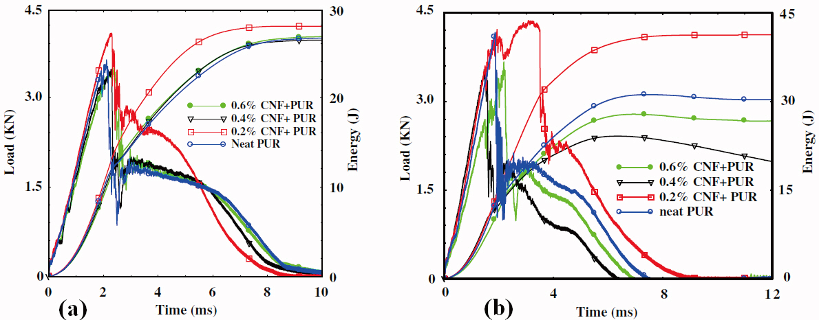
The addition of CNFs to core materials showed a significant improvement in impact performance of sandwich structures. Sandwich panels were fabricated using polyurethane (PUR) foam cores containing CNFs and CFRP composite face sheets, which were subjected to high energy impact (Bhuiyan et al., 2009). Sandwiches made from the CNF-PUR foam sustained higher peak loads and had smaller damage areas than the neat counterparts. Figure 14 presents the load and energy versus time plots for sandwich panels impacted at 29 and 44 J. The sandwiches containing 0.2 wt%CNF modified core structures showed the best performance in terms of peak load and damage area. The SEM images (Fig.15) indicate that the neat foam core exhibited collapsed cells,whereas the cells in the foams containing CNFs broke under impact due to the increase in cell wall thickness. Both the cell density and stiffness of the foam increased with increasing CNF contents. A similar conclusion was also drawn with the addition of nanoclay to the same structure in their earlier report (Hosur et al., 2008).
Damage tolerance refers to the ability of a material to survive a specific amount of damage (Hirai et al., 1998a, 1998b;Kim et al., 1993). The evaluation of the residual strength of a damaged structure is of practical importance for an effective damage tolerant design. Composite laminates with impact damage experience significant strength reductions when loaded under compression due to the local instabilities arising from the existing damage (Iqbal et al., 2009). Very few studies have hitherto been reported on the residual properties after impact of CNT-CFRP multiscale composites (Kostopoulos et al., 2010; Yokozeki et al., 2007). The CAI strength of CFRP composites showed an increase of about 8% due to 10 wt%CSCNTs, compare to neat CFRP composites, as shown in Table 4 (Yokozeki et al., 2007). This observation coincided with the results of non-hole compressive strength where an increase of 10% was observed for the composite with 10 wt%CNTs in the epoxy matrix, compared to neat composites.
While there was no detailed study of the mechanisms behind the CAI failure, a smaller delamination width of the laminate containing CNTs appears to be responsible for the higher CAI strength. The same conclusion was drawn previously (Kim et al., 1993) in that the failures in the CAI tests were dominated by the size of existing damage upon impact rather than subsequent propagation of the damage.The post-impact performance of MWCNT-CFRP composites was characterized by measuring the CAI properties and the compression-compression fatigue strength after impact(Kostopoulos et al., 2010). The inclusion of 0.5 wt% CNTs led to an increase of approximately 12-15% of both the CAI strength and modulus over the neat composites depending on the applied impact energy.
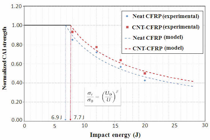
It is well known that there exists an impact energy threshold, below which a strength reduction may not occur.A simple model of residual strength has been widely used to correlate the CAI residual strength, σr, to the threshold impact energy, U0, based on the Eq. (1) (Hirai et al., 1998a):
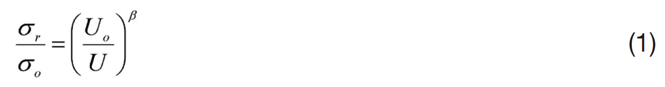
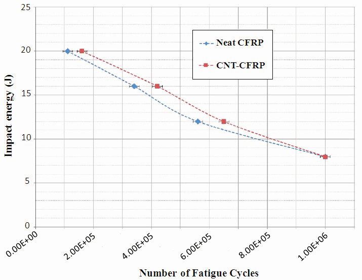
The threshold value, U0, and the damage exponents, β, can be determined from the least-squares fitted log-log plots of the residual strength data. Figure 16 presents the experimental data along with the analytical prediction of the impact energy threshold taken from the recent study (Kostopoulos et al., 2010). Threshold energy values, U0, of 6.9 J and 7.7 J(with β = 0.68 and 0.72) were reported for the CFRPs without and with 0.5 wt% CNT inclusion, respectively, confirming the beneficial effect of CNTs on impact damage tolerance of the CFRP laminates. In addition, the compression?compression fatigue tests of the composites were conducted after impact at a stress of 80% of the maximum CAI strength of each
impact energy level and a stress ratio of R = 10. The results indicated an extension of fatigue life for at least 20% for the CNT modified CFRP laminates compared to the neat CFRP laminates, as shown in Fig. 17. The bridging and pullout of unbroken CNTs that survived the impact loading contributed to the higher post-impact residual properties of the CNTCFRP composites.
It is worth noting that only a few aforementioned studies on impact performance of CNT-FRP multiscale composites are available in open literature. In addition, there has so far been no work reported on the impact damage resistance and tolerance of FRP composites with CNT-grafted fibers or fabrics, indicating the need for comprehensive experimental and simulation studies in this area.
This article aims to provide a comprehensive review of the strategies developed for the fabrication of FRP composites containing CNTs and CNFs, and the effects of the addition of these nanofillers on impact and delamination resistance of FRP composites. The research findings presented here demonstrate the potential for significant improvement of the impact and delamination performance of FRP composites at the expense of a modest weight gain, by dispersing CNTs in the matrix or attaching CNTs on the fiber/fabric surface.The useful properties of CNTs that contribute to this purpose include their very large aspect ratio, excellent strength and modulus, high strain to failure and unique reinforcing mechanisms on the nanoscale.
The techniques based on pre-dispersion of CNTs in a polymer matrix prior to impregnation of fiber reinforcements are simple and scalable for mass production. However, there are several critical issues that may limit the widespread use of these techniques: only a low CNT content, often lower than about 1 wt% of the resin, can be added because of the very high viscosity of the CNT-resin composite matrix arising from the high aspect ratio and the extremely large surface area of CNTs (Ma and Kim, 2011; Ma et al., 2010; Siddiqui et al., 2011). Inherently poor dispersibility of CNTs in many polymers and the needs for purification and functionalization of CNTs prior to mixing with resins, as well as lack of alignment and damage to CNTs during mixing, especially while ultrasonication, are other drawbacks of CNTs in using them as nanoscale reinforcement of the matrix material.The direct growth of CNTs on the surface of fibers/fabrics is one of the most promising strategies. This approach has the potential for providing a high concentration of well-spaced and radially oriented CNTs, eliminating the issues associated with poor dispersion of CNTs and the high viscosity of CNTresin mixtures. The grafting of CNTs on fibers improved the interfacial properties between the fibers and matrix,attributing to an increase in effective surface area, mechanical interlocking and local stiffening of the polymer matrix near the fiber/matrix interface (Qian et al., 2008; Sager et al., 2009;Thostenson et al., 2002). In addition, the presence of CNTs around the fibers or on the fabric surface in the matrix-rich region has shown to alleviate some of the vital drawbacks of conventional FRP composites, such as poor interlaminar fracture toughness as discussed in Sections 2 and 3.
It is clear from perusal of the literature that the addition of CNTs/CNFs renders FRP composites to resist crack initiation and propagation through improved mechanical properties of the matrix material, including the fracture toughness,strength and modulus. The mechanisms behind the improved delamination and impact damage resistance/tolerance of FRP composites due to the presence of CNTs generally arise from crack tip bridging and pullout of CNTs. Because of the microscopic length of CNTs, albeit their nanoscopic diameter,these two mechanisms can take place on a microscopic scale,which is considered an additional benefits of 1D nature of CNTs. The enhanced fiber/matrix interfacial adhesion due to the functionalized CNTs (Gojny et al., 2005a) and the fibers/fabrics with grafted or electrophoretically deposited CNTs(Bekyarova et al., 2007; Thostenson et al., 2002; Veedu et al.,2006) may also contribute to improved delamination and impact resistance through a large improvement in fracture toughness of the matrix material in various fracture modes.In addition, the CNT-modified multiscale FRP composites exhibited higher impact damage tolerance in terms of higher CAI strengths with less deflection than those without CNT reinforcements. Judging from the fact that the CAI residual strength of laminate composites is controlled mainly by the compressive strength of fibers and the stiffness of the matrix martial, in addition to the impact damage size and shape,the high damage tolerance of the FRP composites containing CNTs compared to neat composites is a manifestation of the less impact damage and the improved matrix stiffness arising from the presence of CNTs. However, these enhancements are obtained often at the expense of the ductility of the matrix, depending on the CNT concentration.
Substantial progress has been made in the development,processing optimization and microstructural control of CNT reinforced polymers with low CNT concentrations over more than a decade. However, exploitation of the exceptional properties of nanoscopic CNTs for macroscopic structures made from multiscale composites containing microscopic fiber reinforcements is still in its infant stage, and there lies many challenges ahead before their full application in advanced composites structures. This requires fundamental understanding of the properties and their interactions across the various length scales. Basic understanding of the synthesis?structure-property relations will enable the nanoscale material design for macroscale engineering applications. Extensive tests and characterization,accompanied by modeling and simulation, are further required to fully understand the mechanisms that govern the performance of FRP composites in the presence of CNTs/CNFs.
For large scale applications of CNTs, techniques need to be developed for mass production of defect- or impurityfree CNTs with improved properties and lower costs. The commercial availability of CNT-modified polymer products,such as CNT-modified epoxy resins, prepregs and sizing, is a step forward the development of large-scale CNT-based composites. Another interesting development in recent years is the production of CNT ropes with macroscopic length and micro- or macroscopic diameter through continuous synthesis followed by twisting of bundle CNTs (Zhang et al., 2002). Long CNT ropes would offer tremendous advantages over agglomerated short CNT bundles for applications in advanced composite structures. Similar to microscopic conventional fibers, they can be transformed into intermediate fiber form, such as continuous prepregs,2D/3D woven or knitted fabrics, that can ultimately replace or be combined together with conventional carbon fibers in the future.