Over the last decade, formation flight technology has become more important with the increasing number of commercial and military applications on multiple unmanned aerial vehicles (UAVs). Formation of multiple UAVs includes two major problems of: (i) how to guide each UAV to a formation position (Kim et al., 2002; Tahk et al., 2005), and (ii) how to maintain tight formation (Pachter et al., 2001; Ryoo et al., 2005; Verma et al., 2003).
If there are fixed obstacles such as mountains and enemy defense sites, path planning by trajectory optimization may be performed first. However, the possibility of collision with other members in the formation is high if there are large external disturbances or if the change of formation pattern is associated. Due to unexpectedness of collision with other mobile objects, it is difficult to construct a guidance law for formation flying of multiple UAVs. Ryoo, C. K. (2005) propsoed an optimal closed-form solution for formation guidance without collision avoidance is obtained first, and a command term for collision avoidance is added.
Because most autonomous formation flight methods require an active communication link between the vehicles, damage to the receiver or the transmitter and communication delay are critical to mission success. For the prediction of future state values, nonlinear model predictive control (NMPC) must know the acceleration of the other vehicles along all the future time horizons, and this problem is more critical. Passive detection of another vehicle would be much preferred to the methods for the formation guidance.
One possible method for passive sensing target information is to use visual sensors. Vision-based formation control has been actively studied in robotics (Das et al., 2002). The guidance laws for approaching and forming the formation using only line-of-sight (LOS) angles is proposed in Tahk et al. (2005). In Sattigeri et al. (2004), an adaptive approach to vision-based UAV formation control assumes that LOS range can be estimated by the visual sensors. Each vehicle in formation can measure its speed, heading, LOS range, and angle to other vehicles. The developed formation control assumes that the neighboring vehicles are stationary in formation and dynamic model inversion errors are adaptively approximated by a neural network. Another passive method for sensing the vehicles is to use the wake produced by the leading aircraft (Sutton and Bitmead, 2000). A neural network is used to estimate the relative position from the leader and the initial training phase of the neural network requires the follower to receive a relative position from the leader.
MPC refers to a class of control algorithms that use a process model to predict the output along a future time horizon of the system (Bhattacharya et al., 2001; Kouvaritakis et al., 2001) and calculates a control input sequence to optimize future system behavior using the receding horizontal concept at each step (Mayne et al., 2000; Michalska and Mayne 1993). Then, the MPC algorithm implements only the first control signal to the system and optimization is repeated at subsequent control intervals in real time. NMPC, the MPC for a nonlinear model and/or nonlinear constraints, can deal with explicit constraints on the inputs and the states. Therefore, the optimal formation guidance in consideration of collision avoidance can be constructed by using NMPC. One issue is that, in formation, each follower usually uses the relative distance, LOS angle, own motion information, and the acceleration intent along all time horizons for multiple vehicles in the formation flight. This requires communication between the vehicles. In this paper, the modification is made to use only the relative distance, LOS angle, and own motion information. The acceleration of the other vehicles is unnecessary in this modification, and the modified approach can solve sub-optimal formation problems in consideration of collision avoidance without data communication.
The leader-follower structure, which is a common formation structure, is considered in our paper. While the leader generates a formation trajectory for a common mission, each follower follows the trajectory generated by the leader and keeps its position within a specific distance in the leader-wingmen structure. Thus, in our paper, each wingman solves the optimal control problem including collision avoidance.
This paper is organized as follows. In the next section, NMPC for formation guidance is first introduced. After the formation guidance using NMPC is developed, the modification that uses only the estimation of other vehicle’s acceleration is introduced. The stability of the error dynamics between the modification and NMPC is also investigated. Simulation for three UAVs converging to a formation while avoiding danger of collision is presented to verify the performance of the proposed methods. Conclusions are provided in the final section.
2.1 Equations of motion for formation flight
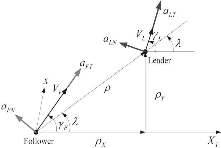
Consider the planar motion of two vehicles shown in Fig. 1. The two-dimensional point mass model is used in formation of a group of UAVs for simplicity.
In this figure, subscript F means the motion information of the follower and L denotes the information of the leader’s motion. ρ denotes the relative distance, λ and γ represent the LOS angle and the flight path angle, respectively. Furthermore, V represents the velocity of the vehicles. The I-frame is an inertial reference frame and all information of the motions of vehicles is described with respect to the inertia reference frame.
From the formation guidance geometry shown in Fig. 1, the relative distance of the follower with respect to the leader and LOS angle are given by

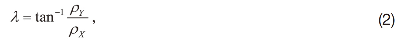
where ρX=ρcos λ, ρY=ρsin λ.
Then, the first and second time derivatives of the relative distance and the LOS angle are obtained as
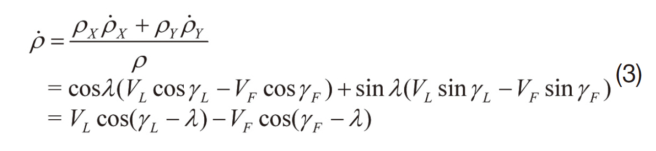
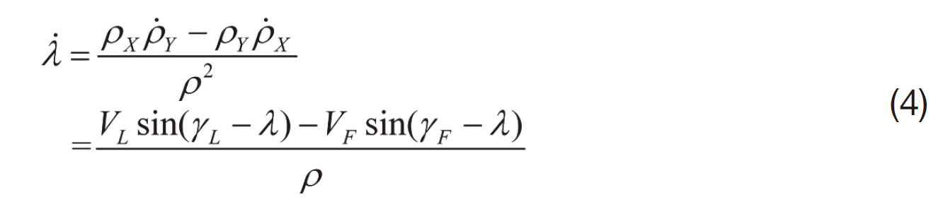
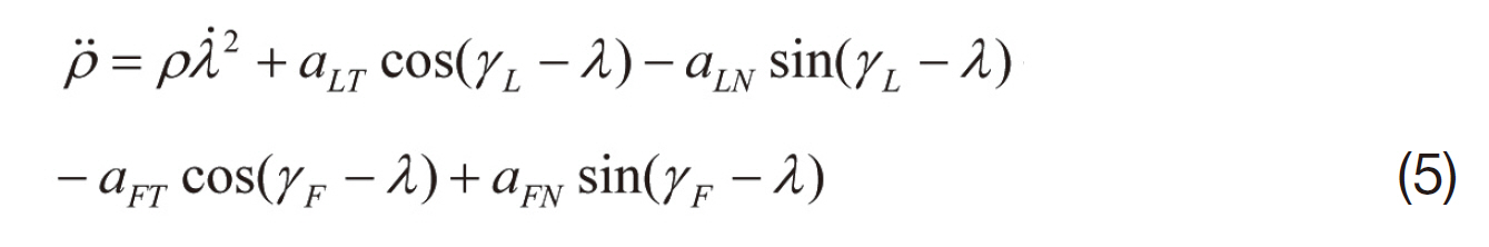
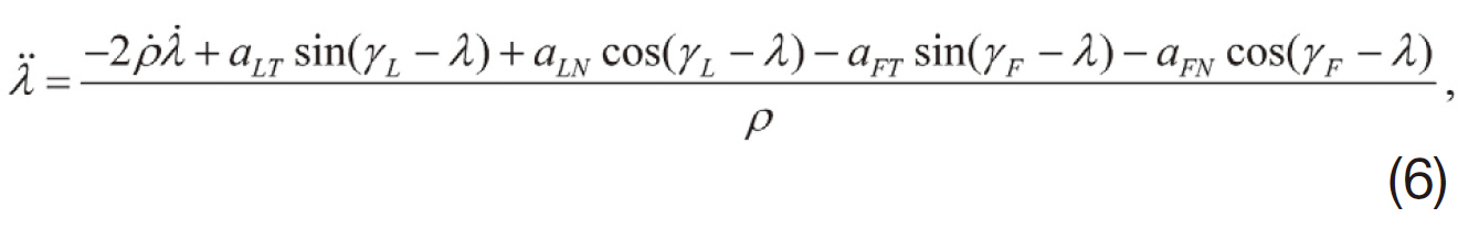
where αFT, αFN are the follower’s acceleration and αLT, αLN are the acceleration of the leader applied tangential and normal to the velocity of the each vehicle shown in Fig. 1, respectively.
Here γL can be obtained by applying simple algebra to Eqs. (3) and (4):
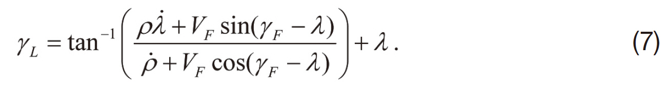
Therefore, the flight path angle of the leader can be calculated using the relative distance, LOS angle, and the velocity of the follower.
The equations of relative motion of the follower with respect to the leader can be described as
x˙=fc(x, u):
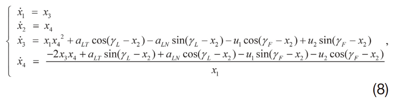
where


The discrete-time versions of Eq. (8) are considered in implementing NMPC,

where x(i)∈R4 denotes the state vector at time step i, u (i)∈R2 denotes the control input vector.
Discrete-time equations of motion are represented as follows;

where ΔT represents sampling time.
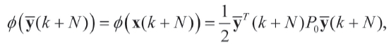
To guide and keep the formation, the proper desired output should be determined. Let us define the output and desired output, respectively, as follows

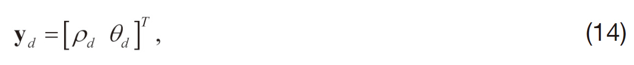
where θ=γL?λ. This desired output can be determined according to the formation shape, and vehicles can make and maintain formation when the output of the follower tracks the desired output.
An NMPC algorithm calculates a control sequence to optimize the future system behavior at each event (x, k) (i.e. for initial state x at time k). The initial values of the state vector of each event are defined as

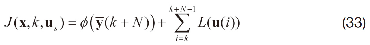
The optimal control problem considered in this paper is as follows.
NMPCF:
subject to Eq. (10), with the input constraints of

where us={u(k), u(k+1), …, u(k+N?1)}, y?=yd?y, umax=2g, g is gravity (9.81 m/sec), and Sj(x(i)) denotes state inequality constraints.
In this paper, collision avoidance is considered as the state constraints. We set the state constraints as follows

where Rc denotes the radius of collision, and ρj(i) represents the relative distance between our own vehicle and the j-th wingman at time step i. When the distance between the UAVs is less than or equal to Rc, the danger of collision exists.
2.3 Open-loop optimization for NMPCF
It is difficult or impossible to find the analytic solution of an NMPC problem. Therefore, numerical optimization is necessary and we have considered the approach of Sutton and Bitmead (2000) to solve the NMPC problem.
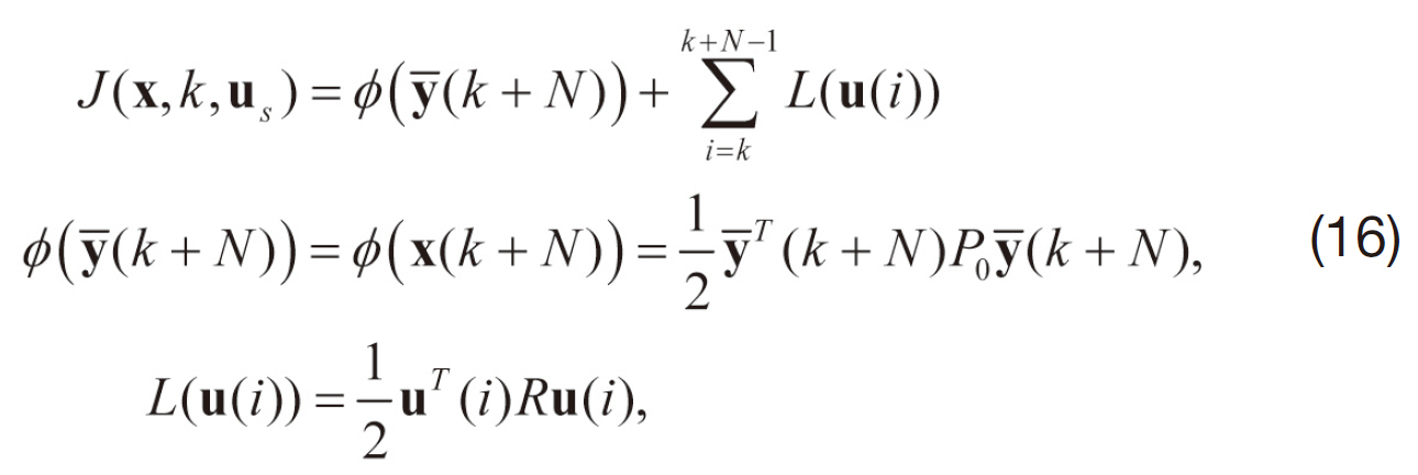
As shown in Bryson and Ho (1975), an augmented cost function of Eq. (16) can be derived using the vector Lagrange Multiplier sequence {λk∈R4 : k=1, …, N} and integral penalty functions:
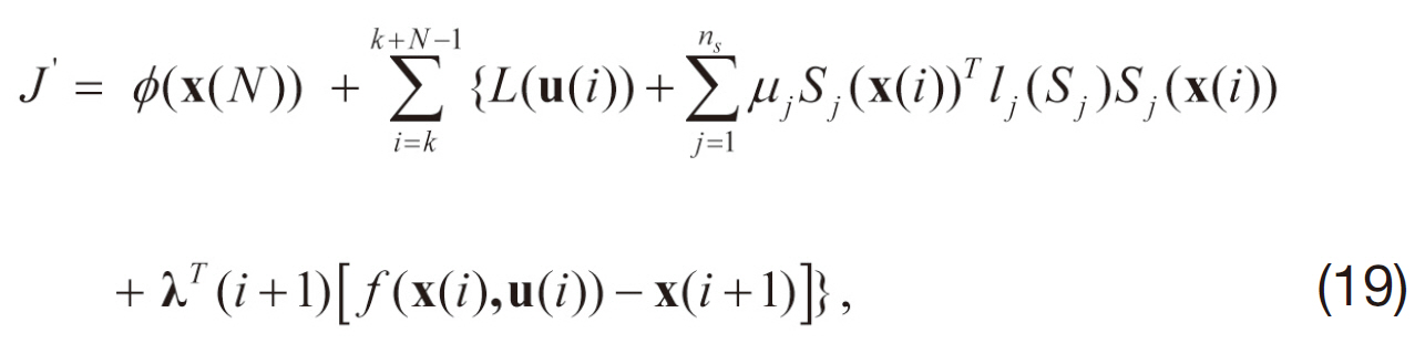
where ns denotes the number of state constraints, μj is a constant weighting factor of the j-th state constraint, and
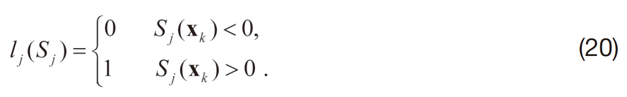
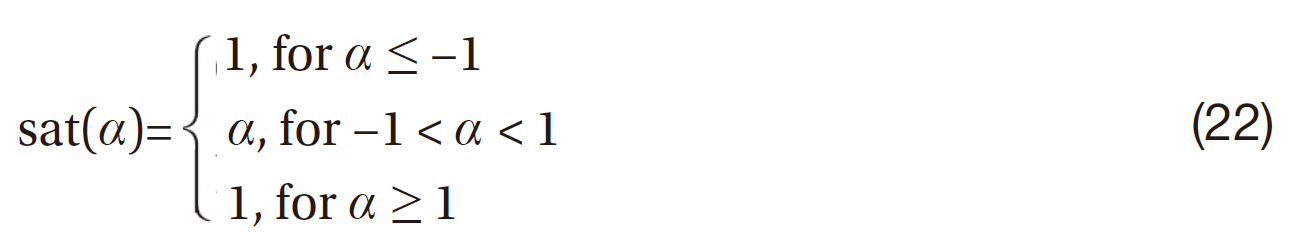
In this paper, input constraints (input saturation) are addressed by bounding the input with the maximum control value when computing the new control input sequence during the optimization process by setting

where
The Hamiltonian function is defined as

Then the variations of the augmented cost function is obtained as
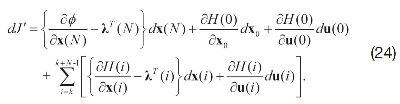
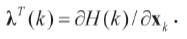
By defining the Lagrange multiplier as

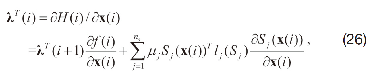
we can simplify the variations of the augmented cost function dJ’ as
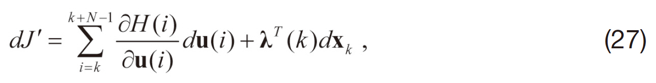
and we have
where
At each time step, the online optimization process at a given initial state is Kim et al. (2002):
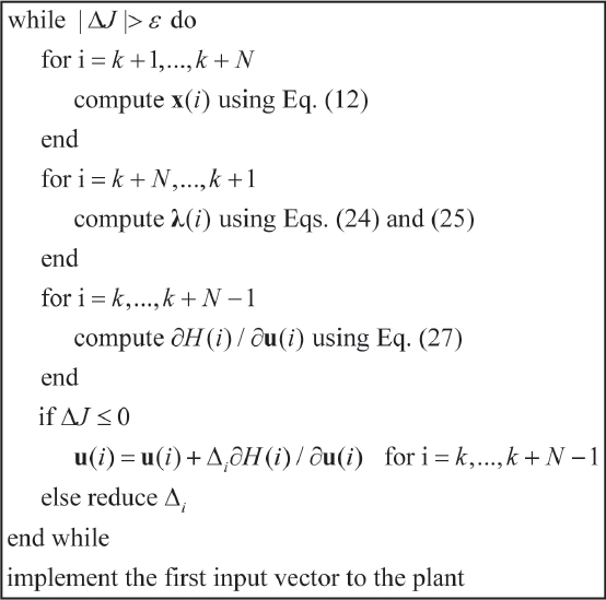
To reduce computation time, the initial control input sequence at each time step is taken as {uk+1, …, uk+N?1' uk+N?1}which is obtained in the previous time step.
3. Modification of NMPC Formation Guidance Law
As shown in Eqs. (8) and (10), we must know the normal and tangential acceleration intent of the leader along the future time horizon to predict the relative motion of the follower. If the follower does not know the acceleration intent of the leader and other followers, i.e., data communication between the vehicles is impossible, the performance of the proposed NMPC degrades significantly. In this section, we propose a modification to the proposed NMPC framework to overcome this problem. The proposed modification uses only the LOS angle, the relative distance, and the motion of the follower. Therefore, data communication between UAVs is unnecessary to guide and maintain formation with the proposed modification.
Now, let us describe the modification of the formation guidance using the NMPC procedure using the above approach.
Define a as
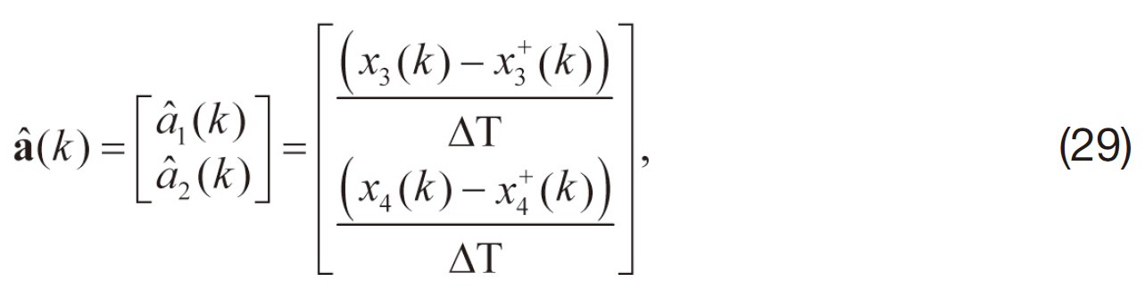
where χ3(k), χ4(k) are the initial relative distance and LOS angle rate of the follower at time k, respectively. χ+3(k), χ+4(k) denote the k-th optimal relative distance and LOS angle rate resulting at (k?1)-th optimization step, where k=0 at the first optimization step. It is assumed that a(0)=[0 0]T for simplicity.
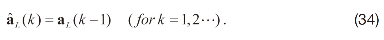
We define aL(k) as follows:
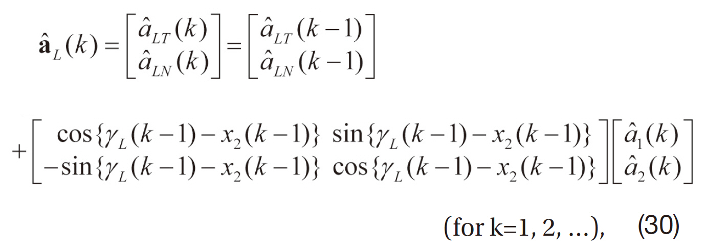
Next, we modify the discrete dynamic equation by substituting aL(k) for the leader’s acceleration intent at the k-th optimization step,
Then, the NMPCF problem is modified as follows:
NMPCF-M:
subject to the modified discrete dynamic equation, with the same input and state constraints as NMPCF ones.
Note that any information of the leader’s motion is not used in the proposed modification. Therefore, the communication between the vehicles is unnecessary in the modification for formation guidance.
3.2 Stability of the modified NMPC law
In this section, we mention the stability of the error dynamics between the NMPC for formation and the modification. To refer to this stability, it is assumed that the acceleration of the leader is bounded and converges to a constant. As usual, the acceleration of the leader and other vehicles are assumed to be bounded in magnitude. Therefore, the assumptions are reasonable.
From Eqs. (8), (29), and (30), we have
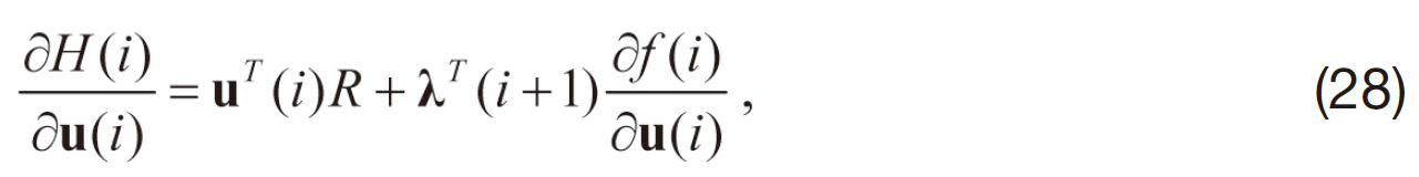
For a stationary solution dJ’=0 for arbitrary integer k; this can happen only if

Then, the optimal command can be obtained
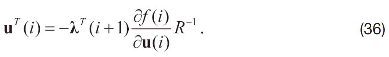
Note that the matrix R should be nonsingular for the existence of solution.
From Eqs. (8), (12), (25), and (26), it is clear that the performance of the formation guidance depends on the accuracy of the estimation and prediction of the leader’s acceleration. Therefore, the solution of the modified NMPC will differ from that of full-information NMPC. However, the difference will be continuously reduced if the acceleration of the leader is bounded and converges to a constant.
The desired output for the optimal formation guidance represents the desired position of the follower about the leader shown in Eq. (14). The cost function of the two proposed NMPC for formation is defined to guide and maintain the formation and to minimize the guidance command. At every k-th optimization step, the difference of the desired positions of the two NMPC for formation is bounded and reduced to zero due to the assumption that the acceleration of the vehicles is bounded and converges to a constant.
The boundedness of the error dynamic system is deduced from the above facts. Therefore, the error dynamic system between the modified NMPC and the full-information NMPC for formation is stable. Moreover the modified formation guidance system is stable when the proposed formation guidance system using NMPC is stable.
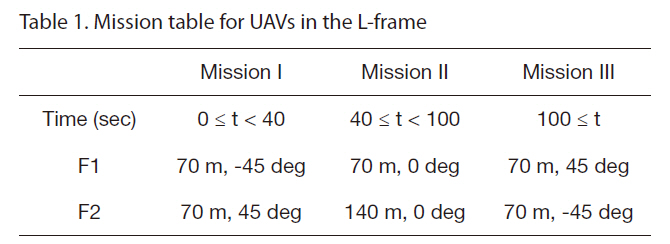
In this section, the modifications for formation are applied to three missions described in Table 1 for verification. The desired output is represented in this table, time is zero when the optimization procedure is started and F1, F2 denote the follower 1 and the follower 2, respectively. If UAVs achieve three missions, UAVs change the formation pattern. The performance of the proposed modification is analyzed from three points of view: (i) performance depredation from the lack of the acceleration information of others; (ii) performance analysis of the proposed modification and NMPC for formation; (iii) boundedness of the error dynamics output mentioned in Section 3.2.
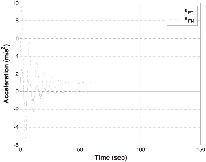
Leader’s acceleration vector is as follows:
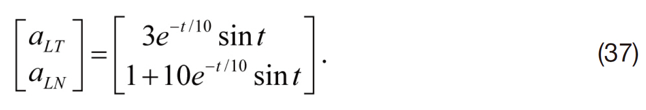
This leader’s acceleration pattern is depicted in Fig. 2. The acceleration of the leader is oscillated, but the amplitude of
[Table 1.] Mission table for UAVs in the L-frame

Mission table for UAVs in the L-frame
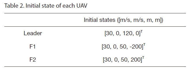
[Table 2.] Initial state of each UAV

Initial state of each UAV
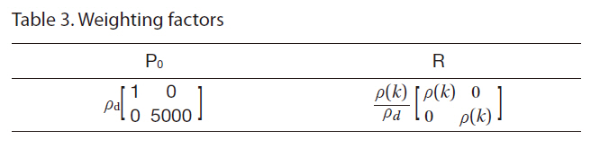
Weighting factors
oscillation decreases until the leader’s acceleration converges to a constant. This satisfies the assumption that the leader’s acceleration is bounded and converges to a constant. The initial states of the UAVs, which are described by the velocity vectors and positions of each UAV in the inertial reference frame, are given in Table 2.
The NMPC algorithm could fail to achieve formation due to a finite horizon and limitations of the input/state. In that case, the command input is likely to be saturated because it try to make formation as much as possible at a given future horizon. To avoid this problem, the variable weighting factor is taken in numerical example as in Table 3. In Table 3, ρ(k) is the initial relative distance at the k-th optimization step.
The modification of NMPC for formation does not use the leader’s acceleration. Therefore, the only performance degradation of NMPC for formation from the lack of leader’s acceleration is addressed in this section.
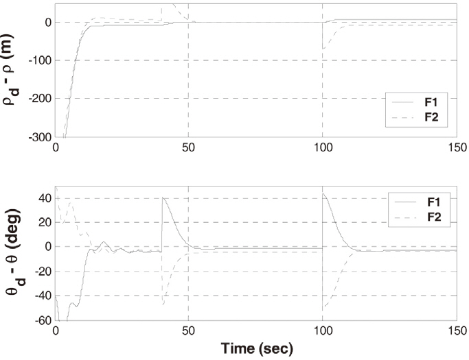
If there is the communication or measurement failure, it is assumed that the acceleration of the leader is zero. Figure 3 shows the history of the error between the desired output
for formation and the output of NMPC for formation. All the followers display the output error in NMPC for formation, because they do not know the acceleration vector of the leader. NMPC compensates for the missed distance to a certain extent.
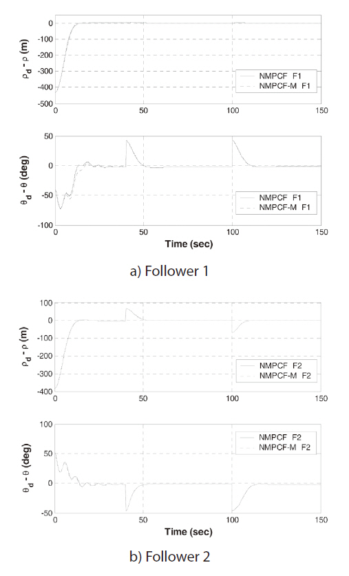
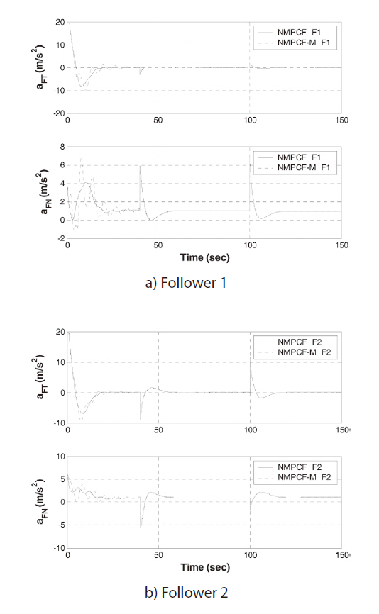
In this paper, the radius of collision is 30 m. The UAVs can form the formation and avoid collision when the terminal relative distance errors are close to zero and the minimum distance from each other satisfies the state constraints for collision avoidance. The results of optimization are represented in Table 4 and Figs. 4 and 5. As shown in the optimal results, two methods can make formation and avoid collision for every mission and the performance of the modification is similar to that of the formation guidance using NMPC with full information. The optimal commands of NMPC for formation and the modification are different at the beginning but this difference diminishes by 40 seconds.
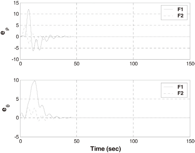
4.3 Boundedness of the error dynamics output
To check the stability of the error dynamics represented in Section 3.2, we compare the outputs of the modification
[Table 4.] Terminal relative distances and the minimum distance between UAVs
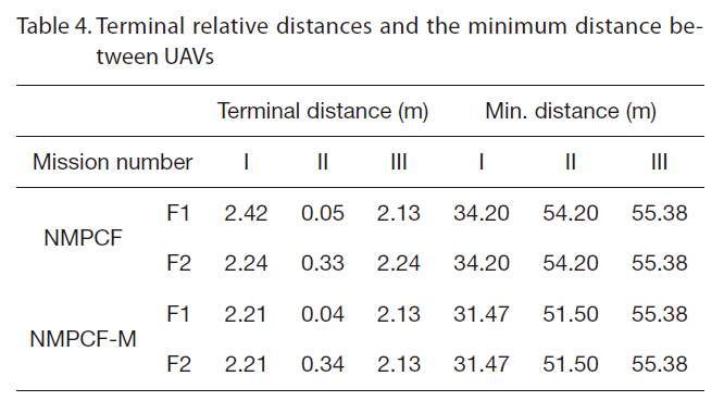
Terminal relative distances and the minimum distance between UAVs
and the formation guidance using NMPC. As shown in Fig.6, the output error between the two approaches oscillates at the beginning but this error remains bounded. Moreover, this error decreases and goes to zero.
In this paper, an online optimal control method for formation of multiple UAVs has been proposed. The main idea of this paper is to solve the optimal formation guidance problem with collision avoidance using LOS information, the relative distance, and own motion information for the online optimization. Under the assumption that each vehicle exchanges all estimated states and acceleration with each other every moment, the formation guidance using NMPC is proposed firstly. If this assumption holds, the solution of NMPCF can be applied to formation guidance with a collision avoidance problem in real time. However, there are many operations in which this assumption is inappropriate due to communication failure or delay. The modification of NMPC for formation guidance has been constructed and the stability of error dynamics between outputs of the formation and the modification is derived. Each follower uses the relative distance, LOS angle, and own motion information to solve the optimal formation problem in this modification. The modification is successfully tested on a three-vehicle formation and changing formation pattern. The performance of the modification has been validated by comparing the optimization results of the full-information NMPC for formation and those of the modified NMPC. The method suggested in this paper can be easily applied to various problems related to formation flight of multiple UAVs. Especially, the proposed approach will be helpful when a minimum communication profile is required between the formation vehicles and there is the danger of collision.