Quadrotor development has gained popularity among academic researchers. Developments in research led to the proposals of several techniques and methods of modeling for the simulation and control design of quadrotor (Altug et al., 2002; Bouabdallah et al., 2004; Hoffmann et al., 2007a; Jenie and Budiyono, 2006; Mian and Wang, 2008). Quadrotor structure and dynamics are simpler than conventional helicopter rotors or coaxial-rotors, allowing quadrotor to have less control complexity (Canetta et al., 2007; Coelho et al., 2007). However, the quadrotor is an unstable system. Consequently, the first design issue that must be addressed for an autonomous system is developing and implementing an attitude stabilization control.
Progress has been achieved during the preparation stage in regards to quadrotor development over the course of one year. Since the quadrotor contains four powerful rotors running at very high revolutions, many obstacles have been met and must be overcome. A most pressing obstacle is developing an attitude sensing quality. The vehicle experiences a high magnetic field produced by the brushless motors. Additionally, the vehicle experiences a very high vibration from the propulsion system. Only an adequate sensor can measure correct values in both circumstances. Consequently, we must develop a light-weight device that is to be attached on the frame. The challenge finding a low-cost inertial sensor performs well.
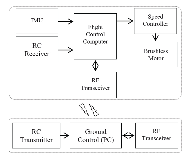
The propulsion system comprises 20cm diameter double blade propellers and brushless motors assembled on a very stiff design of the mainly carbon-fiber airframe. The flight control system is driven by an NXP LPC1768, an ARM-7 microcontroller that operates in 100 MHz of system clock, and consists of data acquisition system for acquiring six degree of freedom inertial sensor data from XA3300 at maximum 100 Hz of frequency and a flight controller that processes the control algorithm. The microcontroller directly drives the four channels for four electronic speed controllers through an i2c protocol; thus, we feel confident in achieving a fast response propulsion system rather than using a pulse-width modulation speed controller.
Figure 1 illustrates the quadrotor system’s ability to be controlled autonomously by the ground control system through the 900 MHz of radio modem; otherwise, the pilot can take over manually using radio control. The flight control system also has ability to auto lock the command input in the standby mode as a safety system, and then receives some special command input as a password to unlock.
A 1,200 mAh 11.1V Li-Po battery was used to drive all the electronics and the four 2,500 rpm/V brushless motors. The battery health system in the flight controller prevents an uncontrolled situation such as the power going down or controls the exhausts during the flight, making the quad-rotor land automatically.
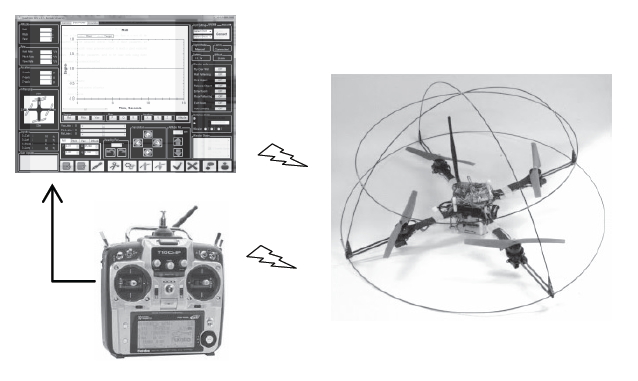
Figure 2 shows the three elements required during the flight test; the quadrotor itself, the radio controller for manual piloting and ground control software on a personal computer for monitoring and autopilot. In Table 1 we provide the detail of weight of the quadrotor.
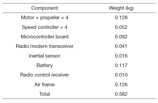
Detail of weight
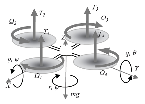
We introduce our quadrotor model based on the dynamics involved in the quadrotor as shown in Fig. 3. The main motion factor is the four cross configuration rotor’s speed; the motion can be varied by changing this speed (Bresciani, 2010; Leishman, 2002).
The thrust (T1, T2, T3, T4) of each rotor are generated from rotation speed of the motors (Ω1, Ω2, Ω3, Ω4) and the aerodynamics of the propeller blade. The thrust generation represented as following equation:
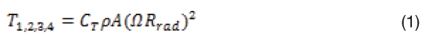
where
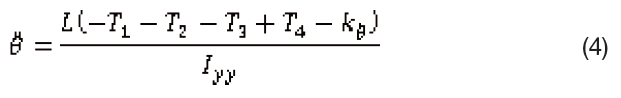
Two rotors (Ω1 and Ω3) are rotated clockwise while the remaining two (Ω2 and Ω4) rotate counter-clockwise. Based on this configuration, the yawing motion (
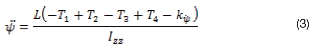
Generating a variation in the thrust
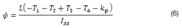
The rolling motion (p, φ) can be created by generating a variation in thrust
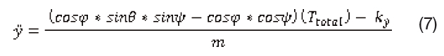
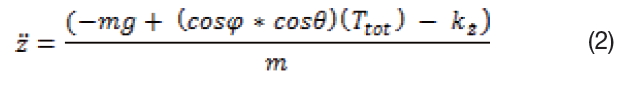
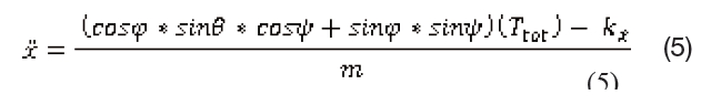
where m is the total mass,
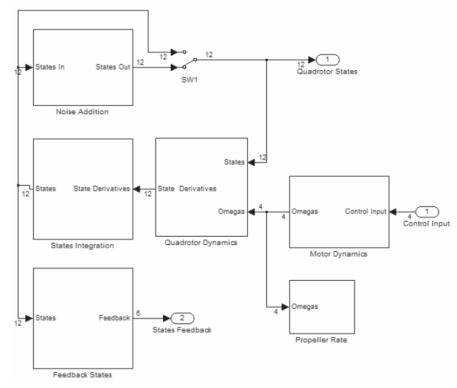
We built the model on MATLAB/Simulink software for simulation and as basic reference for designing the control system. As shown in Fig. 4, the model was divided into several blocks. Each block required its own validation process according to the real system. In general it takes into consideration the rotor dynamics and quadrotor dynamics. we used to rotor transfer function from a previous modeling project(Putro, 2010) with an additional response time delay due to the communication exchange between microcontroller and speed controller.
4. Control System and Experiment
For validation purposes, we implemented a proportional-derivative controller on the quadrotor in order to acquire flight data to compare to the simulation. (Gurdan et al., 2007; Hoffmann et al., 2007b)
4.1 Proportional-derivative control
A control input using a standard helicopter joystick raido control was employed in which at least four control parameters exist: the vertical control (δ

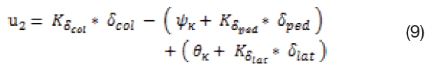
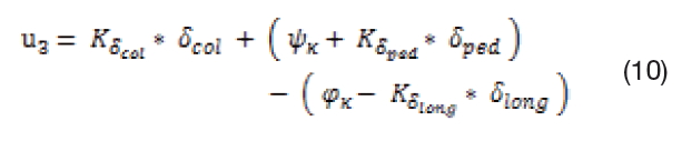
where ψk; ψk; θk are the outputs of attitude control loop.
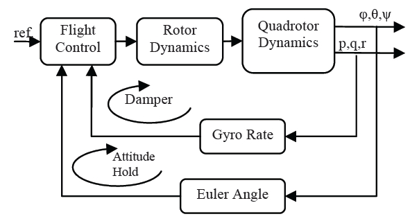
The first control algorithm that we implemented is shown in the Fig. 5. The system consists of a damper and an attitude holding for the roll, pitch and yaw. The control linkage is represented by the rotor dynamics of the devices that link the control output to the dynamics of the vehicle in certain constants (Jenie and Budiyono, 2006). The base controller uses a reference of zero, also known as the equilibrium, due to the hovering mode of the quadrotor. Experiments were conducted to determine the control parameters one by one for the all members of the SISO from the inner loop to the outer.
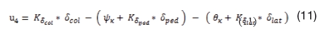
Firstly we implemented the proportional control described by Eq. (11) for the damper, utilizing the rate gyro sensor data to stabilize the angular rate in each axis.
The proportional control was implemented for each angular rate (p, q, r), examining the maneuverability of the vehicle. The low damping ratio maintains the vehicle in a frisky unstable system otherwise the vehicle will be sluggish.
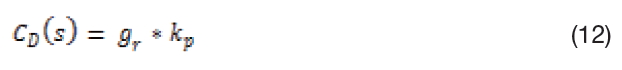
In the next step, we implemented the PD controller for attitude holding described by Eq. (12), for the roll, pitch and yaw.
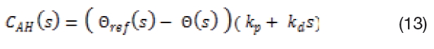
Simply taking the sum of Eqs. (12) and (13) produces the total inner-loop control Eq. (14).

Where:
CD(s) : rate damping controller
gT : rate gyro
kp : proportional gain for rate damping
CAH(S) : attitude holding controller
θtcf(s) : input reference
θ(s) : current position
kD+kds: PD gain for attitude holding
C(s) : total control output
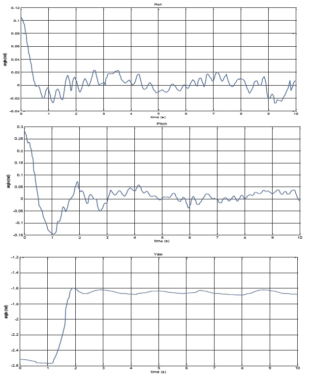
Satisfying the all gain condition (roll/pitch: P = 1.05, D = 0.275 and yaw: P = 1.15, D = 0.35) through experimental direct tuning on the test bed results in ‘able to fly’ performance as shown in the Fig. 6.
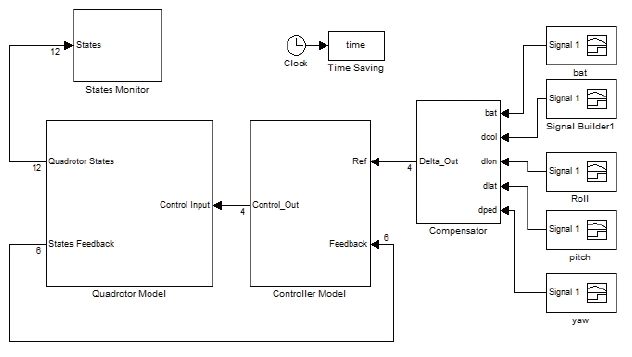
We used the flight data based on this result to validate the model. In Fig. 7, our model includes the feedback control as a stability augmentation system containing the same gain adapted in the radian unit.
The pilot should correct the throttle input due to the voltage drop in order to maintain the vehicle in a hovering flight state during the flight test. When the battery goes down after several time of flight, the throttle input should be increase to generate a constant thrust. We implement a compensator block in the simulation to compensate a variable value from the joystick of the radio control that was recorded in the flight data. The compensator adjusts the throttle coefficient factor due to the battery voltage drop during flight.
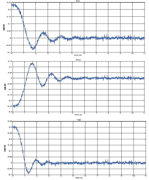
With noise added to the signal feedback the model runs the PD control on simulation. Figure 8 shows the results of the control response necessary for achieving the hover flight mode in which the oscillation frequencies are slower than the oscillation frequencies of a real vehicle.
4.2 Validation of quadrotor model
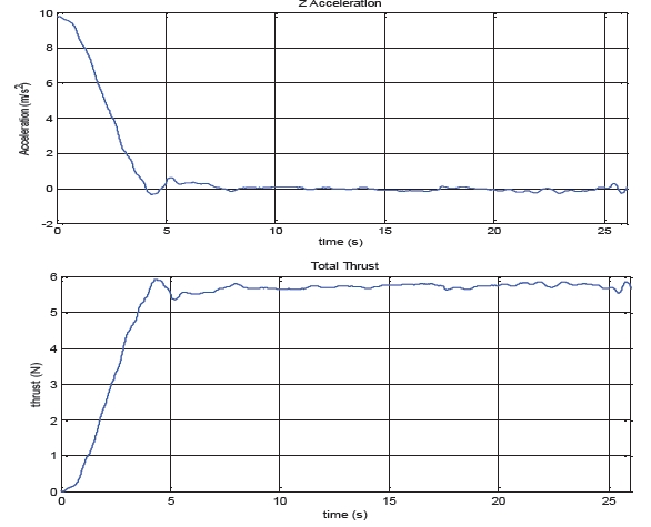
In order to achieve the hover flight mode, we assumed that the acceleration in the vertical axis was null, drag was equal to zero and the vehicle weight was 0.582 kg.
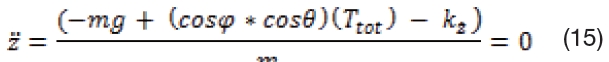
Obtaining the total thrust required for a hovering flight is described by:

The validation result shown in Fig. 9 under the simulation.
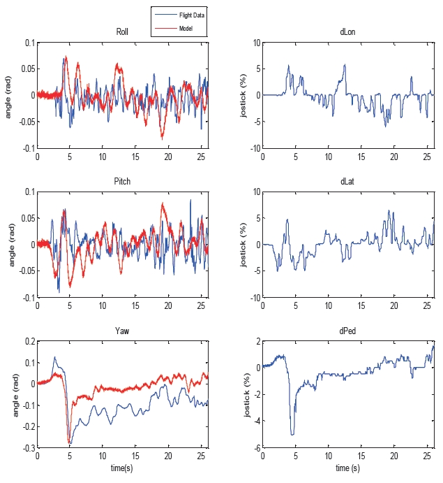
Finally, we generated flight data from the simulation in order to build a comparison to the real flight data. The model generated results that were similar to the real flight data.
As shown in Fig. 10, a comparison result of real flight data and simulation according to the same input excitation from radio control. The attitude was stabilized, and we confidently plan to design and implement an optimal control based on this result.
4.3 Linearized quadrotor model
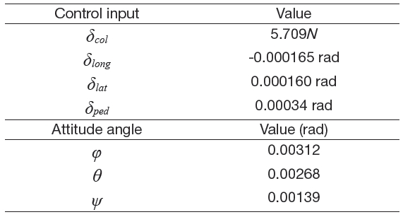
The validated model was a non-linear model; thus, the model needed to be linearized around its operating point. We decided to linearize the validated model through the Simulink/MATLAB utilities of the control design and analysis with some defined trim conditions. We considered the trim conditions from the stable condition of the quadrotor during the hover mode. The trim condition of each control inputs and attitude angles are shown in Table 2.
[Table 2.] Trim condition during hover

Trim condition during hover
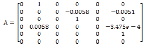
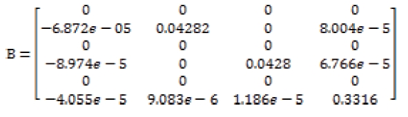
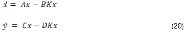
We presented the linear model form in a state-space form, x˙=

Input:

The A and B matrices with the exception of very small values are represented as follows:
We considered performing a controllability check for our state-space model, and then it was satisfactory to implement the linear-quadratic controller in the simulation. This control law is composed of a cost function:

This, in turn, will be minimized by the feedback defined as:

where C is a 6x6 identity matrix and D is zero. By substituting Eqs. (16) into (15), the system and the controller are now represented as follows:
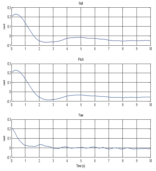
By changing Q and R we obtained the result shown in Fig. 11 with the gain matrix as:
[Fig. 11.] Control responses to stabilize the attitude by linear-quadratic controller in simulation.

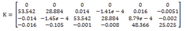
This gain control results a control response as we had expected; the feedback attempts to stabilize the angle in the equilibrium point. Figure 11 shows the simulation results. The roll and pitch response was slower than that of the yaw; thus, we conclude that the roll and pitch attitude was sluggish and also slightly deviated from the zero point, which is known as steady-state error.
In order to validate the results acquired from the simulation, we intend to implement the linear-quadratic in a real time system for future studies. Our future work will entail improving the K matrix, since the value obtained from K matrix appears to be too high in comparison to the control gain in the real system.
The quadrotor has already been built has exhibited the ability to fly with an inner-loop control. The model has already been established, with the inclusion of the same feedback control as that of an actual system, such as the stability augmentation system. Validation in the hover mode was satisfactorily satisfied for designing an optimal control based on modeling, such as an linear-quadratic controller that has already been implemented during simulation. Since the simulated system showed slight differences in comparison to an actual system, future improvements are necessary. The gain parameter obtained from the simulation can be easily added to the embedded controller in order to improve the performance of the quadrotor attitude control.
Continuing research for this project is necessary in order to establish an autonomous control system using modern approaches for real vehicles. We plan to implement the linear-quadratic controller as well as other modern control techniques in future work. Showing comparative results of real flight test data using several modern control methods are part of our plans for improvement. An altitude holding system will be added to perform a fully autonomous hover control system. The quadrotor will then be ready to use in flying robot applications.