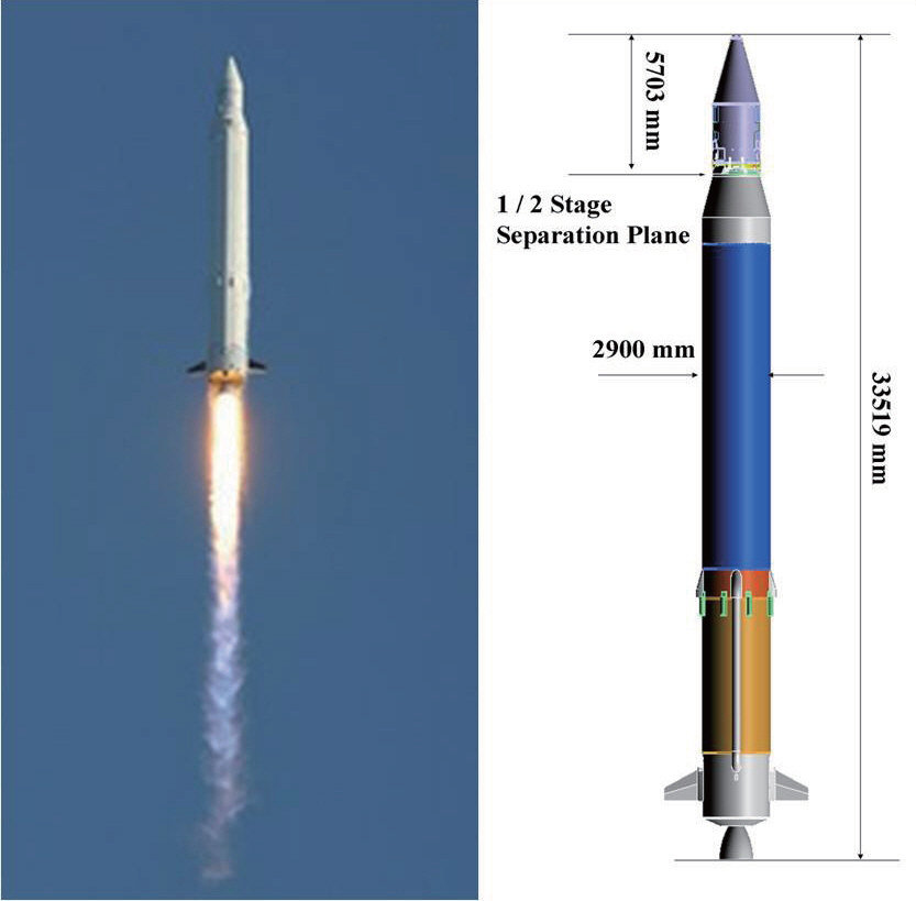
On August 25, 2009, the first Korea Space Launch Vehicle,KSLV-I, was launched, as shown in Fig. 1 The KSLV-I is a two-stage launch vehicle. The payload is STSAT-2, a scientific satellite of 100 kg. The target orbit is a low Earth orbit with perigee altitude of 300 km, apogee altitude 1,500 km, and an inclination of 80 degree. To guide the KSLV-I through a nominal trajectory up to the target orbit, several attitude control systems are used. Typical control systems are thrust vector control (TVC) systems and reaction control system(RCS), which are commonly used for many launch vehicles worldwide.
The first stage of KSLV-I has one liquid engine which can be swiveled by TVC actuators. The TVC actuators control the pitch and yaw attitude of the KSLV-I during the first stage flight. For roll attitude control, additional control systems are applied. First stage attitude control systems operate from lift-off until stage separation. The second stage has two TVC actuators, which swivel the nozzle of the second stage kick motor, and an RCS using cold nitrogen gas. The second stage attitude control systems stabilize attitude errors from stage separation until payload separation in order to target the flight direction exactly to the satellite mission orbit.
Generally, an onboard autopilot consists of several attitude controllers. Attitude controllers need to be properly designed in order to handle onboard attitude control systems.The controllers must guarantee sufficient stability margins regardless of system variations and environment changes.
In this paper, an attitude controller design and a test of the KSLV-I upper stage are introduced. First, the overall configuration of the upper stage control system is presented.Controller design problems and the corresponding results will be explained. The stability and performance of the designed controllers is verified via hardware in the loop(HIL) tests. Lastly, the flight test results relating to the upper stage attitude control is discussed.
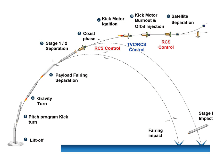
The nominal flight sequence of KSLV-I is shown in Fig. 2.The payload fairing is separated during the first stage flight.After the upper stage is separated from the first stage, the upper stage attitude control systems start to operate. During the coasting phase before kick motor ignition, the threeaxis attitude errors are controlled by RCS. When the upper stage kick motor generates thrusting forces by burning the solid propellant, the pitch and yaw attitude is controlled by TVC actuators and the roll attitude is controlled by RCS.After the kick motor burns out, three axis attitudes are again controlled by RCS as in the previous coasting phase. The upper stage enters the target orbit at the end of kick motor combustion. The satellite is inserted into the target orbit after it is separated from the upper stage during coasting phase.
2.2 Configuration of KSLV-I upper stage
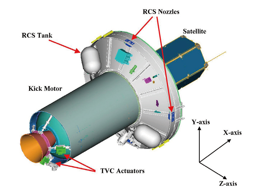
As mentioned above, the attitude control system of the KSLV-I upper stage consists of two electro-hydraulic actuators and an RCS using cold nitrogen gas. The electrohydraulic actuators change the direction of thrusting force to produce lateral torques, which controls the pitch and yaw attitude errors during the upper stage accelerating phase.The maximum deflection angle of TVC nozzle is limited to 3 degrees for each axis. The nitrogen-gas RCS, which has twelve nozzles of 22 Newton force per each, controls threeaxis attitude errors during coasting phases of upper stage.Figure 3 shows the configuration of KSLV-I upper stage.
RCS nozzles are located on the outer wall of upper stage.
Among twelve RCS nozzles, two nozzles are used for pitch attitude control, another two nozzles are used for yaw attitude control, and the other eight nozzles are used for roll attitude control. The coordinate system of the upper stage is also shown in the figure. The pitch and yaw attitude is defined with respect to the Z and Y axes, respectively. The origin of the upper stage coordinate system exists on the stage separation plane.
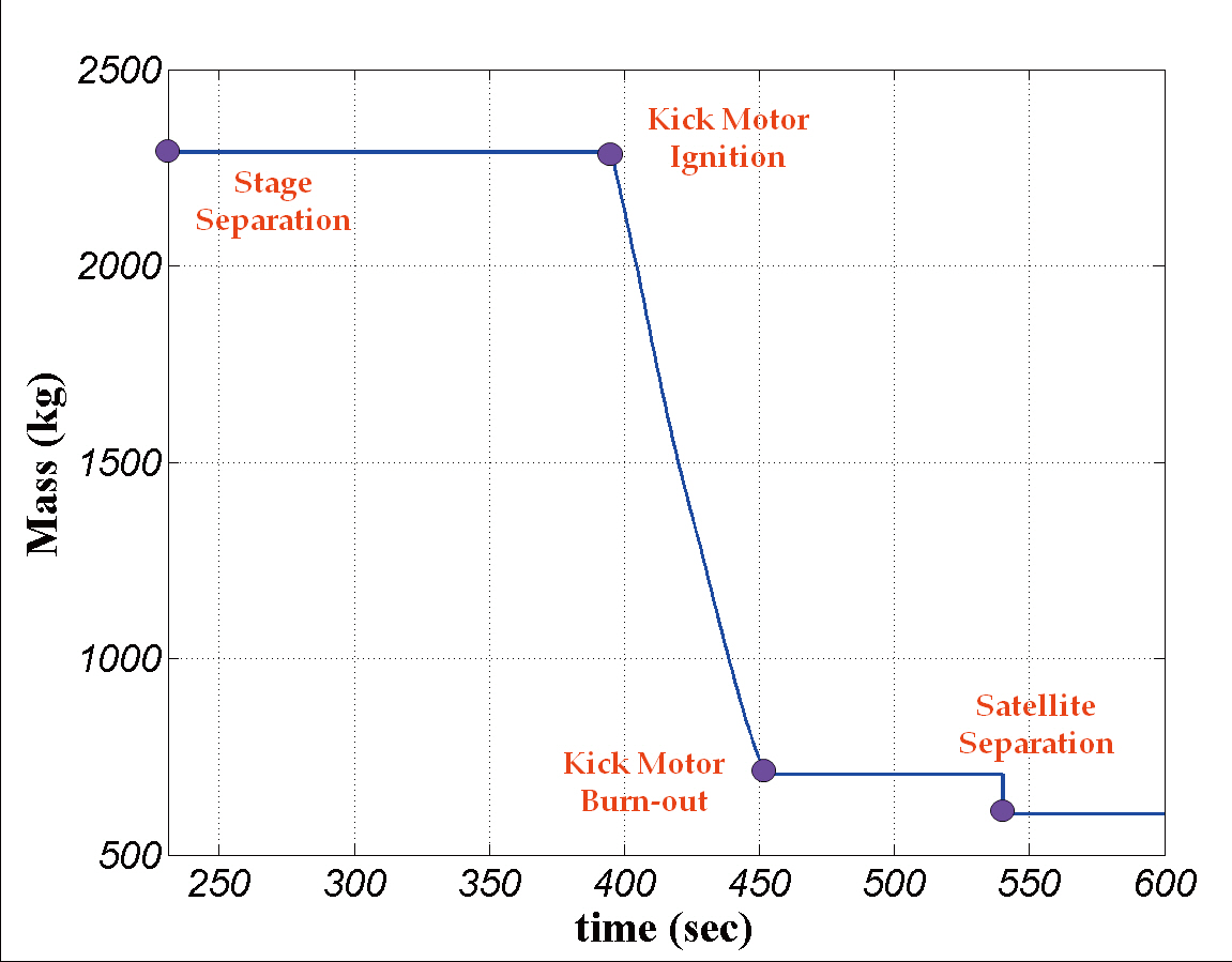
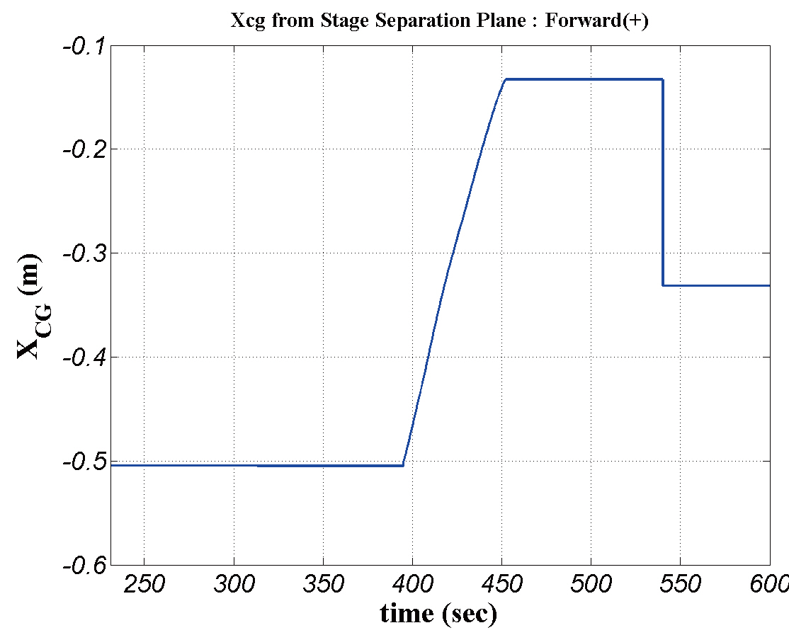
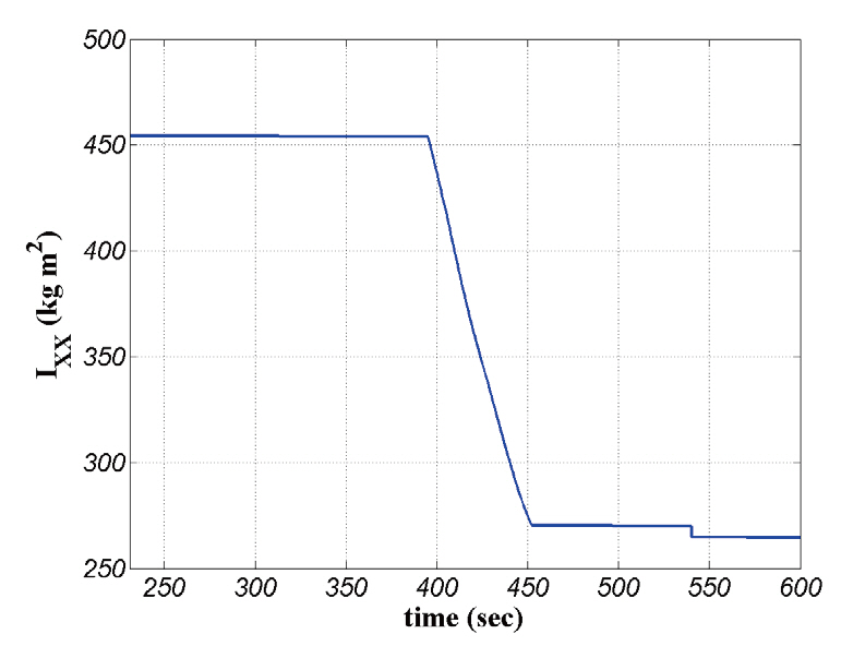
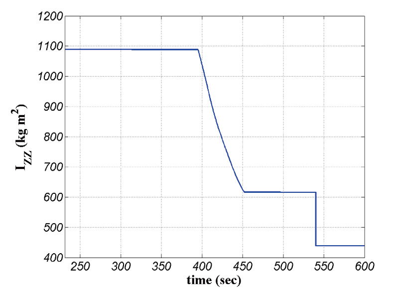
Mass data of the KSLV-I upper stage are displayed in Figs.4-7. System variation during the coasting phase is sufficiently small, but system variation during the thrusting phase is severe according to solid propellant burning out.
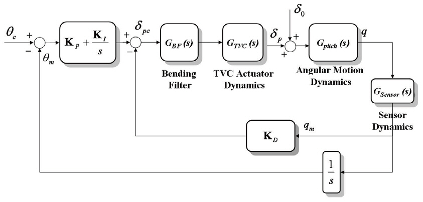
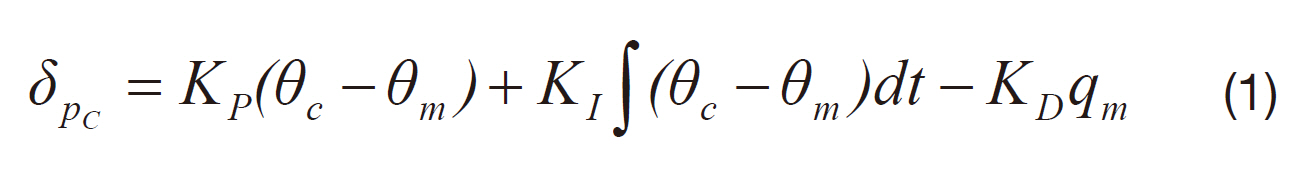
A block diagram for the TVC controller design (Greensite,1970) is shown in Fig. 8 A proportional, integral, and derivative (PID) controller is designed as the upper stage TVC controller. A bending filter is added to suppress high frequency resonances due to structural flexible modes.
The TVC nozzle deflection command takes the following mathematical form:
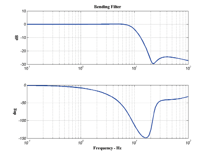
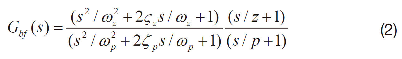
The bending filter takes a form of a low-pass notch filter whose ty pical frequency response is shown in Fig. 9 A third order bending filter of Eq. (2) is applied to the KSLV-I upper stage.
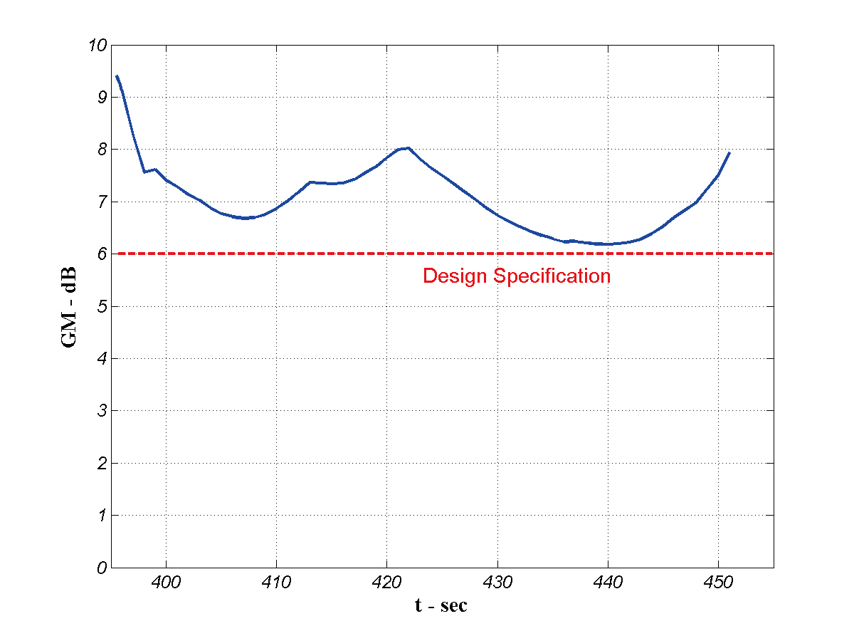
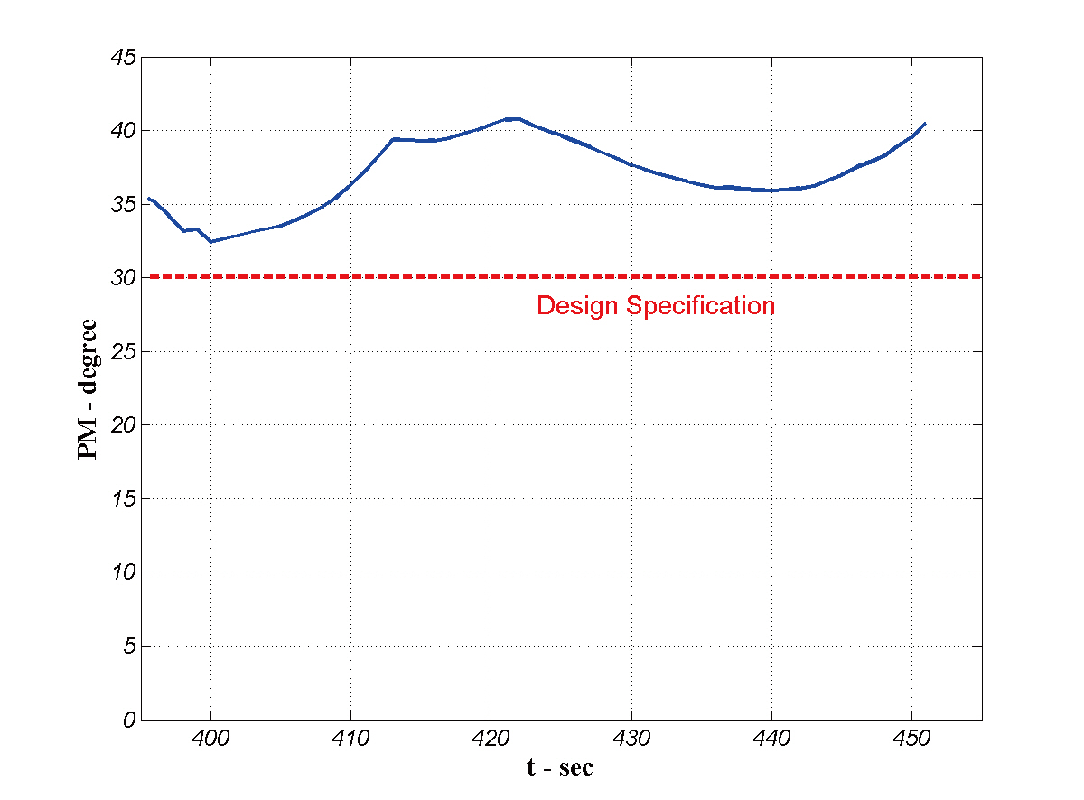
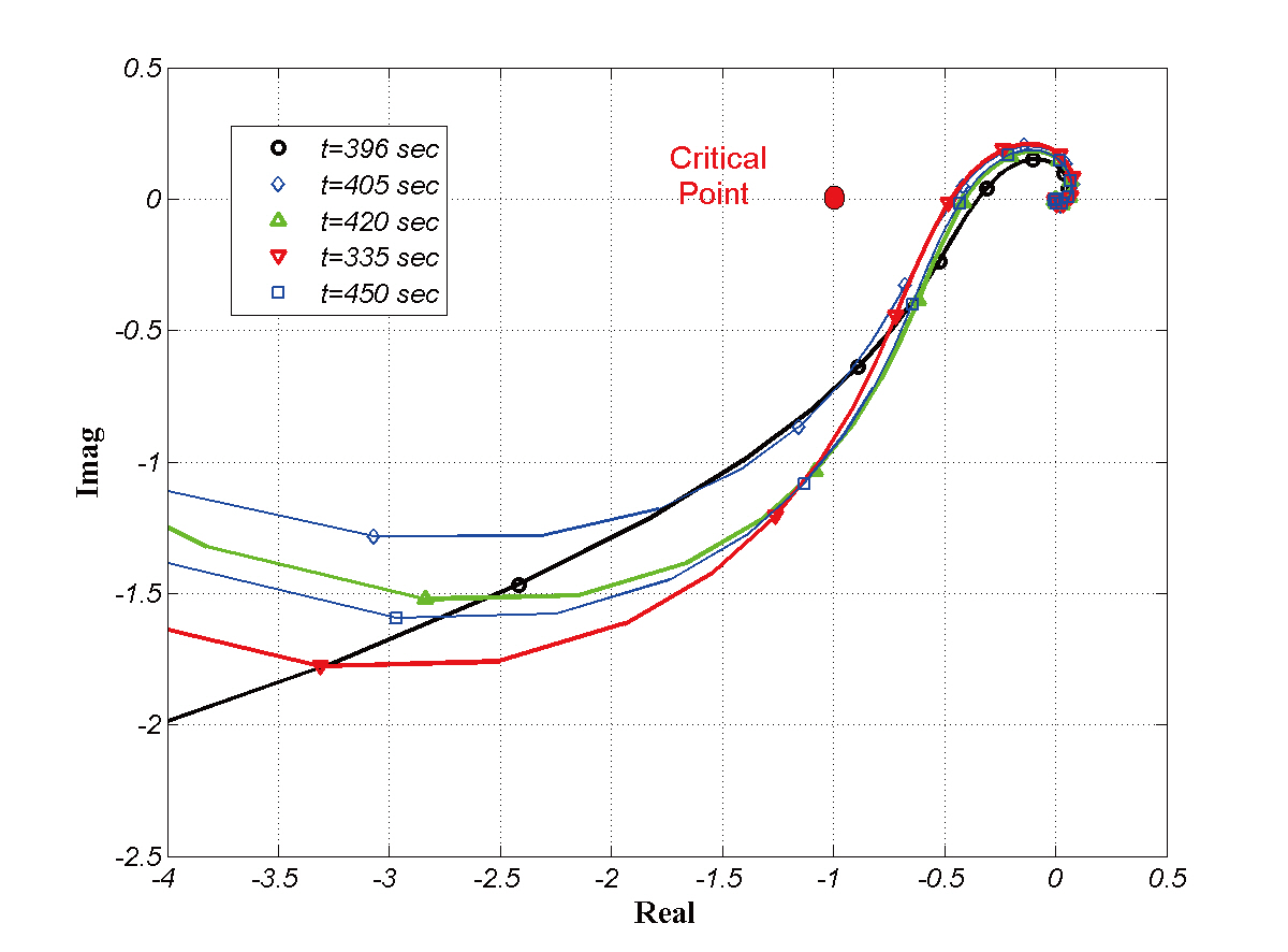
Figures 10-12show the TVC controller design results of the KSLV-I upper stage. Figure 10 shows the Nyquist plot during the thrusting phase. It can be easily seen that the frequency responses of the TVC control loop remain at a safe distance from the critical point, -1+0j. The corresponding stability margins in Figs. 11 and 12 satisfy the design criteria.
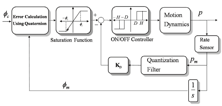
A block diagram for the RCS controller design (Sidi, 1997; Wie, 1995) is shown in Fig. 13 Schmidt Trigger ON/OFF controllers are designed for RCS controller of KSLV-I upper
stage.
A hysteresis parameter
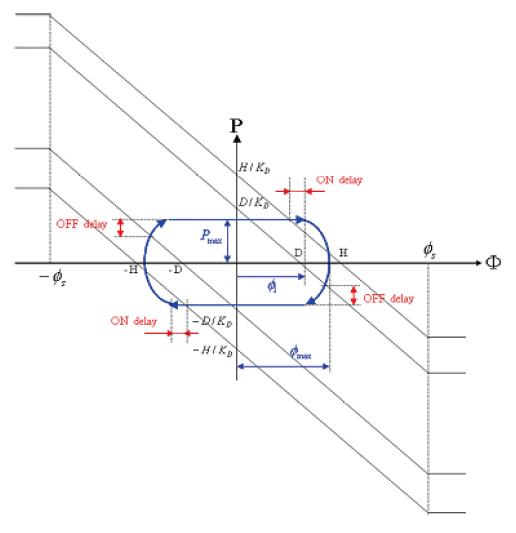
motions as in Fig. .14 In the figure, the effect of ON/OFF time delays is included. Note that the time delays make the limit cycle bigger.
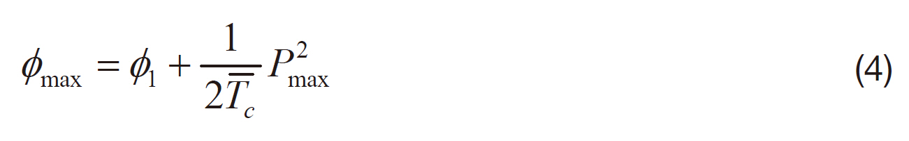
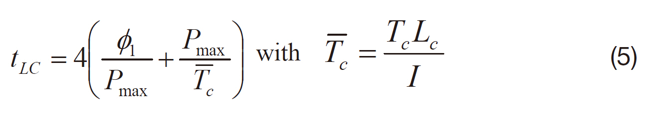
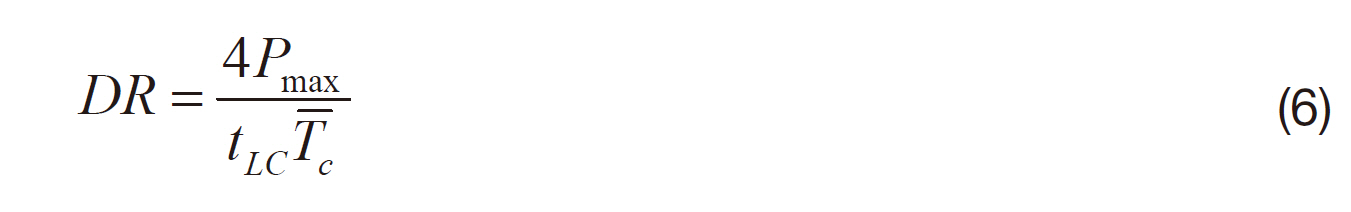
The major properties of limit cyclic motion can be represented as functions of control parameters and time delays as follows. (Sun et al., 2009)
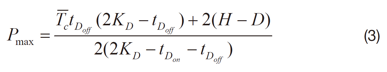
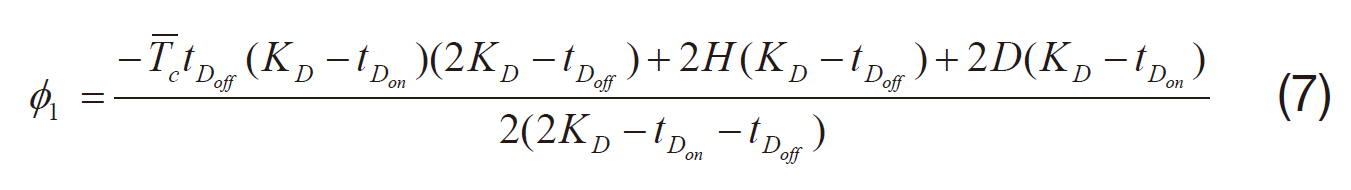
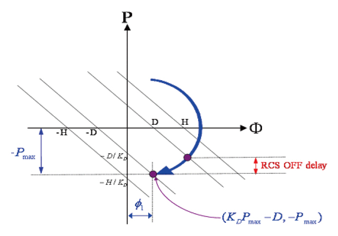
When designing RCS controllers, it is important to stabilize the limit cycle for all operating times. A typical case in which the limit cycle can be broken is shown in Fig. 15,where the excessive angular motion directly touches the opposite dead-band without any intermediate OFF operation due to
large OFF time delay and small dead-band. This case causes an increase of the duty ratio and excessive consumption of nitrogen gas.
To avoid such a harmful case, the control parameters must satisfy the following constraint:
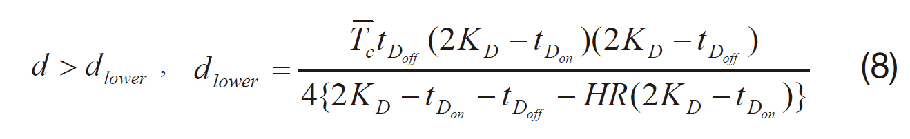
where
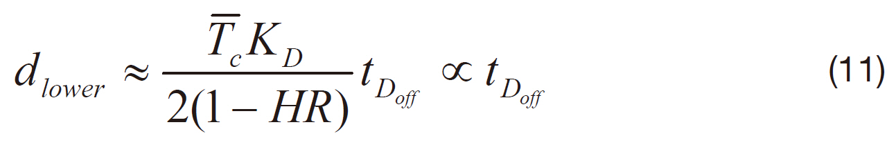
The lower limit of the dead-band is proportional to the OFF time delay, which means that the time-delay margin can be guaranteed by making the dead-band sufficiently large. On the other hand, the larger the dead-band is, the larger the attitude error becomes on the limit cycle. A trade-off between stability and performance may exist. Therefore, it is necessary to design the dead-band large enough within the range satisfying the attitude error specification.
The specifications applied for RCS controller design of KSLV-I upper stage are as follows:
- Minimum ON pulse - ? 0.1 sec
-Limit cycle period ? 6.0 sec
- Duty ratio ? 5.0 %
-Time-delay margin ? 6 times of nominal RCS time-dealy
- Angle error ? 1.0 degree for pitch and yaw axes ? 3.5 degree for roll axis
-Rate error ? 0.5 deg/sec for pitch and yaw axes ? 1.5 deg/sec for roll axis
The RCS ON/OFF time-delay is assumed as 0.05 seconds. Tables 1 and 2 show the results of RCS controller design where the ratio
[Table 1] Pitch and yaw reaction control system controller design result
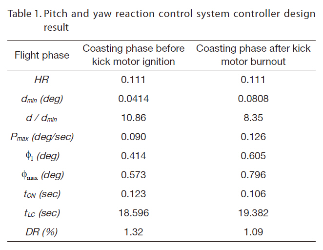
Pitch and yaw reaction control system controller design result
[Table 2] Roll reaction control system controller design result
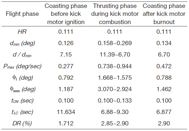
Roll reaction control system controller design result
each flight phase, the controller parameters remain constant regardless of system variations. It is easily seen that all design specifications are satisfied. The minimum time delay margin is 6.7, which suggests that the system remains stable even though the RCS time delay increases as high as 0.335 seconds.The maximum duty ratio is about 3%. It is noted that the duty ratio may increase proportionally to external disturbances.
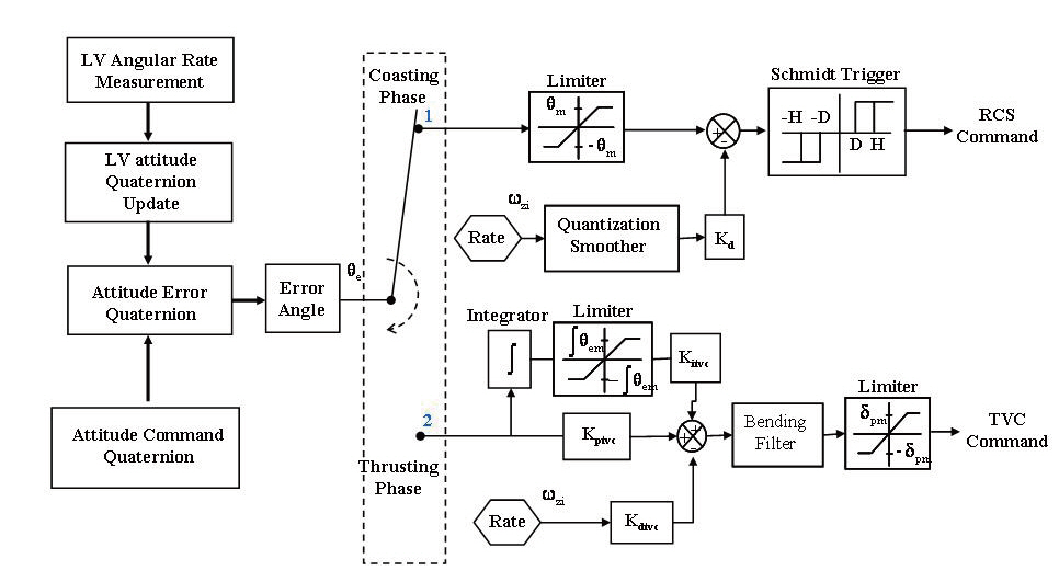
3.3 Onboard attitude control algorithm
An onboard attitude control algorithm for the KSLV-I upper stage is configured by Fig. 16 The three-axis angular rates measured by inertial measurement units enter the autopilot as input. Based on the rate measurement, attitude errors are computed via quaternion calculations. The quaternion feedback structure advantageously handles unwanted large errors which may result from the first stage flight or severe external shocks. A switching logic operates to select a current controller between the TVC controller and the RCS controller according to flight phase change. After passing the switching box, the lower part shows the TVC controller block
and the upper part shows RCS controller block. The bending filter and quantization filter are implemented in a discrete form. The TVC and RCS commands are generated every 0.01 seconds.
4. Stability and Performance Test
4.1 Test setup of KSLV-I upper stage
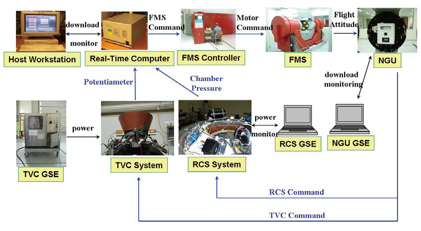
After the TVC and RCS hardware are integrated into the upper stage, the stability and performance of the attitude control loop of the KSLV-I upper stage is verified synthetically in a system level. First of all, nonlinear simulations are accomplished for parametric variation cases by six degrees of freedom (6-DOF) program code. And then, hardware in the loop (HIL) tests are prepared. Figure 17 shows the configuration of KSLV-I upper stage HIL tests. (Park et al.,2005; Sun et al., 2006, 2007)
In HIL tests, the attitude controllers are implemented into the navigation and guidance unit (NGU) which acts as the onboard computer. The NGU includes the navigation and guidance module as well as inertial sensors. The 6-DOF
simulation code is loaded onto a real-time computer system(RTS) which calculates the translational and rotational motions of KSLV-I in real time. A flight motion simulator(FMS) provides three axis rotational motions to the NGU according to real time calculations of flight motion. The NGU which is mounted on the inner axis plate of the FMS measures the inertial attitudes, and then generates the corresponding guidance and control commands. The TVC and RCS operate according to the NGU commands. The nozzle angles deflected by the electro-hydraulic TVC actuator are measured by potentiometers and fed back to 6-DOF program in RTS. The actual thrusting forces of each RCS nozzle are measured by pressure sensors and fed back also to 6-DOF program. By propagating the flight dynamics with the measurements, a closed-loop system is implemented on the ground.
The HIL test program in the RTS contains, in addition to the simulation modules for vehicle dynamics, several interface modules including a high speed networking module for FMS operation, a low speed networking module for initial setup, and analog and discrete interface modules for data processing. An IEEE488 interface is set up for device initialization. A ScramNet interface is set up for high speed communication with the FMS. AD and DA interfaces are set up for communication of TVC commands, potentiometer measurements, and RCS chamber pressure measurements. A 64-bit discrete parallel interface is set up for communication of RCS ON/OFF commands and separation events control.The integration time step of the RTS program is 0.001 seconds.
4.2 HIL test condition of KSLV-I upper stage
The HIL tests of the KSLV-I are basically accomplished under a nominal flight condition which does not include any disturbances. Based upon the nominal flight condition,perturbed flight conditions are defined to evaluate variations in stability and performance of the system. Here, three-sigma perturbations and worst perturbations are considered for KSLV-I upper stage as in Tables 3 and 4.
For the HIL tests of the upper stage, the corresponding flight motions are simulated from lift-off until mission-end.The tests do not start at stage separation, but start at liftoff in order to cover the errors which result from the first stage flight region. The control systems of the first stage are mathematically simulated in RTS.
4.3 Typical HIL test results of KSLV-I upper stage
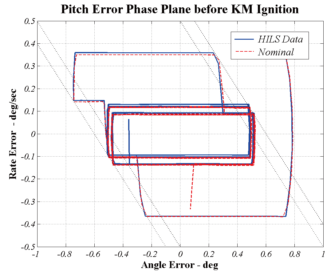
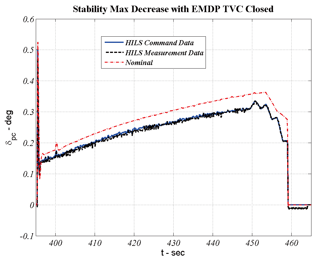
Figures 18-21show typical HIL test results under a stability decreasing condition. For the convenience of comparison,the HIL test results at the nominal flight condition are
[Table 3.] Perturbed flight condition in terms of stability reduction during thrusting phase
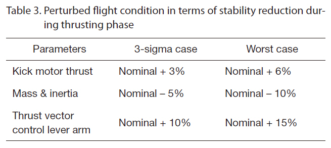
Perturbed flight condition in terms of stability reduction during thrusting phase
[Table 4.] Perturbed flight condition in terms of stability reduction during coasting phase
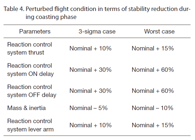
Perturbed flight condition in terms of stability reduction during coasting phase
included in the figures. It can be easily seen that the attitude control loop of the KSLV-I upper stage is very stable and the attitude controllers perform well for the flight condition.
5. Flight Test Results of KSLV-I
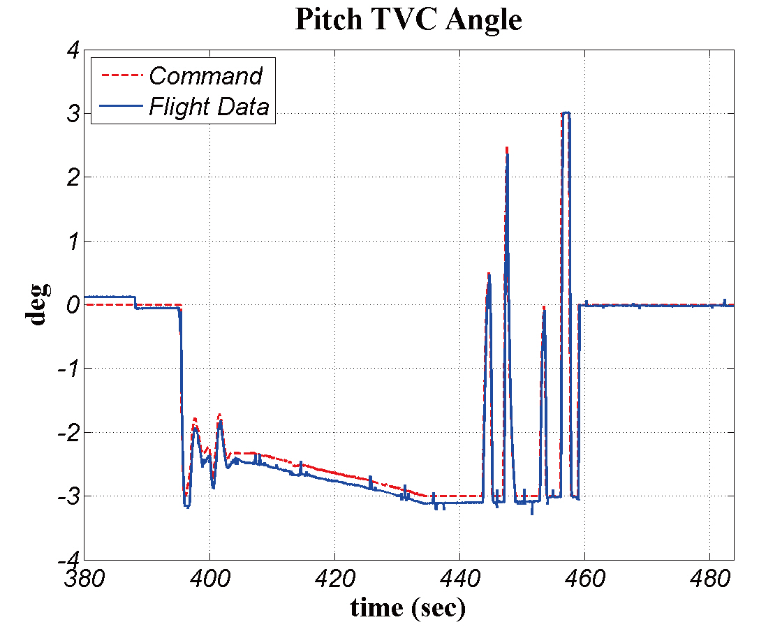
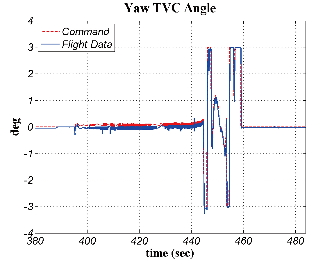
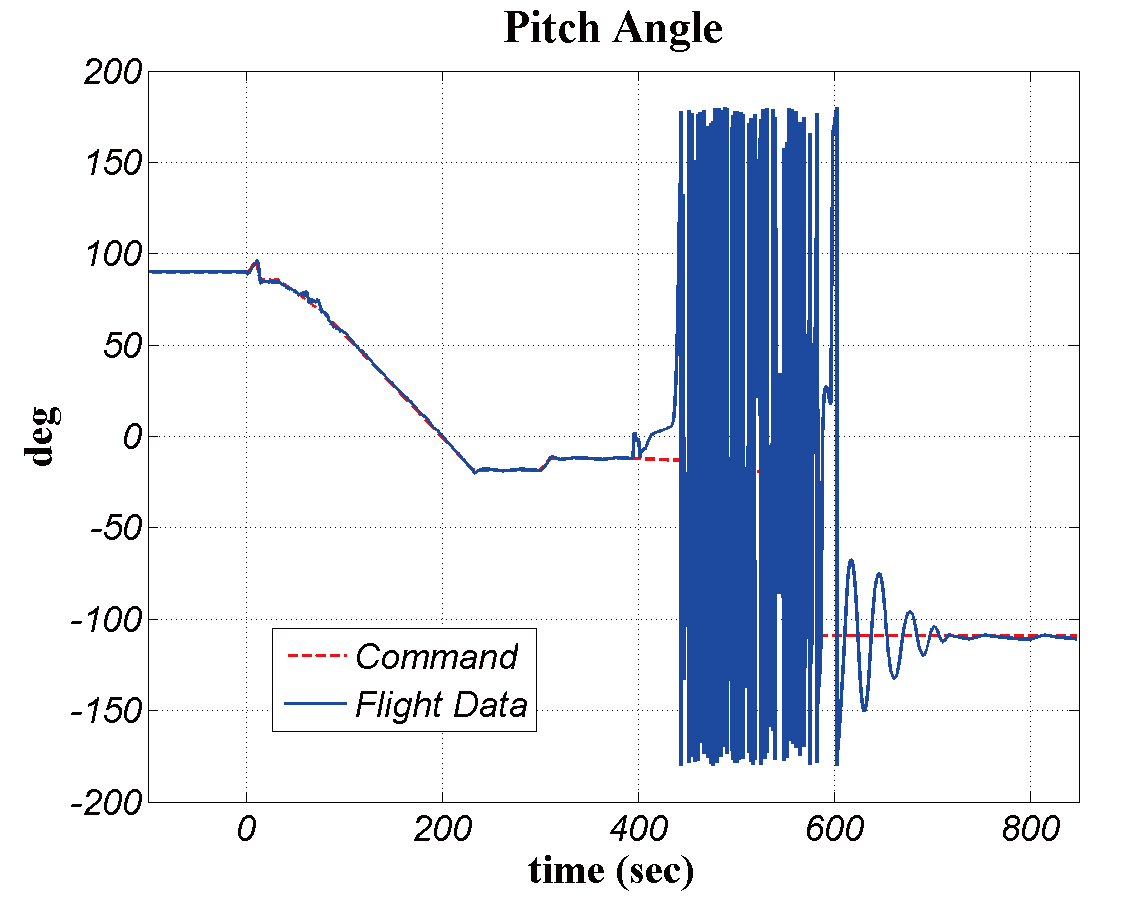
The first flight test of KSLV-I was conducted on August 25, 2009. Although the KSLV-I was successfully launched into the sky, it failed to deliver its payload to the target orbit.There occurred abnormal fairing separation before stage separation. Only one half of the fairing was separated from the KSLV-I, and the other half remained on the KSLV-I.Severe weight addition prevented the upper stage from achieving enough velocity necessary for entering the target orbit. Severe weight unbalance with respect to pitch axis induced an excessive TVC deflection angle over the design limit during the kick motor combustion period. From the moment the TVC design limit was exceeded, the upper stage began to tumble without brake. Figures 22-24show the flight data of the upper stage attitude control, where large pitch TVC deflections were demanded in order to compensate for the large mass center offset during the thrusting phase, and the pitch TVC deflection angles were saturated at about 434 seconds. At that time, the pitch attitude error began to rapidly increase. And the upper stage entered a tumbling motion.
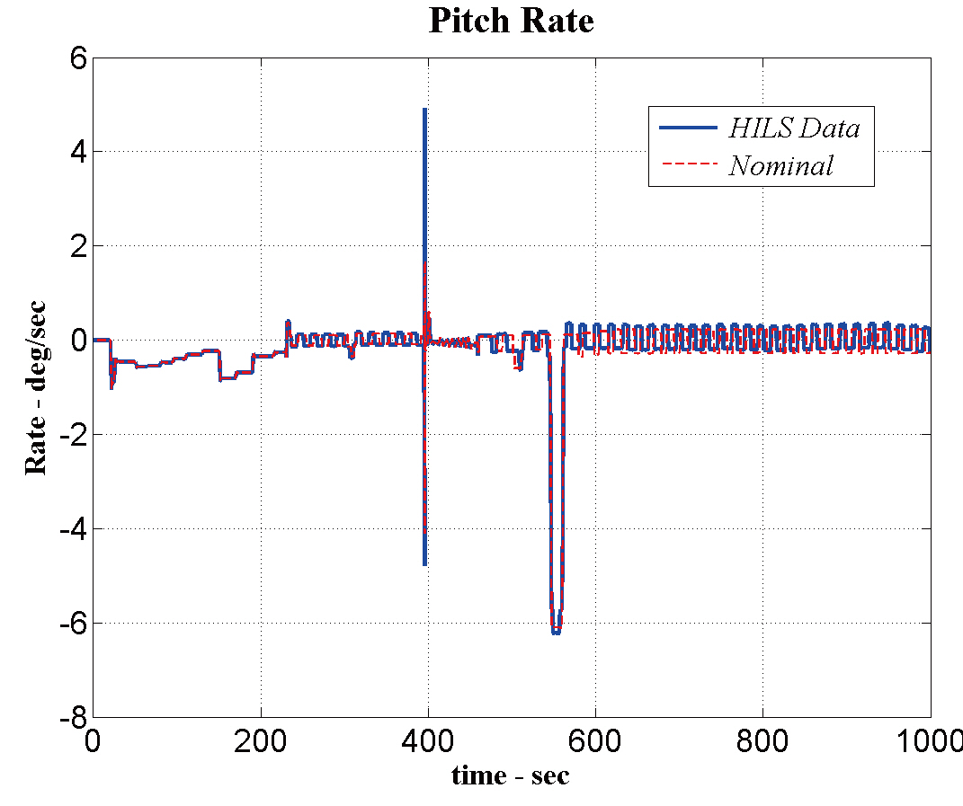
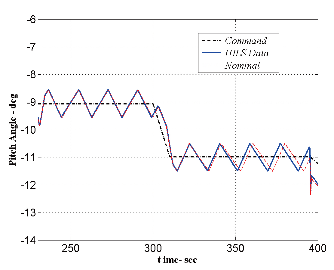
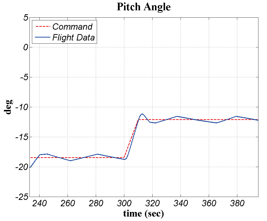
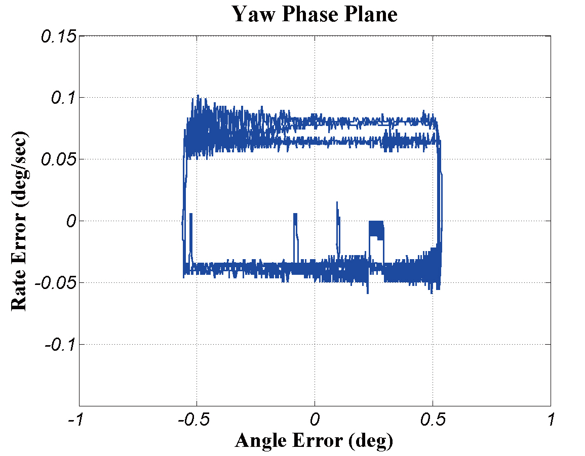
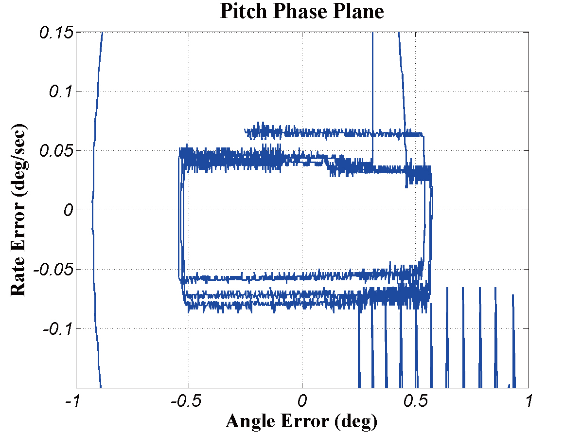
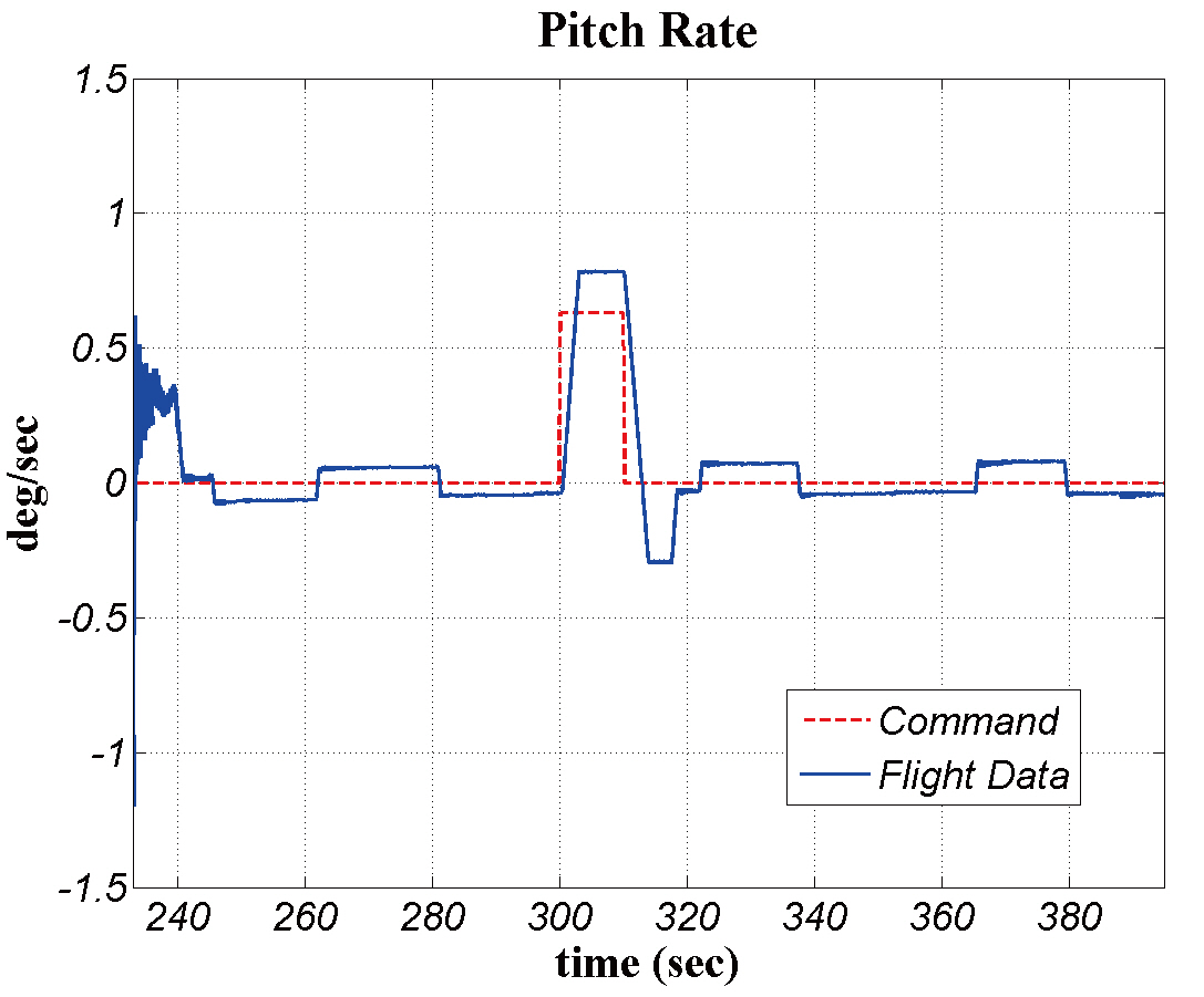
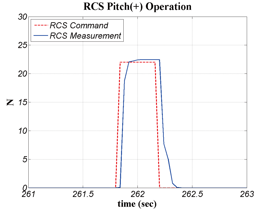
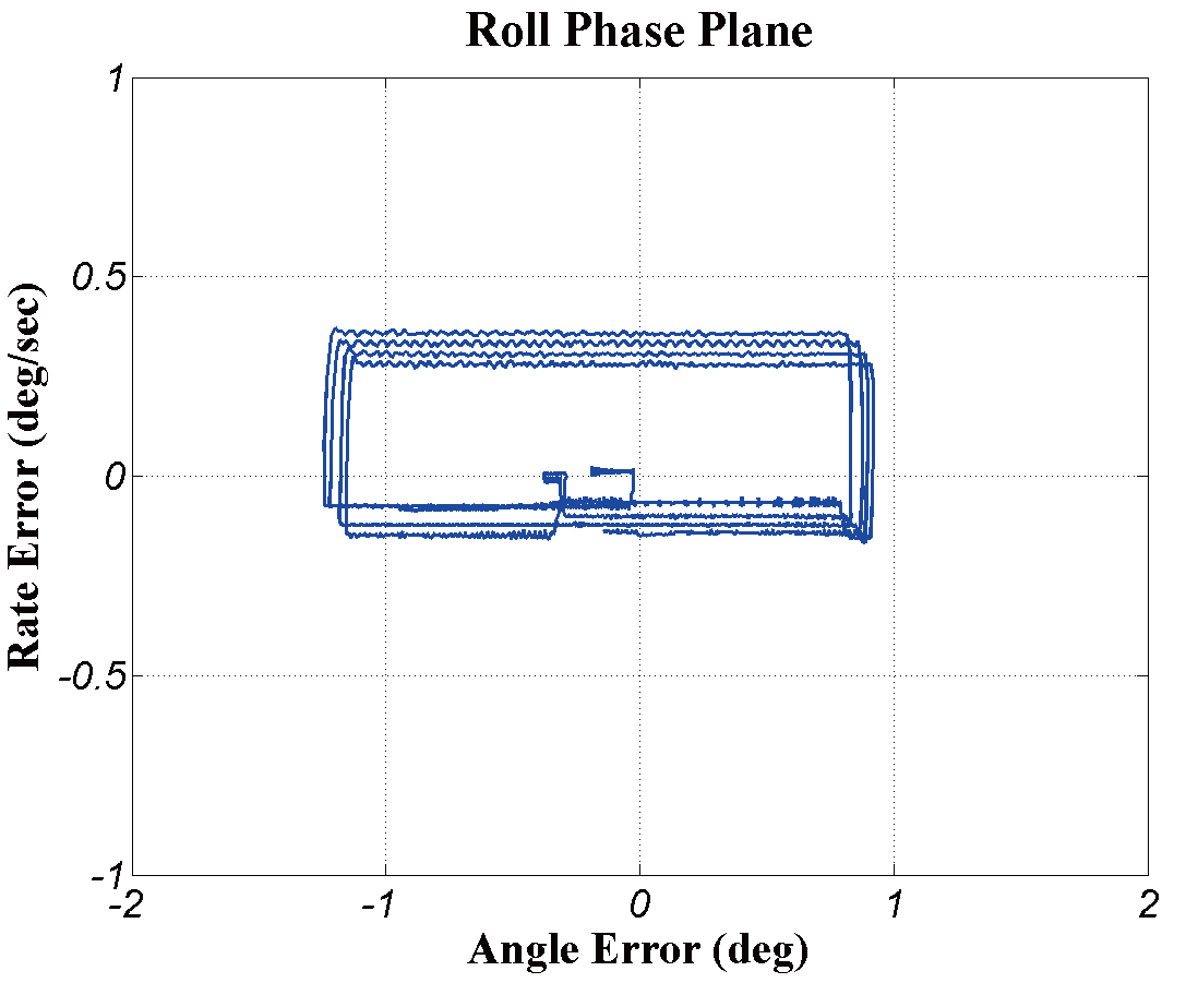
Nevertheless, the attitude control system of the KSLV-I upper stage fulfilled its own roles even under the abnormal flight condition. Figures 25 and 26 show that the pitch angular rate and the pitch angle were excellently controlled by the RCS until kick motor ignition. Figure 27 shows a typical ON pulse duration of pitch RCS at the same flight phase. The ON pulse sustained its status longer than 0.35 seconds which is three times larger than the designed value.To compensate for the increased moment of inertia, the RCS commands became longer than predicted. Figures 28-30show the RCS limit cyclic motions within specified error bounds. In addition to the RCS controller, the TVC controller also performed very well until saturation. Consequently,all attitude controllers of the KSLV-I upper stage performed well and satisfied the accuracy specifications even under the abnormal fairing separation. It can be said that the stability and performance of the KSLV-I upper stage was verified at this first flight test.
This paper introduced the attitude control systems for the KSLV-I upper stage. Attitude control design was accomplished for a thrust vector control system and a reaction control system. The TVC and RCS attitude controllers were designed to have enough stability margins. Stability and performance of attitude controllers were tested via HIL tests. The HIL tests were conducted for perturbed flight conditions as well as a nominal flight condition. The HIL test results exhibited that the attitude control loop of the KSLV-I upper stage is very stable and the attitude controllers perform well for all flight conditions.
On August 25, 2009, the first flight test of KSLV-I was conducted using the onboard attitude controllers designed in this paper. The flight test results show that all attitude controllers of KSLV-I upper stage performed well and satisfied the accuracy specifications even in case of abnormal fairing separation.