One of the leading trends of the current computing system era is distributed computing. Ubiquitous and World Wide Web are the keywords and representative embodiments of distributed computing. In the information-oriented society and the current ubiquitous computing era, it is both impossible and unnecessary for a user to integrate all his or her needed information into one or several computer systems, because distributed technology is well organized and makes it easy to handle the distributed information. The same trend is found in embedded systems and the simulation field. For example, a sensor network is a well-known type of distributed system that is connected via a wireless and synchronous connection. The same phenomenon is found in simulations in the satellite development and control industry area (Dutch Space 2008, Koo et al. 2009). In the simulation field, it is a general practice to configure a single simulation environment by including multiple simulators, each with a specific purpose, for achieving one simulation goal. Virtual spacecraft reference facility real-time bench design (Dutch Space 2008) well describes this mechanism. There are many simulators and there are also many front-end applications to connect to each other. This is referred to as distributed simulation. A distributed simulation has the benefit of enabling more flexible system control and configuration, and achieving nice load balancing among the distributed systems. But there is no global standard for distributed simulation methodology in the satellite simulator development field. The only nominated technology is the European Space Agency’s (ESA) simulation model interface (SMI)/simulation model portability (SMP) standard. The following chapters describe the software simulator being developed by the Korea Aerospace Research Institute (KARI), the design mechanism for developing distributed simulation environment complying with ESA SMI/SMP standard, and design verification through the demonstration program.
GenSim is an abbreviation for generic simulator, and is a software simulator of satellite and its components such as on board computer (OBC), MIL-STD-1553B data bus and payload (P/L). The main application of GenSim is a validation tool for satellite flight software. The design of GenSim was inspired by the ESA simulation infrastructure for the modeling of satellite SIMSAT and EuroSim. Generally, satellite software simulators have requirements for flight software validation (Eickhoff 2009), such as software debugging capability on simulation via gnu debugger (gdb) or WindRiver debugger (WDB), interfacing capability to the simulated satellite component, and real hardware satellite component for avionics test campaign,as well as real-time simulation behavior for adapting the interface between real hardware and simulator.
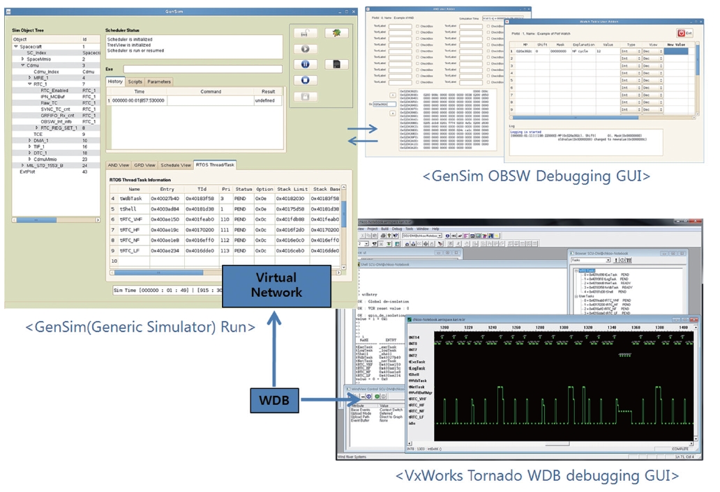
First, to implement the software debugging capability,
particularly for gdb on GenSim, the management of the simulation kernel to match the timing characteristics of simulation time between GenSim and processor emulator was applied. Also, to support WDB, which is the debugging utility of WindRiver Tornado, a virtual network and SMC 91C111 network simulation was performed on GenSim, as shown in Fig. 1 (Koo 2010). Finally, GenSim has real time operating system (RTOS) awareness for real-time executive for multiprocessor systems (RTEMS) and vxWorks. So, GenSim can identify the thread/task and stack information of the RTOSs, as shown at the left of the GenSim window in Fig. 1.
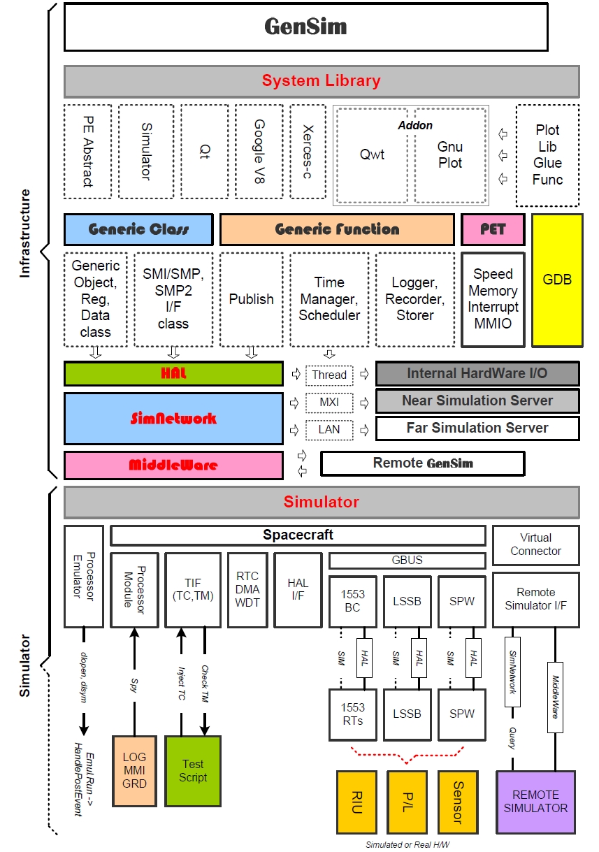
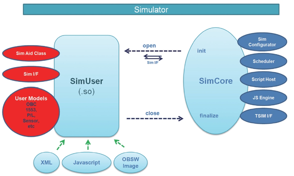
GenSim consists of a simulation infrastructure part and a simulator model part. The simulation infrastructure part provides the functionality of a simulator engine,such as simulation scheduler and script manager. It is the so-called simulator kernel. The simulator model part is a library of a user-specific simulator model, which is written in a programming language such as C, C++ or Fortran. Each of the parts exists independently, but the parts are dynamically linked with each other when the simulation infrastructure part (SimCore) loads the simulator model part (SimUser), as shown in Fig. 2. ESA SMI/SMP standard is the simulation modeling standard (ESA 2003, Koo et al. 2010) and is adopted in ESA SIMSAT and EuroSim. GenSim also adopts the ESA SMI/SMP standard. A simulator model that is in accordance with ESA
SMI/SMP standard is reusable at ESA SMI/SMP compatible simulation kernel such as ESA SIMSAT, EuroSim and GenSim (Koo et al. 2010).
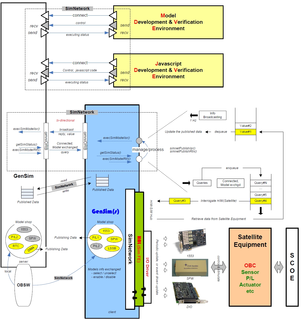
As shown in Fig. 3, GenSim has been designed to interface with external simulation infrastructures, such as a near or far simulation server and remote GenSim. It is necessary to connect with remote GenSim due to the requirement to have a software simulator interface with both the simulated model and the real hardware component. Managing and integrating the simulated models of a satellite and its components is quite complex, so it is often a heavily loaded job when all simulation activity, such as running pure simulated models and interfacing real hardware, is done in a single-computer environment (Koo et al. 2011). Because a software simulator is supposed to be used not only in flight software logic validation,but also in satellite integration test such as electrical test bench, GenSim is designed to interface with real satellite components or I/O board, which will be interfaced with the real satellite component as shown in Fig. 4.
The distributed simulation infrastructure on GenSim is dependent on a hardware abstraction layer (HAL), a simulated network (simNetwork) and middleware, such as a common object request broker architecture (CORBA). HAL is necessary for managing real hardware I/O board or satellite component from simulator, and will be implemented as simulator front end (SimFE) later. In this paper,information of simNetwork design and middleware interface to cooperate with simNetwork is presented. GenSim can be configured with a pure simulated model, real hardware of satellite component or I/O board during on board software (OBSW) execution. Distributed simulations and experiments are often necessary because the experiment environment is harsh sometimes due to noise, heat, the close proximity of heavy equipment and vibration. So if the data acquisition node on the validation bench can be separated from the mother simulation bench table, the operator can safely perform the validating process while the data acquisition node is interfacing with hazardous equipment. simNetwork was designed to achieve these purposes (Koo et al. 2011), and the implementation contents are presented on this paper.
The main purpose of simNetwork is to expand the simulation capability of GenSim to the external space of a single computer. Through simNetwork, local GenSim can manage the remote simulation resources on remote GenSim, even the real hardware of a satellite component or I/O board. The development of a simulation model on GenSim is based on the ESA SMI/SMP standard. Accordingly, simNetwork is implemented to comply to the ESA
SMI/SMP standard, since the remaining parts of simulator models that are connected with simNetwork follow the ESA SMI/SMP standard. simNetwork is cooperating with SMI published service and data on the remote simulator model part. Simulator model on the remote side GenSim can be registered to the model shop on local GenSim, then local GenSim can access it seamlessly, even though the simulator model is resident in the remote side and connected via middleware. In Fig. 4, the simNetwork configuration of GenSim is shown.
simNetwork is one of the SMI protocols on the GenSim infrastructure, and can be summarized as an interface and communications rule between local and remote GenSim for interfacing with simulating data acquisition and commanding, invoking remote side simulation service calls, like the remote procedure call concept in Windows.simNetwork uses omniORB CORBA portable object adapter (POA) middleware service (Birman 2005) as
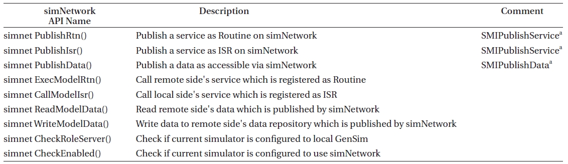
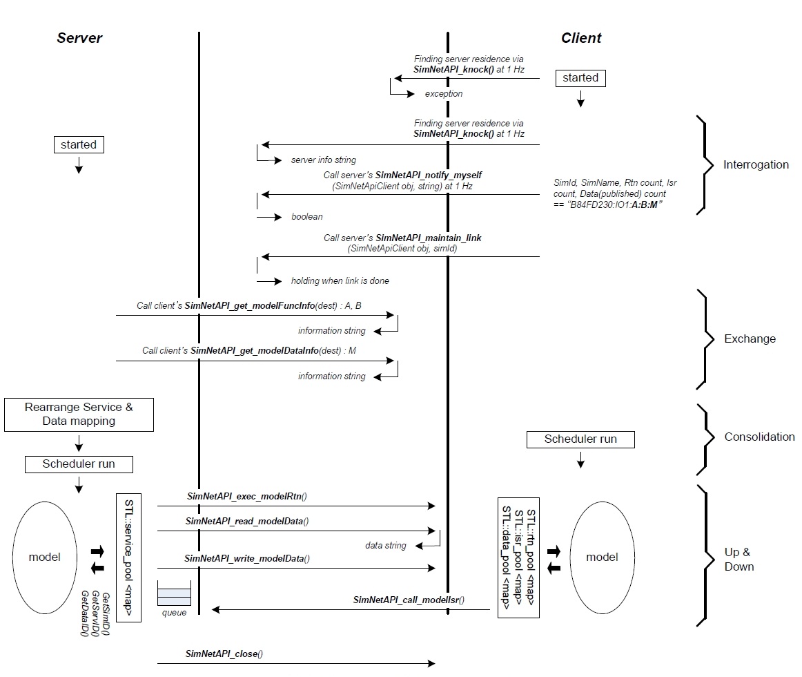
a physical communication channel. In the above physical communication channel, simNetwork protocol layer provides multiple GenSim instances with a transparent simulation connection so that the simulation kernel can seamlessly access the remote simulation resource. simNetwork protocol consists of 4 steps, Interrogation (I), Exchange (II), Consolidation (III), and Up&Down (IV), as shown in Fig. 5 (Koo et al. 2011). Also, to provide a rich set of simNetwork protocol functions that are compatible with the ESA SMI/SMP standard, simNetwork application program interfaces (APIs) listed in Table 1 are developed.
Connecting two GenSims via simNetwork, one GenSim is called a server if it has been configured to take the role of charging the dominant scheduler owner. The other GenSim is called a client if it has been configured to take the role of providing only partial I/O simula-
[Table 1.] Summary of simNetwork API.

Summary of simNetwork API.
tion or actual I/O handling. At the interrogation step, the client first searches for the server to initiate a link between the server and itself. This is performed by omniORB API. Thanks to the omniORB API, the client can identify whether the specified server exists on the omniORB POA service layer. This search is attempted regularly,such as at 1 Hz frequency, until client detects the server’s existence on the omniORB POA service layer. If the client detects the server’s existence, the client will try to provide some information about what services to be reported to the server. This is also performed regularly, e.g. at 1 Hz. SimNetAPI_notify_myself() on simNetwork is used for this purpose. Client attempts this API repeatedly until server accepts this connection. On the server side, if everything is ok and ready to allow a possible client connection attempt, the server enables simNetwork connection service and will permit the connection from the client as described above. If the trial connection is permitted, SimNetAPI_notify_myself() can give the information of client such as SimID, SimName, Rtn count, Isr count and data count. This is delivered as a string; for example it might be “B84FD230:IO1:3:4:9”. It means the SimID is 0xB84FD230, SimName is “IO1,” and it has several services as Rtn services(3), Isr services(4), and data interface(9). All services of Rtn and Isr are directly matched with the SMI services which are published by SMIPublishService() on ESA SMI/SMP standard. All data is directly matched with the SMI data that is published by SMIPublishData(). After reading the information given by SimNetAPI_notify_myself(), server recognizes the basic characteristics of client.
Now, the server can make an inquiry to client to retrieve the detailed information of the basic characteristics acknowledged by SimNetAPI_notify_myself() in the prior step. Server invokes SimNetAPI_get_modelFuncInfo() to get the detailed information about the acknowledged Rtn and Isr services from the client. For the response, client sends feedback as a string in the format of “ObjectID:ObjectName:ServiceName:Service:GenericObj:ServiceParameter.” Also, the information of the data interface on client is acquired via SimNetAPI_get_modelDataInfo(). All of this information is stored and registered in the simulation kernel on the server (local GenSim) and can be used during simulation. Once registered, all Rtn, Isr services and data from remote GenSim are available in local GenSim’s kernel operation.
Server (local GenSim) is active and client (remote GenSim)is passive for the role of managing the simNetwork communication. In this step, server merges its service pool with the client’s Rtn and Isr service information delivered by simNetwork protocol. Client’s data interface is also added or merged with server’s data pool. Considering this mechanism, merging is like remapping. Actually, the server simply remaps the newly added service into the presented service pool. After remapping, it is ready to start or run the scheduler to initiate the simulation.
In the previous steps, all information required for calling or referencing client’s service and data was exchanged.In this step, actual cross service and data utilization is done over simNetwork. So this step corresponds to the real working phase, as its name, Up&Down, implies.Just like a carpenter goes up and down a ladder to fix a house, during simulation a command signal occurs on simNetwork between server and client. Server can invoke a service resident in client via the SimNetAPI_exec_modelRtn() method. In addition, a server can read or write a data resident in client via SimNetAPI_read_modelData()and SimNetAPI_write_modelData() method. Client can call a service resident in the server via the SimNetAPI_ call_modelIsr() method if the service call request is accepted by server. This is called an interface service routine (abbreviated ISR, like interrupt service routine). At the server’s view, it is a seamless operation. All services that are supposed to run during simulation will run, whether simNetwork is used or not. The only difference is the latency (or delay) of communication when a service is called via simNetwork based on omniORB and simNetwork protocol. A detailed analysis shall be performed to identify the effect of the latency caused by simNetwork on reliable simulation operation.
6.1 Demonstration configuration
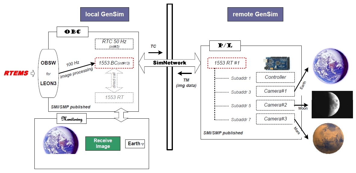
To validate the performance of simNetwork, a demonstration system is designed. In this demonstration system, MIL-STD-1553B data communication system is modeled and divided into a bus control (BC) part which is resident in local GenSim and a remote terminal (RT) part which is resident in remote GenSim. This demonstration configuration is shown in Fig. 6. The simulation target of the MIL-STD-1553B device is the DDC ACE 1553 card family series.
Test OBSW is developed with RTEMS RTOS for leon3 processor. The Sparc leon3 cross compilation toolchain used in this demo development tool is GRTools, which was provided by Gaisler Aeroflex. The role of OBSW is to initialize the MIL-STD-1553B device and manage it to retrieve P/L image sensed data from MIL-STD-1553B
RT on the specific P/L component. As shown in Fig. 6, this demonstration system allocates RT number 1 to P/L, and P/L has 4 subaddresses for controllers, and 3 cameras.Each camera holds different images, such as Earth, Moon, and Mars. If OBSW requests MIL-STD-1553B BC to receive a specific image from the P/L simulator model via simulated MIL-STD-1553B data bus, a command is delivered to the P/L simulator model that is resident in the remote side via simulated MIL-STD-1553B data bus model through simNetwork. Once receiving the command, the remote side’s P/L simulator model prepares appropriate raw image data, which is to be delivered to OBC later. Subsequently, OBSW retrieves the specific image data from the P/L simulator model via the simulated MIL-STD-1553B data bus through simNetwork. OBSW, OBC model and P/L model are not aware of the existence of simNetwork because simNetwork seamlessly connects multiple GenSims into a single simulation environment.
While OBSW brings the specified image from the P/L simulation model on a remote GenSim at 100 Hz via MIL-STD-1553B data bus simulation that is connecting with local GenSim and remote GenSim through simNetwork, a memory buffer in OBC holds the received image data.
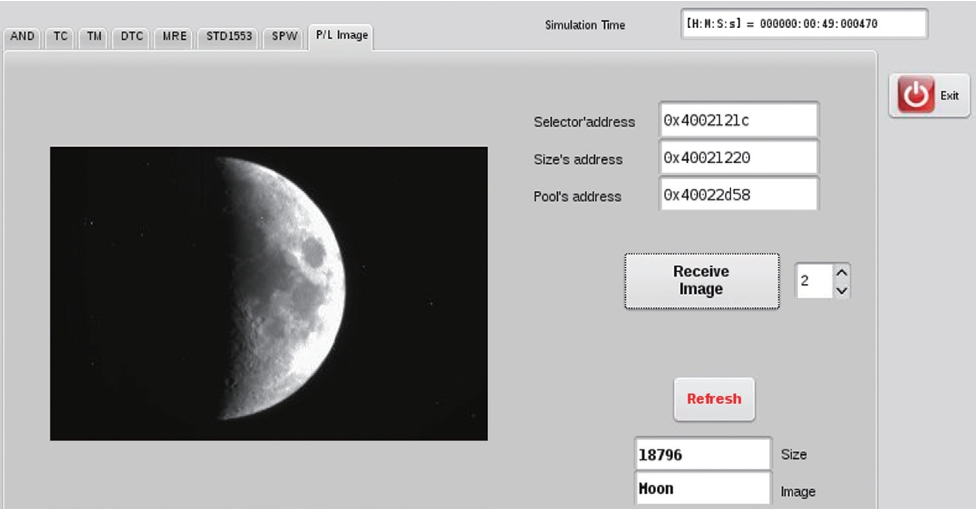
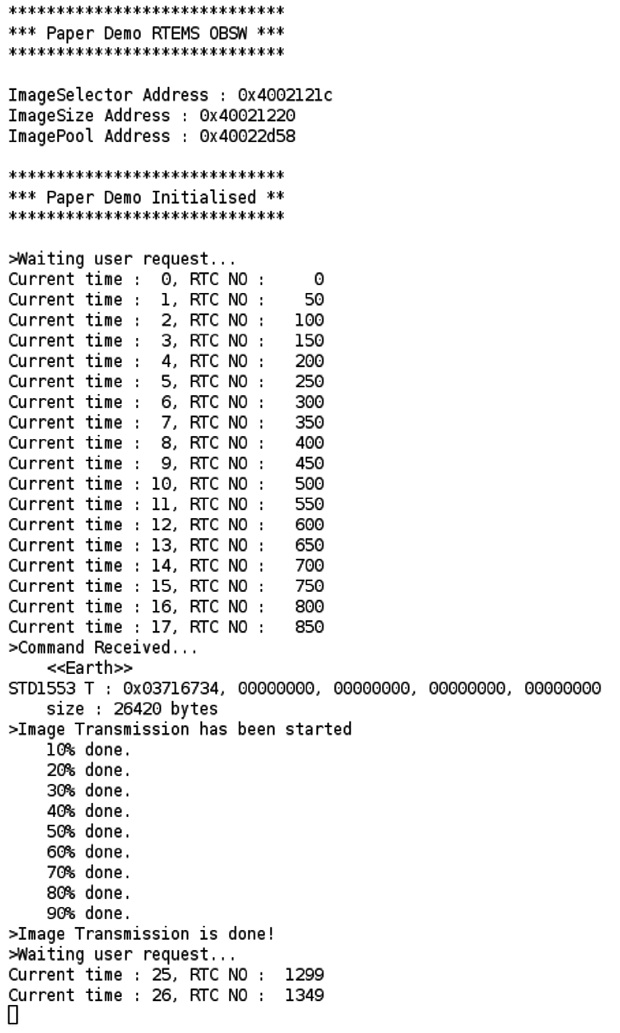
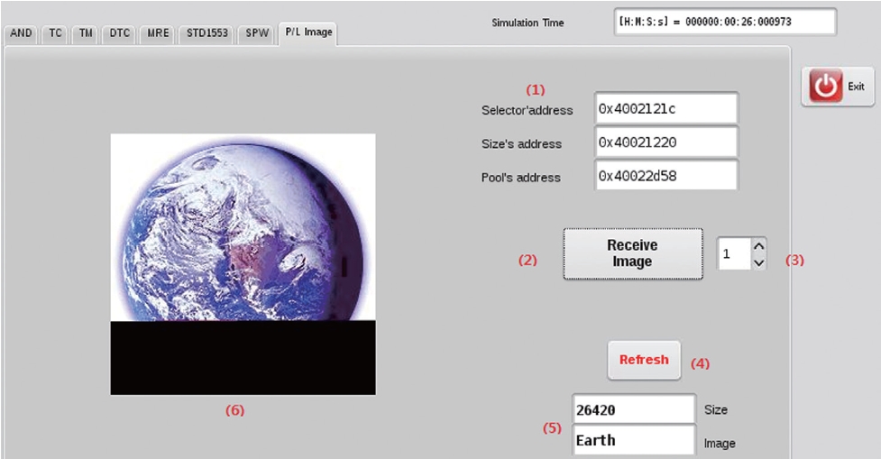
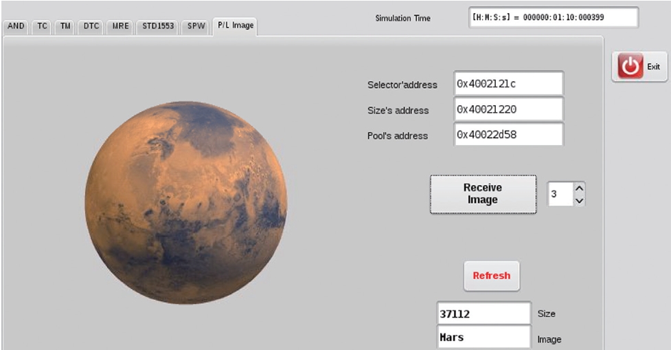
Once the simulator is set to run mode, OBSW is loaded and initialized automatically according to the simulator configuration information file (.xml). As shown in Fig. 7, in this demonstration system OBSW leaves some informative messages to show the reference addresses of important OBSW variables that will be used at simulator view, as was used in Fig. 8. Then, the operator of this demonstration system enters these references of important variables to (1) in Fig. 8 to give the information to the simulator so that the simulator can refer to the information when a button is clicked. When the operator clicks (2) in Fig. 8, OBSW’s selector value (default: 0, no action) is changed to the value of (3) in Fig. 8 by the simulator. Once the selector value is changed, OBSW starts the new image transmission process. The operator can check the transmission status by clicking (4) in Fig. 8 at any time during the image receiving process. The target image’s size and name is then displayed at (5) in Fig 8, and the transferred image data is displayed at (6) in Fig.8.
As shown in Fig. 8, the Earth image is being transferred to the OBC simulation model from the P/L simulation model. Demonstrations for Moon and Mars images are also shown in Figs. 9 and 10. These picture image data are gathered from the remote simulator via simNetwork connection, and displayed with 100% data integrity. This is result is exactly the same as in the stand-alone simulation.
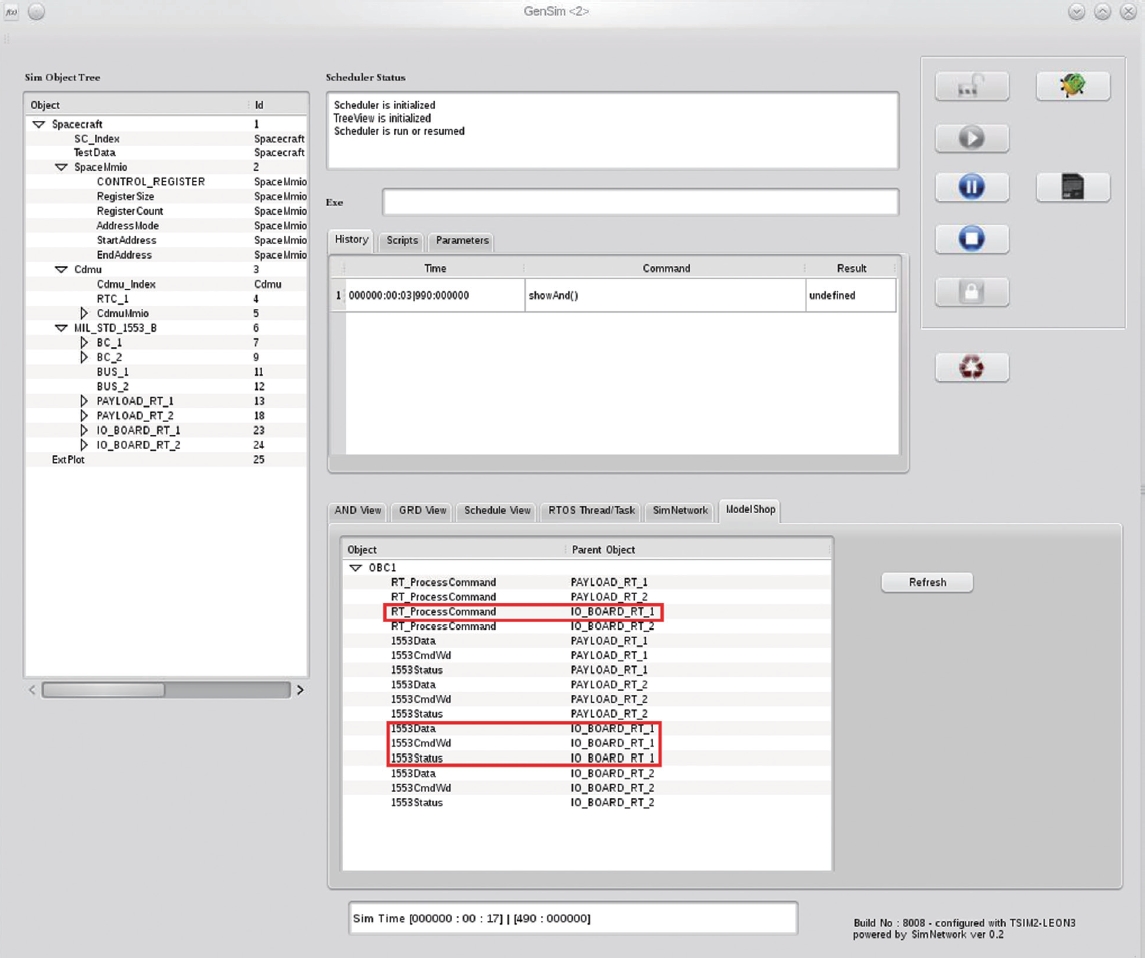
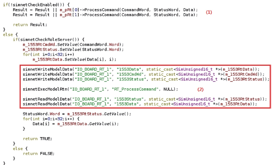
As shown in Fig. 11, the connected external simulation resources from remote GenSim via simNetwork protocol are displayed in the model shop window on the GenSim main window. In this demonstration system, the IO_BOARD_RT_1 simulation resource on remote GenSim is used for the payload I/O board simulation model that holds 1 controller and 3 images in data storage. In Fig.12,
an example simulation code on local GenSim to interface with the external resource on remote GenSim by using simNetwork is listed. (1) in Fig. 12 is executed when simNetwork is not used and local GenSim solely provides total simulation controllability. (2) in Fig. 12 is executed when simNetwork is used and the current instance of GenSim is on the local side, meaning that it holds the OBC simulation model part. In conclusion, with this code configuration, the internal MIL-STD-1553B data bus model is used when simNetwork is not enabled, while the external (remote) MIL-STD-1553B data bus model is used when simNetwork is enabled.
RT_ProcessCommand is an SMI published service (ESA 2003) from remote GenSim and is registered as a simNetwork Routine service using the simnetPublishRtn() API, which is compatible with the ESA SMI/SMP standard and is shown in Table 1. It means that the RT_ProcessCommand service can be called by an internal or external caller, i.e. a remote model over simNetwork. This service is a shell function of the ProcessCommand() function in (1), and actually calls ProcessCommand() after managing 1553 command words, status and data which are delivered by local GenSim via simNetwork.
GenSim is software simulation infrastructure and simulator that complies with ESA SMI/SMP standards. GenSim is capable of a distributable simulation infrastructure through the invention of a simulated network protocol, called simNetwork, and the performance is validated through the presented demonstration system. Less effort is expected when large and complex simulations of satellite modeling and test equipment configuration during various flight software development phases, such as unit test, integration test etc. (Eickhoff 2009) are requested.
The greatest benefit of simNetwork is its reusability, since simNetwork is compatible with the ESA SMI/SMP standard. For this reason, every model that was developed under ESA SMI/SMP standard can be used with the distributed GenSim, as demonstrated in this paper.
In future research, lag according to simNetwork will be performed. There are concerns regarding overall simulation performance, since there is some latency over the physical network connection between multiple distributed GenSims. Usage of high bandwidth is expected on simNetwork for the future simulation environment. For example, in this demonstration system, OBSW accesses the distributed MIL-STD-1553B data bus simulation model at 100 Hz, so latency analysis will be performed even though no abnormal behaviour was encountered during this demonstration simulation. The maximum bandwidth of simNetwork on various computer systems with diverse central processing unit clock cycles and operating systems shall be analyzed so that users can estimate simulation behavior under single simulation and distributed simulation through simNetwork.