MWNTs are reported to be always electrically conductive having an electrical conductivity reaching approximately 1.85×10³ S/cm [1]. Compared to the composites filled with carbon black or carbon fiber as conductive filler, polymer/MWNT composites show an extremely low percolation threshold values, owing to their ultrahigh specific surface areas and aspect ratio [2]. Therefore, their application to antistatic film, electromagnetic shielding materials etc., has been intensively explored. However, since pristine carbon nanotubes (CNT) are well known not only for poor compatibility with most organic materials [3], but also the impurities consisting of metallic catalyst and carbonaceous materials [4,5], which result in poor dispersion in the polymer matrix and in poor interfacial bonding between CNT and polymer matrix. Therefore the purification and/or functionalization of the CNT are an inevitable process for their available applications to composite. Liquid-phase oxidations accomplished by refluxing the web-like deposits in the concentrated acidic solution are the most general and available method for both the purification and functionalization of the CNT, whereas most of them result in CNT alteration in shape or even destruction in structure.
CNTs consist of not only hexagonal ring but non-hexagonal ring structures such as pentagon, heptagon and Stone-Wales defect, which enable their network curvature [6-8]. The structure of CNT can be destroyed along with the pre-existing defective sites in the presence of concentrated acidic solution due to their chemical reactivity. Furthermore, it is a well-known explanation that the surface defect density in CNT is related to band energy [6,9], and these structural defects can reduce the effective band overlap and thus carrier density leading to an increase in their electrical resistivity [9]. Therefore, the damage to CNT may lead to the drop of conductance of CNT itself, which causes the electrical conductivity of composites to be reduced. In addition, in order to enhance the electrical conductivity of polymeric composite with CNT, homogeneous dispersion of CNT remains a technical challenge.
The present study focused on electrical enhancement of the PU composites containing the functionalized MWNT by controlling their dispersion and damage. Firstly, dispersion of the functionalized MWNT in PU matrix and DC conductivity of the composites are investigated for determining suitable surfactant and its content by using FESEM (Field Emission Scanning Electron Microscope) and DEA (Dielectric Analyzer) with respect to the kind of surfactants and their content. The as-received MWNTs are oxidized under several conditions by adjusting the acid type, acid concentration, treatment time and temperature. The functionalized MWNT are characterized with zeta potential
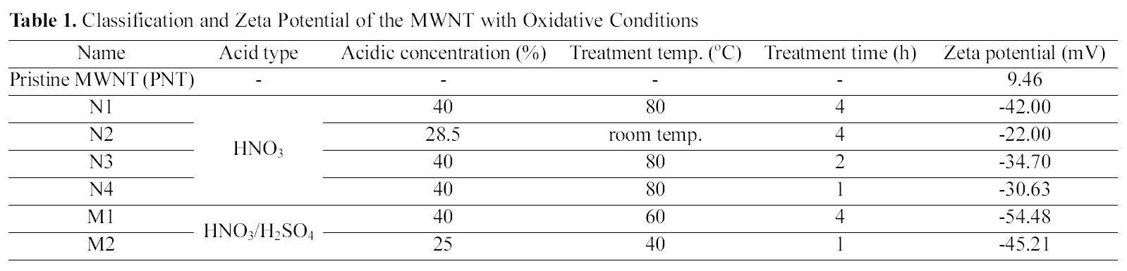
[Table 1.] Classification and Zeta Potential of the MWNT with Oxidative Conditions

Classification and Zeta Potential of the MWNT with Oxidative Conditions
analyzer and HRTEM. The DC conductivity of the PU composites as a function of the MWNT content are discussed in terms of the oxidation conditions and defects derived from oxidation process.
Commercially available thermoplastic PU (ESTANE®5708 TPU, Noveon Co., USA) was used as a matrix. MWNT (Hanhwa Nanotech Co., Korea) synthesized by a chemical vapor deposition with a carbon content of 95% were used as conductive fillers. In order to prevent entanglement of the MWNT and to obtain better dispersion, polyoxyethylene octylphenylether (Triton X100, Duksan Chemical Co., Korea) as a non-ionic surfactant, BKC (Junsei Chemical Co., Japan) as a cationic surfactant and calcium dodecyl benzene sulphonate (CS70, Cell Chemical Co., Korea) as a anionic surfactant are employed for all of the compositions, respectively. Methyl ethyl ketone (MEK) and 2-butoxyethanol (Butyl cellosolve, BC) as organic solvents are used.
2.2. Oxidation of MWNT and sample preparation
Oxidations of MWNT are dependent on acidic concentration, treatment temperature, and oxidation time. The MWNT oxidized under several treatment conditions are classified as shown in Table 1. All experimental details related with the liquid-phase oxidation were reported previously [10].
The various suspensions consisting of MWNT/BC (m/m =1/100), and surfactant were prepared with the kind of surfactants and their content to the as-prepared MWNT content, followed by ultrasonication at room temperature for 3 h to disperse the MWNT. The PU/MEK solution was poured into the dilute suspension of MWNT and the mixture was again mixed mechanically using homogenizer at 10,000 rpm for 10 min. Completely evaporating the solvent in the mixture in a vacuum oven at 60℃ for 4 h, the mixture was fully rollmilled at 70℃ for 20 min. The roll-milled mixture was
pressed at 100℃ for 15 min to obtain the specimens.
The oxidized MWNT classified with respect to oxidative
conditions and zeta potential values of all the MWNT are represented in Table 1. The zeta potential of the PNT exhibited positive values of about 9.5 mV, while the MWNT oxidized under six different conditions were negatively charged. As our previous report, the results imply that carboxylic groups are attached onto the surfaces of MWNT [10].
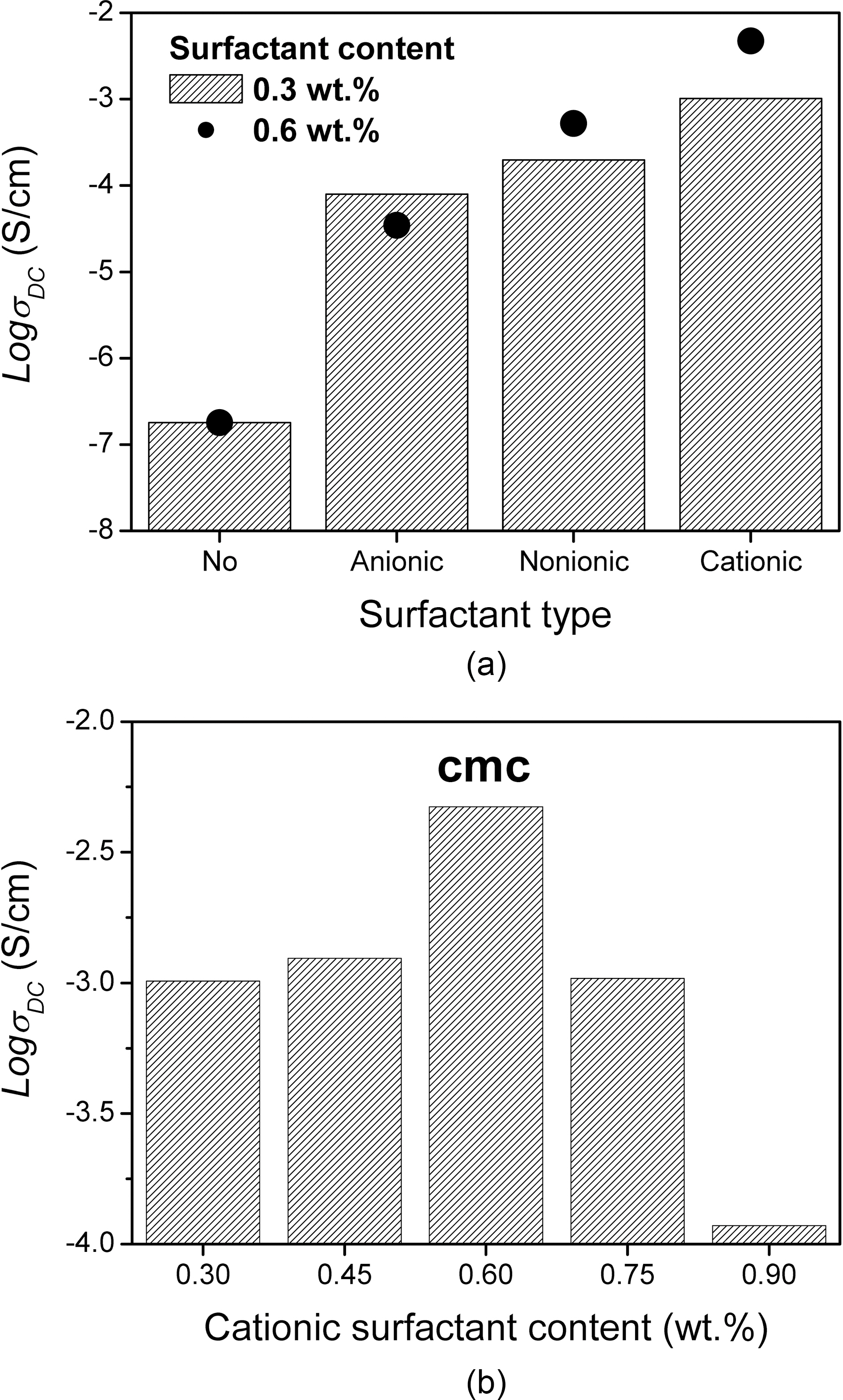
Fig. 1 (a) illustrates the DC conductivity by DEA (GmbH CONCEPT40, Novocontrol Co., Germany) of the PU composites filled with the oxidized MWNT (M2 in Table 1) of 1 vol. % with respect to the kinds of surfactant, and with and without surfactant. In contrast to
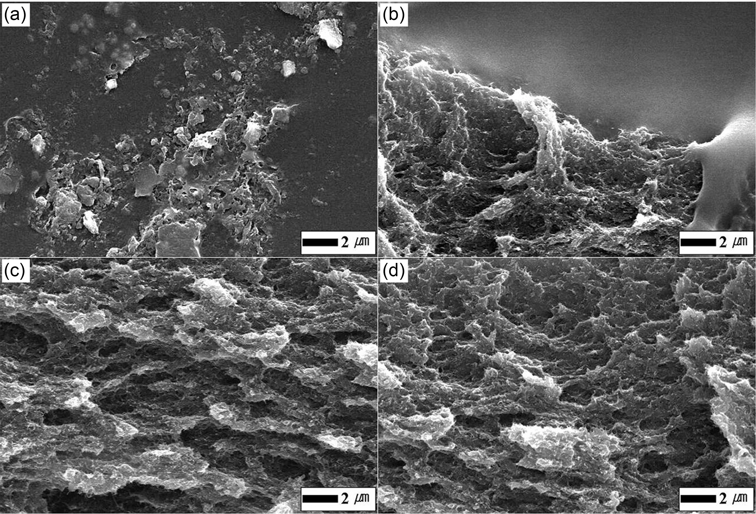
Fig. 2 shows FESEM (S-2700, Hitachi Co., Japan) images of the fractured surfaces in the M2/PU composites with the kinds of surfactant, also compares the dispersion of MWNT in PU matrix without and with surfactant. The three different types of surfactants 0.6 wt.% to the M2 were added to the PU composites with the M2 of 2 vol.%, respectively. As shown in Fig. 2(a), in the case of the M2/PU composite without surfactant, it is difficult to recognize individual MWNT due to very large M2 aggregates. The boundary between the M2 area and PU matrix are observed in Fig. 2(b), which is attributed to aggregates of residual anionic surfactants in the BC/M2 suspension and difficulty of their adsorption at the negatively charged M2. Very good dispersion of MWNT is found in both the composites filled with non-ionic surfactant and cationic surfactant, respectively (Fig. 2(c) and Fig. 2(d)). There are few the tangles and aggregates in the composites,and the M2 are homogeneously distributed because of the very effective oxidation of the M2 and better dispersion in MWNT suspension. Naturally the functionalities of the MWNT and adsorption of the surfactant can improve the dispersion and the interfacial adhesion, which result in electrical enhancement for the polymeric composites with MWNT.
Furthermore, for more electrical enhancement of the composites with the MWNT their intrinsic properties should be preserved with minimizing their damage induced from oxidation [10,12]. The typical HRTEM (JEM-4010, JEOL Co., Japan) images of pristine MWNT synthesized by low temperature CVD are shown in Fig. 3. They are very sinuous and highly tangled, and there exist many amorphous carbons (see the white arrow in Fig. 3(a)). Non-aligned “spaghetti like” shape, tangles due to electrostatic attraction and impurities prevent dispersion of the MWNT into individual ones. Low temperature CVD process may provide viable route to large-scale production of MWNT with high purity, while as-synthesized MWNT usually exhibit structural defects [13]. Likewise, partially discontinued and strippedoff side walls are found in Fig. 3(a) (see the black arrow).The MWNT in Fig. 3(b) grows asymmetrically and has internal cap like bamboo-like CNT (see the white arrow), at the circumference of which the walls are much wavier than other normal ones and the helix angle of graphite sheets is twisted (see the black arrow). At these regions, there may be a lot of non-hexagonal ring such as C5, C7 and Stone-Wales defect, and vacancies due to rotation of a bond in the CNT atom network or displacement of carbon atom. In contrast to chemically highly inert hexagonal structures, these defective sites provide the MWNT with chemical reactivity. Thus these defective sites may be more likely to be damaged by the chemical attack of acids, and the damage will propagate along the defective sites at the side walls as well as with the fullerene moieties at caps.
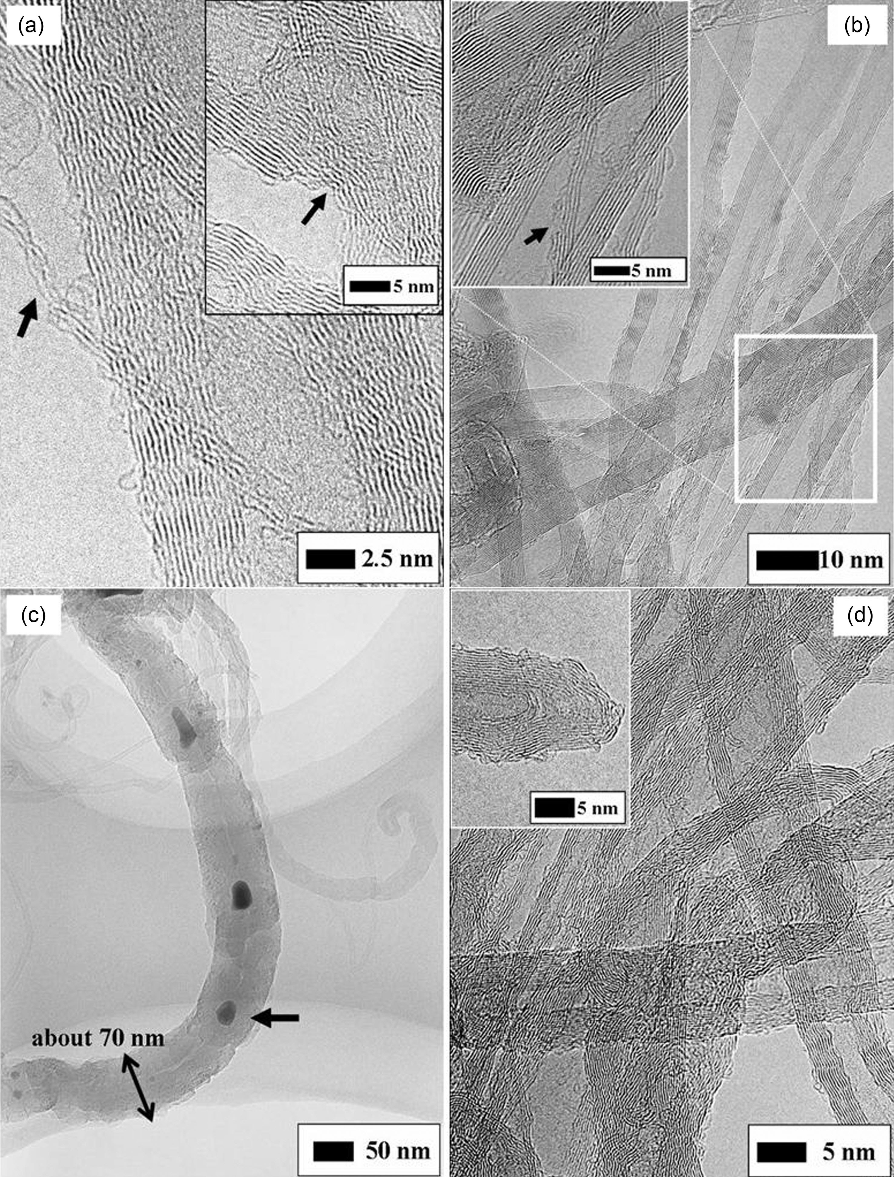
Fig. 4 shows HRTEM images of the MWNT oxidized under several conditions represented in Table 1. The N1 oxidized under a relatively higher acidic concentration, higher temperature and longer time compared with other Nseries MWNT were much destructed. The thinned MWNT and locally damaged MWNT are observed in Fig. 4(a) and its inset, respectively. Even if the outer walls lose their intrinsic electronic property, the non-damaged inner walls can undertake the charge transport to some extent. However, it is obvious that the intrinsic electronic properties of the damaged MWNT will be altered and in more details the workfunction required to quantum tunneling of an electron will increase. On the other hand, for both the case of N3 and M2 in Fig. 4(b) and (d), there are no defects and impurities with the exception that the MWNT is partially stripped-off (see the black arrow at inset of Fig. 4(b)). The condition of M2 may be so weak that incomplete cap opening are observed as seen at inset of Fig. 4(d). The N3 and M2 keep the intrinsic wall shape without extraordinary damage. The MWNT is completely ruptured and Co particles are trapped as indicated the black arrow in Fig. 4(c). Due to the destruction of crystalline structure, it is swelled up to about 70 nm in diameter and its hollow tube disappears. G. Wei et al. already reported that oxidation by 0.5 mol/l sulfuric acid leaded to the rupture of the MWNT synthesized by low temperature CVD [14]. Since the surface density of preexisting defect depends on the synthesis method of CNT, the degree and type of damage can be varied even at same oxidation condition.
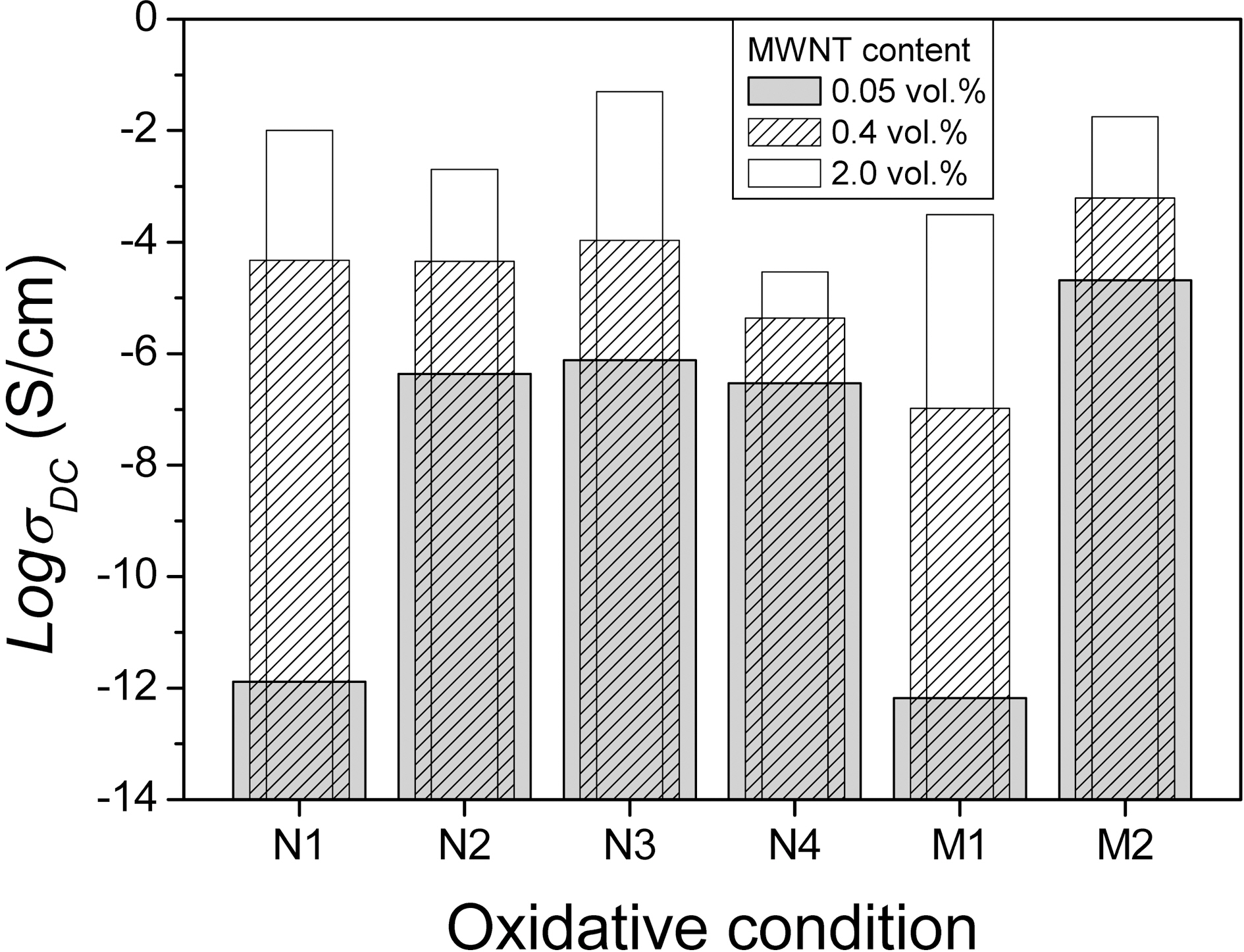
Fig. 5 shows the DC conductivity as a function of the MWNT content of the PU composites with respect to the
oxidation conditions. The benzalkonium chloride was employed in all compositions at a concentration of 0.6 wt.%to each oxidized MWNT. We previously reported that the percolation threshold of each epoxy composite occurred at a different MWNT content depending on the oxidization conditions, and an explicit trend in which the stronger the oxidation conditions the higher the percolation threshold of the composite was observed regardless of the solution used [10]. In the same manner, especially in very low 0.05 vol.% of MWNT content,
relative high content the dispersion degree of MWNT plays a central role in electrical property of the composites because the electrical conductivity of the composites with MWNT increase as a function of adjacent distance between MWNT or clusters. No matter how high the zeta potential of M1, the M1/PU composite still shows lower DC conductivity for other composites. It is why as shown in Fig. 4(c) the sever damage of MWNT such as rupture decrease its conductance, which causes the DC conductivity of the resulting composite to be reduced. At loading level of 2 vol.%, the N4 composite shows the lowest DC conductivity among the different oxidized MWNT composites. This may be why the adjacent distances between the N4 or N4 clusters can be not decreased in spite of the increment of N4 content due to lower zeta potential and functionalities compared with other oxidized MWNT. It can be seen that although the PU composites contain the same amount of MWNT, the resultant conductivity of the composites is sensitively influenced by the oxidative conditions of the MWNT. The N3 and M2 were found to represent the optimal state of oxidation from the viewpoint of the electrical conductivity of the polymer composite.
The surfactant embedded into composites showed much better dispersion of the MWNT and higher electrical conductivity regardless of the kind of surfactants compared to those of the composites without surfactant, in particular, the composites with benzalkonium chloride of 0.6 wt.% to the oxidized MWNT was the best. The damage of MWNT by a liquid-phase oxidation is inevitable, and this process causes various types of defects such as cap opening, thinning, and rupture due to the chemical reaction of defective sites and acidic solutions. The MWNT/PU composites show different DC conductivity behavior in terms of the degree of damage in spite of the same process and the same MWNT content. The N3 and M2 conditions are the most effective from the viewpoint of dispersion and damage of MWNT, which leads to the most electrical enhancements of the composites at whole measurement ranges of MWNT content.