Silicate layer minerals represent the largest volume of filler second to carbon black in the rubber industry. The silicate mineral used is primarily Kaolin clay. Kaolin occurs naturally. Kaolin clays are mined and they are subsequently pulverized and refined by air and water separation process to remove impurities (mainly quartz and mica). Both ‘soft’ and ‘hard’ clays are obtained. The classification is based on the rubber compounds produced. Hard clays possess small particles (<2 ㎛) and soft clays contain large particles. The name ‘clay’ itself implies that particles of the material are very fine [1].
Clay minerals are classified into kaolinite, illite, smectite (montmorillonite), etc. The most important commercial clay minerals are kaolinite and montmorillonite. Kaolin or kaolinite, known as ‘China clay’, has the basic chemical formula Si2Al2O5 (OH)4 and montmorillonite is AlSi2O5(OH)· xH2O. Kaolinite was formed by various hydrothermal alterations or weathering of feldspars, and other silicate minerals.
Comparing structure of kaolin and montmorillonite, kaolin has 1:1 layer lattice and montmorillonite has 2:1 lattice structure. Kaolin consists of successive layers of alumina and silica mineral (silica-alumina) whereas montmorillonite has two layers of silica with a layer of alumina sandwiched between them (silica-alumina-silica)
Calcining of kaolin at 1,100℃ leads to considerable shrinkage and causes some of the ‘books’ to open (split of the plate layers), but the finer particles fuse with the larger to yield a generally lower surface area.
As a secondary processing after the water suspension, a delamination process cleaves or splits the kaolin into very thin platelets. Delamination can be achieved by abrasion using beads as the grinding medium or extrusion of a kaolin water paste [2]. Aspect ratios for delaminated grades are as great as 200 to 1 for large platelets [3].
Kaolin has long been recognized as safe for use in compounds contacting food, because of its naturally low concentrations of toxic elements. Calcined kaolin is the most widely used filler for insulation to provide superior properties under humid or wet conditions and their property increases with treatment of the surface to hydrophobic. Kaolin has replaced asbestos in phenolic molding compounds for break shoes and pads, where it gives dimensional stability,reinforcement, and low abrasiveness. Due to its fine particle size and pastiness, it improves surface smoothness and reduces warping, cracking, and crazing. Delaminated grades especially provide increased flexural modulus.
Calcined kaolin is primarily used in the rubber industry as a filler. It is being widely used in innerliner compound in tubeless tire industry. Use of kaolin in glass fiber reinforced thermosets improves surface quality, reduced warpage, and lower crack formation. Surface treated calcined kaolines are used for tire wheel cap made from polyamides and greenhouse films from low density polyethylene [4].
In Part I and in Part II, we have shown the various silane effects on hard clay (Suprex) and soft clay (GK990) filled carbon black/chlorobutyl rubber (CIIR) compounds, respectively. The vulcanization properties, the processability, and the physical properties of the compounds are investigated.
In this part, we compare hard clay (Suprex) and soft clay (GK990) filled carbon black/CIIR compounds at the same condition as shown in Part I and Part II. The rheological properties and mechanical properties are measured and both compounds are compared how they are affected by the addition of various silanes. We also compare a new silane additive ZS with other additives whether they effect the processability and the mechanical properties of the compounds.
[Table 1.] Materials Used in This Study
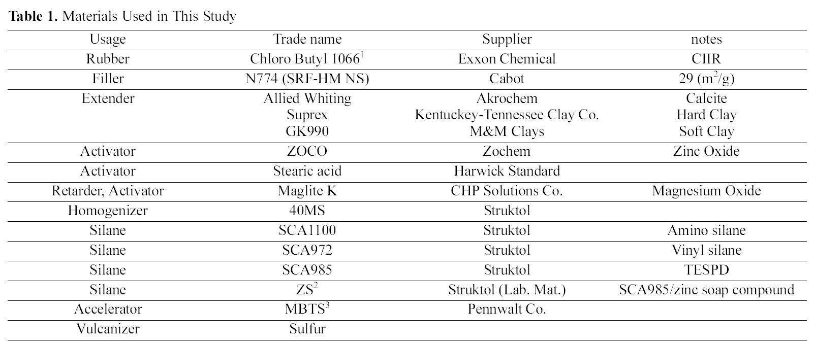
Materials Used in This Study
[Table 2.] Mixing Formulations and Procedure for CIIR Compounds
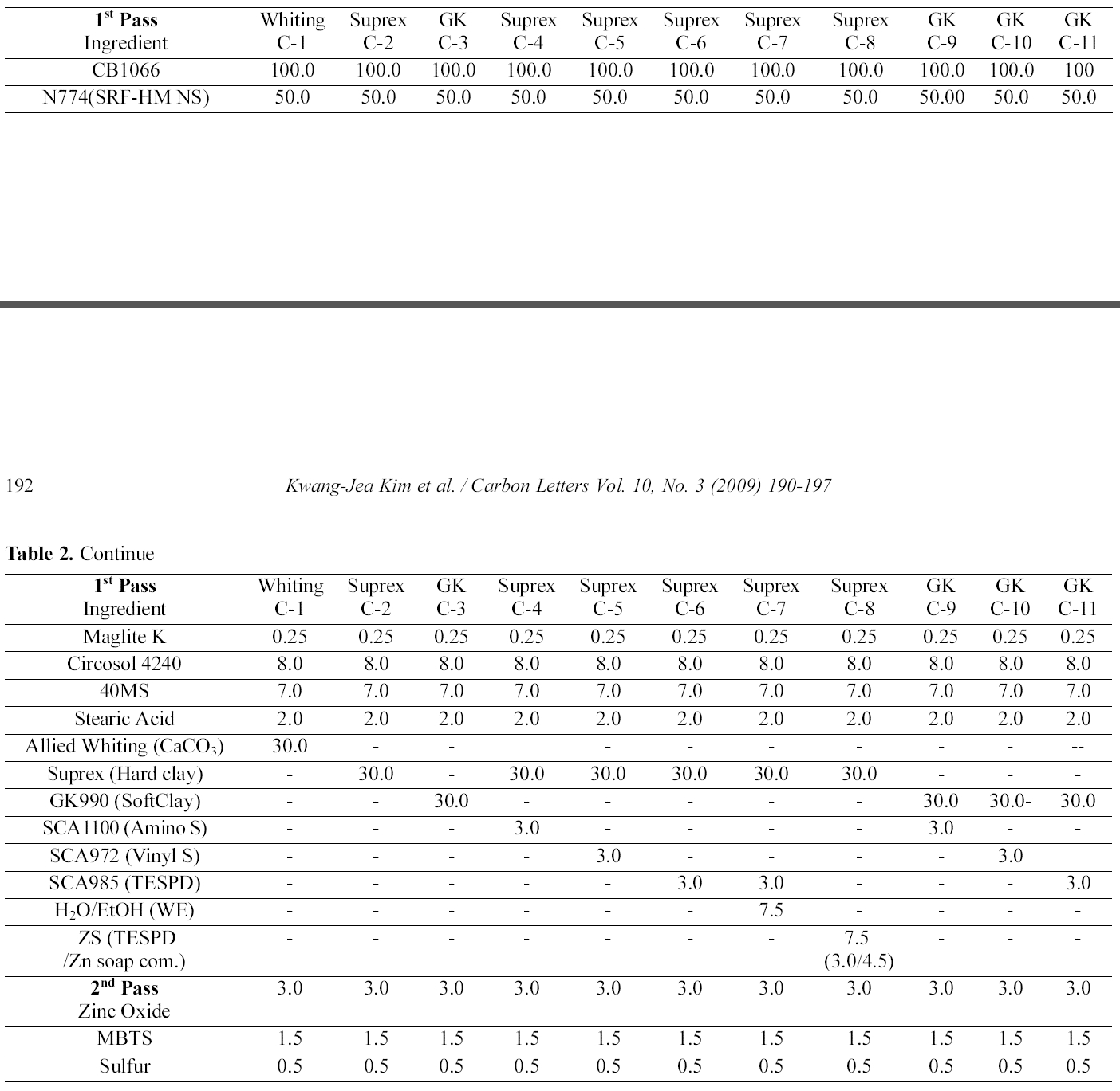
Mixing Formulations and Procedure for CIIR Compounds
Various silanes were used in this study including amino silane (SCA-1100), vinyl silane (SCA-972), and sulfur containing bifunctional organo silane (SCA985 bis (triethoxysilylpropyl) disulfide (TESPD) (S2). And ZS (TESPD/zinc soap complex) was prepared in our laboratory. Structures of silanes used are shown in Part I. Chlorobutylene-isoprene rubber (CIIR) was supplied by an Exxon Chemical the brand name of CB1066. The carbon black (CB) used was N774 (SRF-HM NS), which has BET 29(m2/g) product of Cabot. Various additives, including activators (ZnO, stearic acid), Maglite K (magnesium oxide, scorch retarder, activator, vulcanizer, acid acceptor, stabilizer, UV screener), processing aid, plasticizer, dispersing aid, (Circosol 4240), homogenizer (40MS, aromatic and aliphatic hydrocarbon chain mixture), extender (Suprex (hydrous aluminum silicate, hard clay), median particle diameter 0.3 ㎛, BET 22~26(m2/g), GK990 (hydrous aluminum silicate, soft clay), median particle diameter 1.3 ㎛, BET 17(m2/g)), Allied whiting (calcium carbonate, mean particle size 15.5 ㎛), curing agent (Sulfur), and accelerator (MBTS (2,2’-dithiobisbenzothiazole)), were used. The information on the materials used in the study is summarized in Table 1.
2.2. Processing and Characterization
In order to compare hard clay and soft clay filled system, we measure at the same condition as shown in Part I and Part II. The mixing formulations and procedures are summarized in Table 2.
2.2.2. Mixing Procedure
1st stage mixing (Master batch mixing (MB1)): Fill factor 0.8, 60 rpm and 30 psi
Starting Mixer Temp: 70℃ (158℉)
1. Add rubber
2. Mix for 90 sec
3. Add CB and other additives
4. Mix for 150 sec and sweep.
5. Sweep at 210 sec
6. Drop at 300 sec (or 140℃/284℉)
2nd stage mixing (MB2): 60 rpm and 30 psi
Starting Mixer Temp: 65℃ (150℉)
1. Add MB1 and curatives
2. Drop at 120 sec (or 100℃ (212℉)).
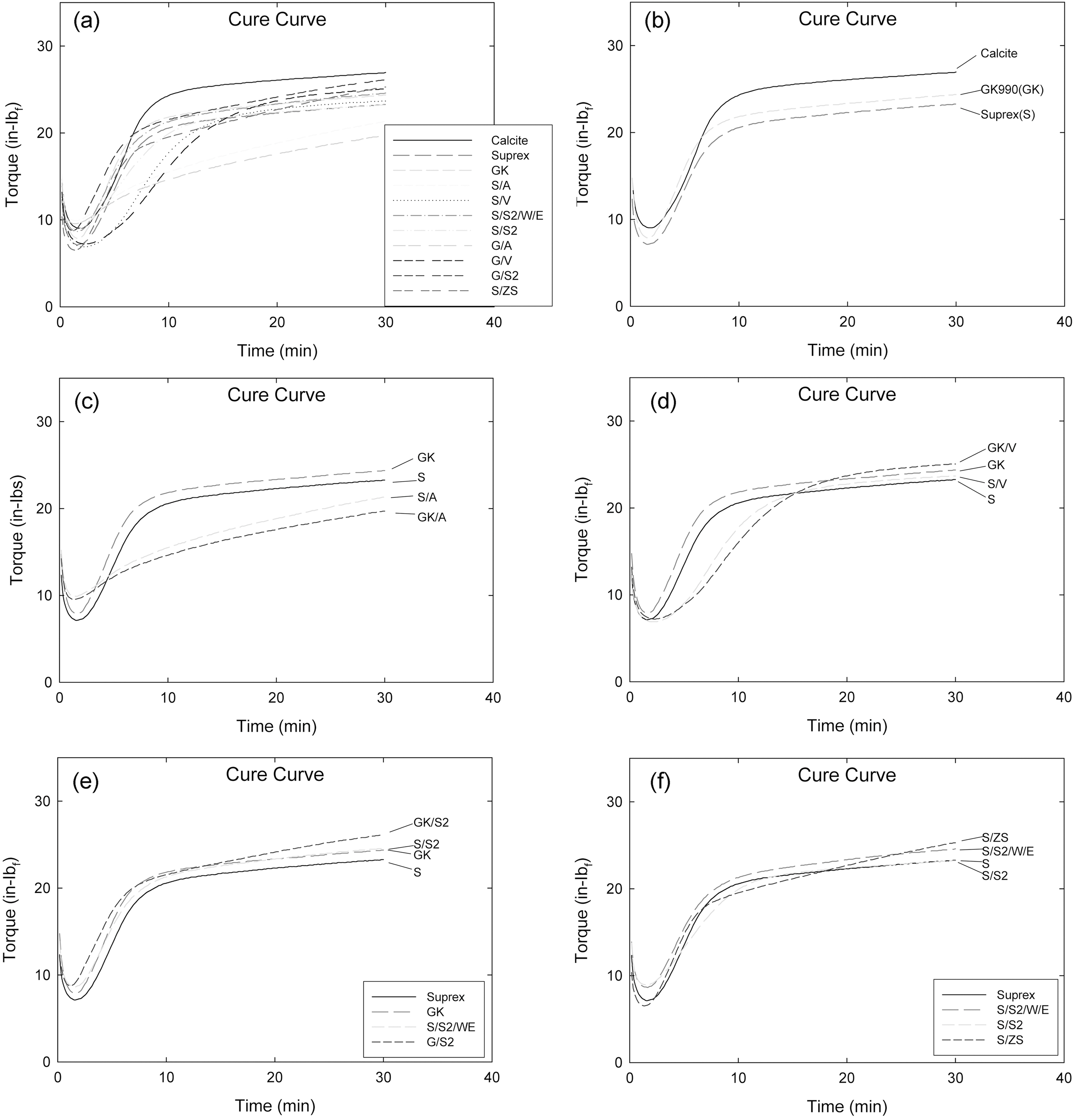
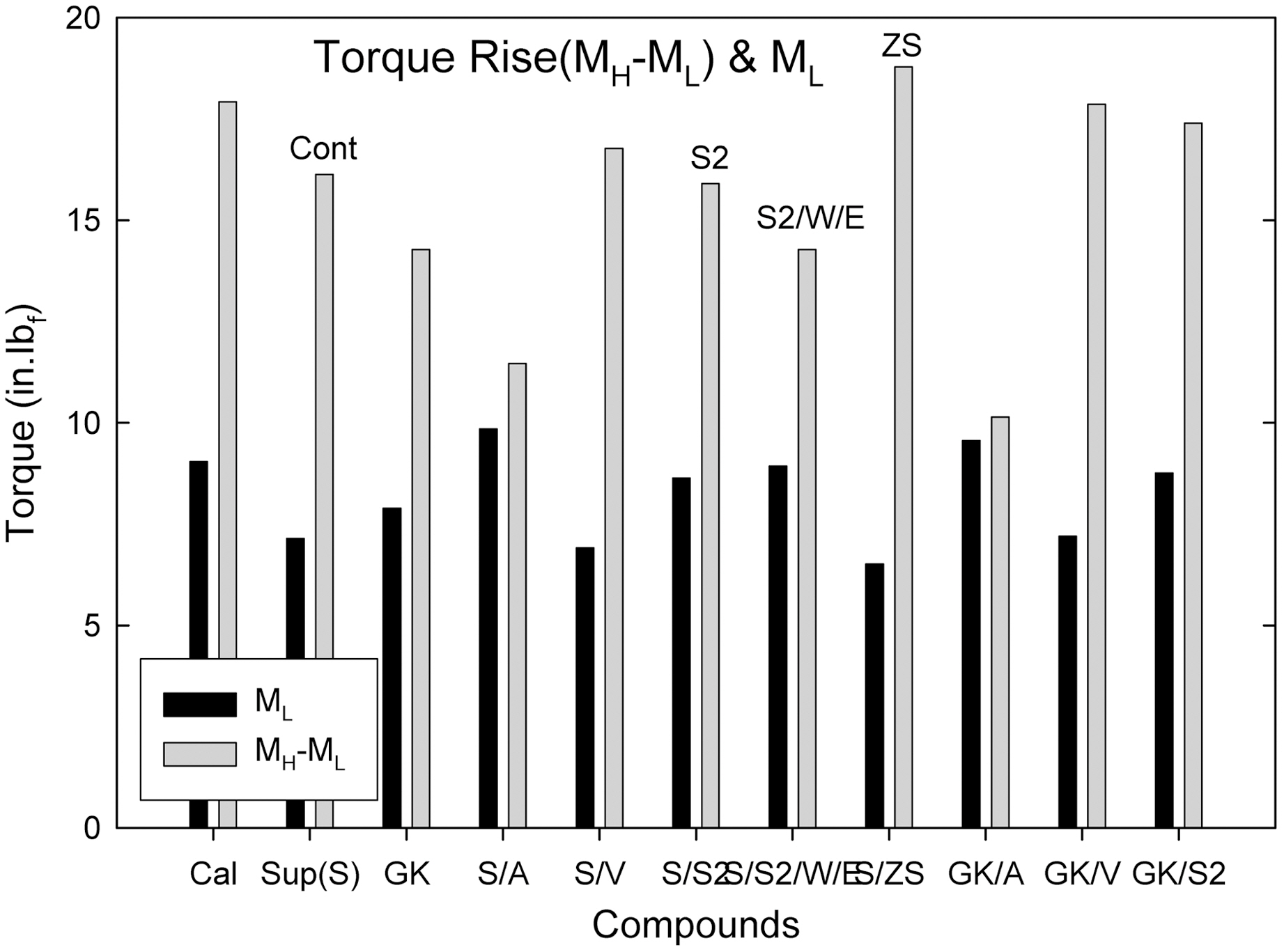
Generally, higher torque compound shows a higher degree of crosslinking with higher mechanical properties when they show a plateau torque during curing.
Fig. 1(b) shows a comparison of cure curves of Calcite, GK and Suprex particle filled systems. GK filled compound showed the highest torque curve then Suprex filled one.
Fig. 1(c) shows a comparison of amino silane treated-GK and -Suprex particle filled compound. Both the amino silane treated compounds (S/A, GK/A) showed a steady marching behavior and delayed cure behavior compared to the Control compounds (S, GK), respectively. The S/A filled compound showed a higher torque curve then the GK/A one.
Fig. 1(d) shows a comparison of vinyl silane treated-GK and -Suprex particle filled systems. Vinyl silane treated compounds (S/V, GK/V) showed a delayed cure behavior compared to Control compounds (S, GK), respectively. The S/V filled compound showed a lower curve then the GK/V one.
Fig. 1(e) shows a comparison of S2(TESPD) silane treated-GK and -Suprex particle filled compounds. The S2 silane treated compounds showed a slightly accelerated cure behavior compared to the Control compounds. The S/S2 filled compound showed lower curve then the GK/S2 one.
Fig. 1(f) shows a comparison of S2 (TESPD) and ZS silane treated Suprex particle filled compounds (S, S/S2, S/S2/W/E, and ZS). The S2 silane treated compounds showed equal or higher cure curves than the S compound. Among them the ZS treated compound (S/ZS) showed the highest curve and showing marching behavior.
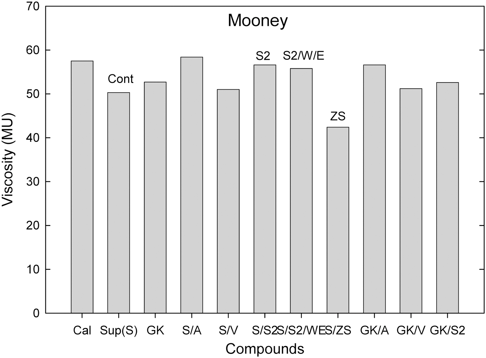
Among them (Suprex and GK with and without additives), the S/ZS compound showed the lowest viscosity.
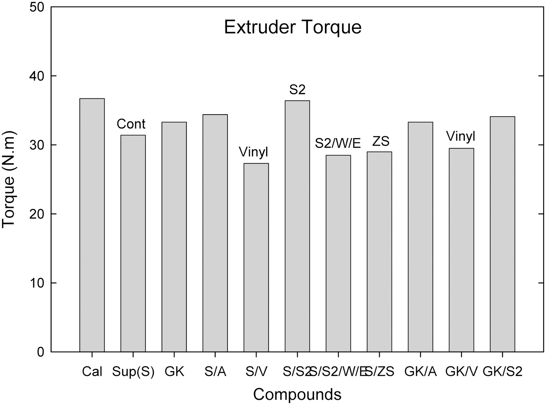
Among them (Suprex and GK with and without additives),
the S/ZS, S/V, S2/WE compounds showed a group of the lowest torque.
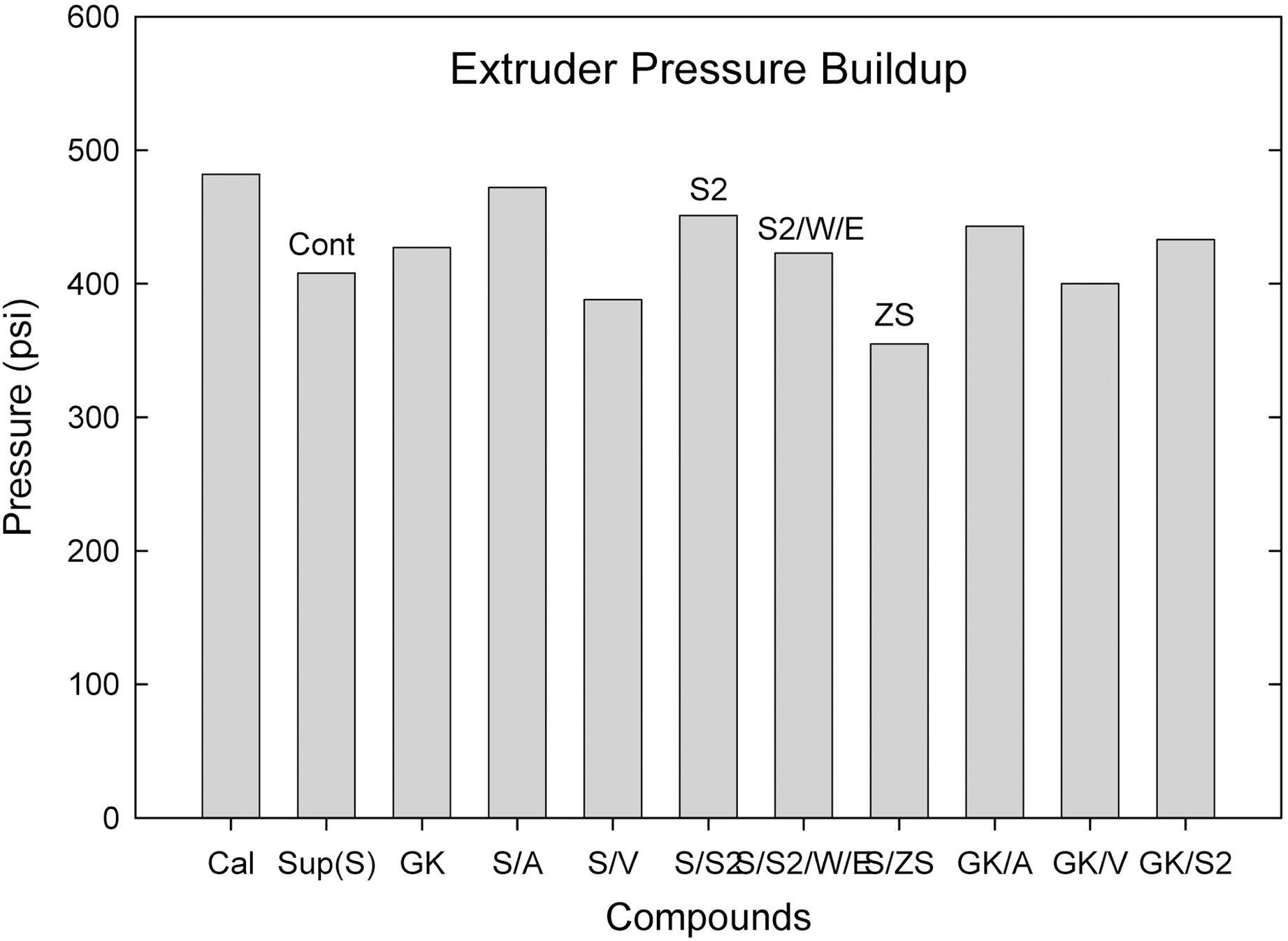
Among them (Suprex and GK with and without additives), the S/ZS compound showed the lowest extruder pressure buildup following S/V compound.
Among them (Suprex and GK with and without additives),
the S/ZS compound showed the highest viscosity.
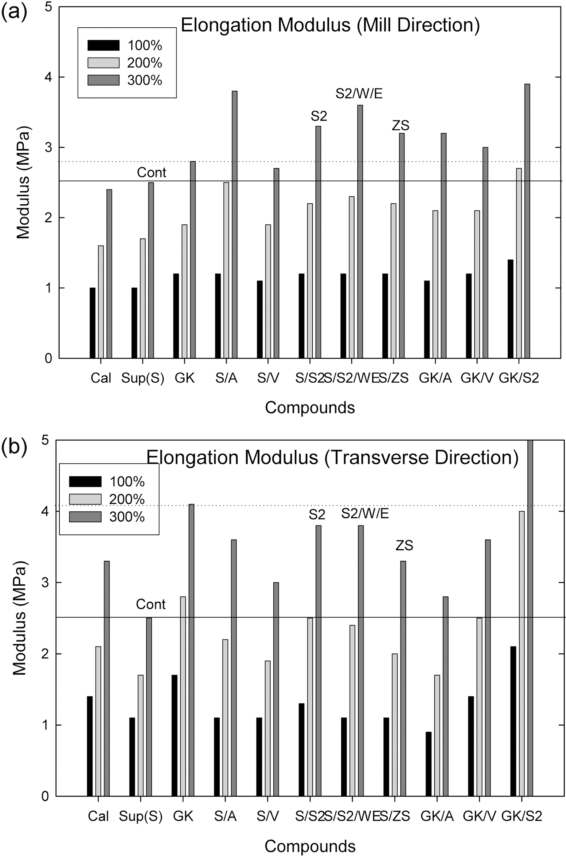
Depending on mill direction between parallel to milling direction(MD) and transverse direction (TD), compounds Cal., GK, S/V, S/
S2, GK/V and GK/S2 showed a significant change in modulus
Among them (Suprex and GK with and without additives), the S/V, S/S2, GK/V, and S/ZS compounds showed a higher modulus than the Control.
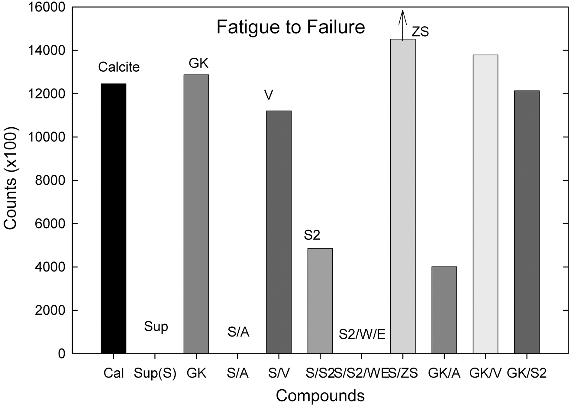
The S, S/A, and S/S2/W/E compounds showed a creep behavior of the specimen resulted in no fatigue to failure
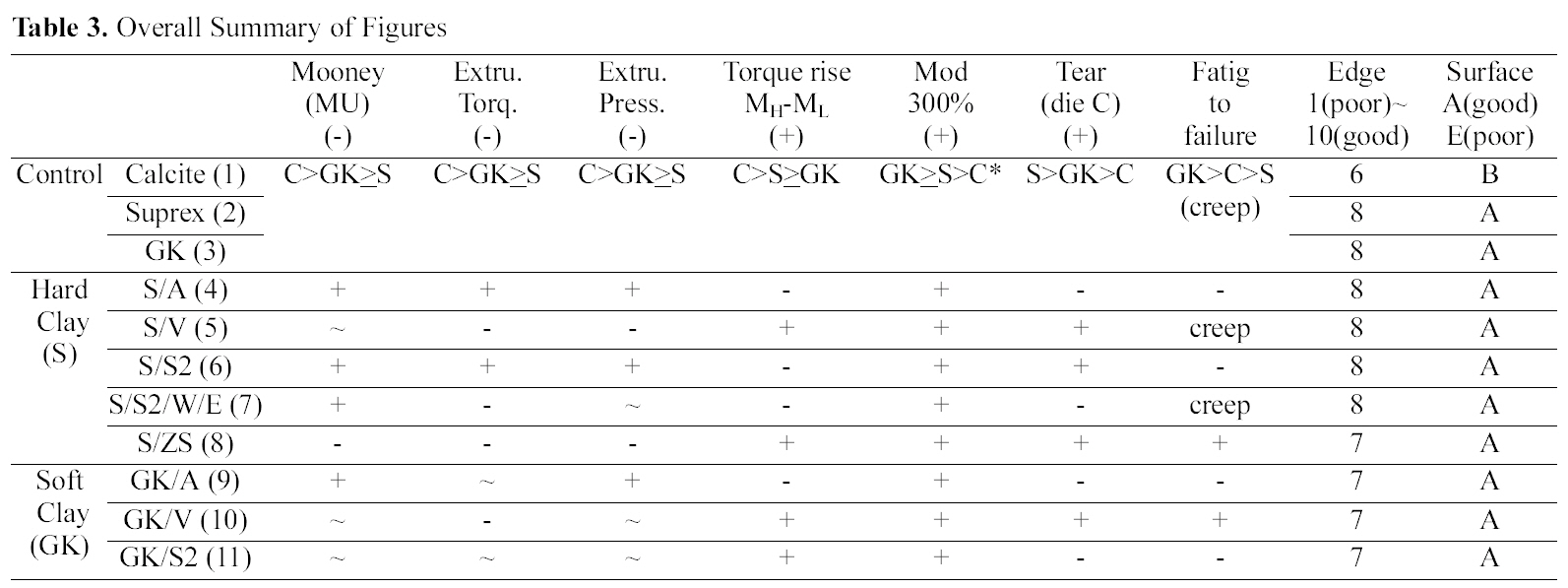
[Table 3.] Overall Summary of Figures

Overall Summary of Figures
counts (average). The ZS added S (Control) compound showed a significant improvement on fatigue to failure counts. It showed significantly higher counts than the GK (Control) compound. Half of the ZS added compounds (3/6) were still did not fail up to 1,500,000 counts thus we had to stop the machine for the next experiment.
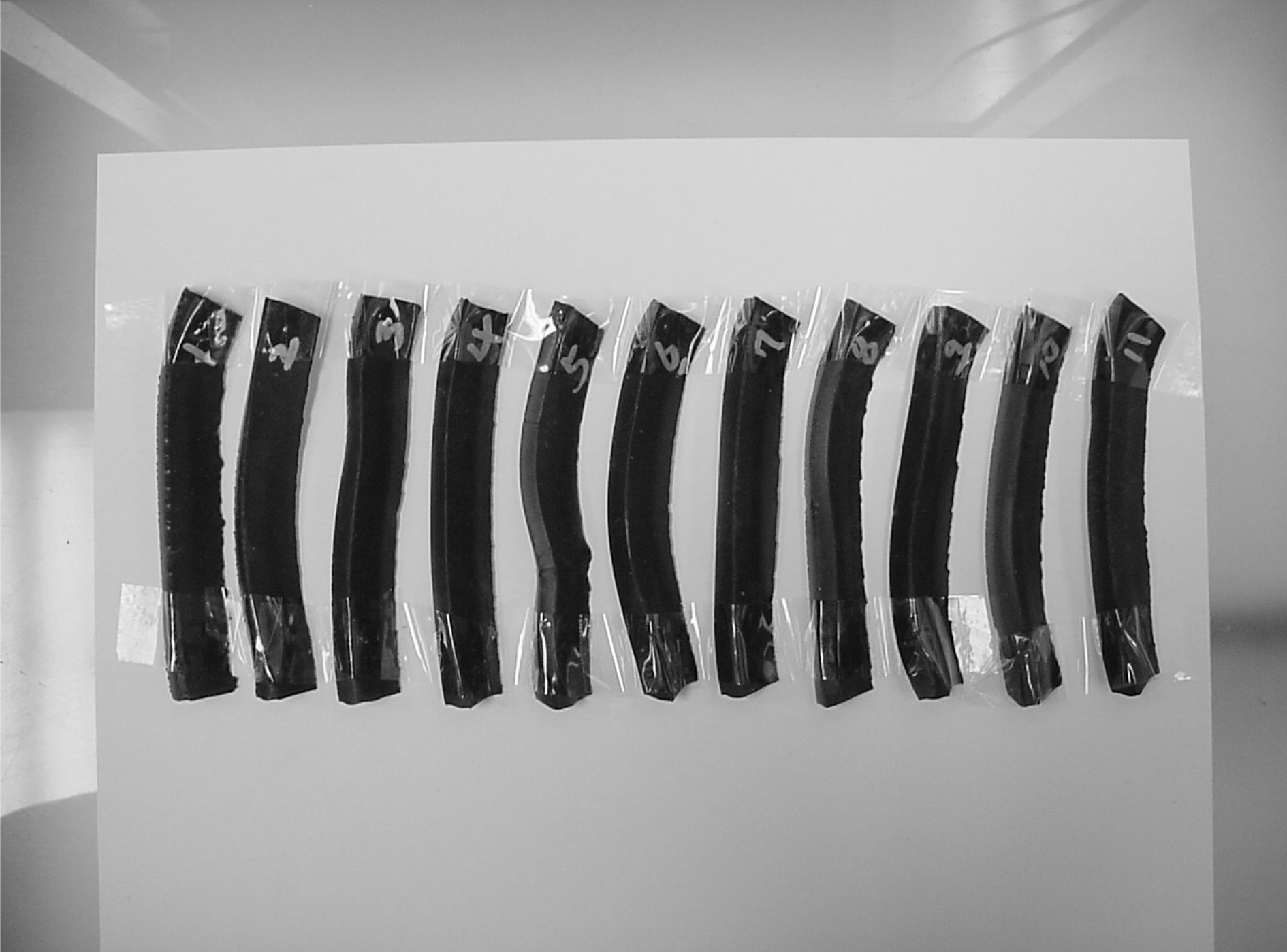
Fig. 9 shows a extrudate surface of each compound extruded from Brabender single screw extruder. There were no significant differences in edge and surface smoothness among compounds.
Authors have shown the effects of various silanes on hard clay [5] and soft clay [6].
Comparing calcite, hard clay and soft clay compounds without surfactants, calcite filled one showed a higher Mooney viscosity, extrusion torque, extrusion pressure build
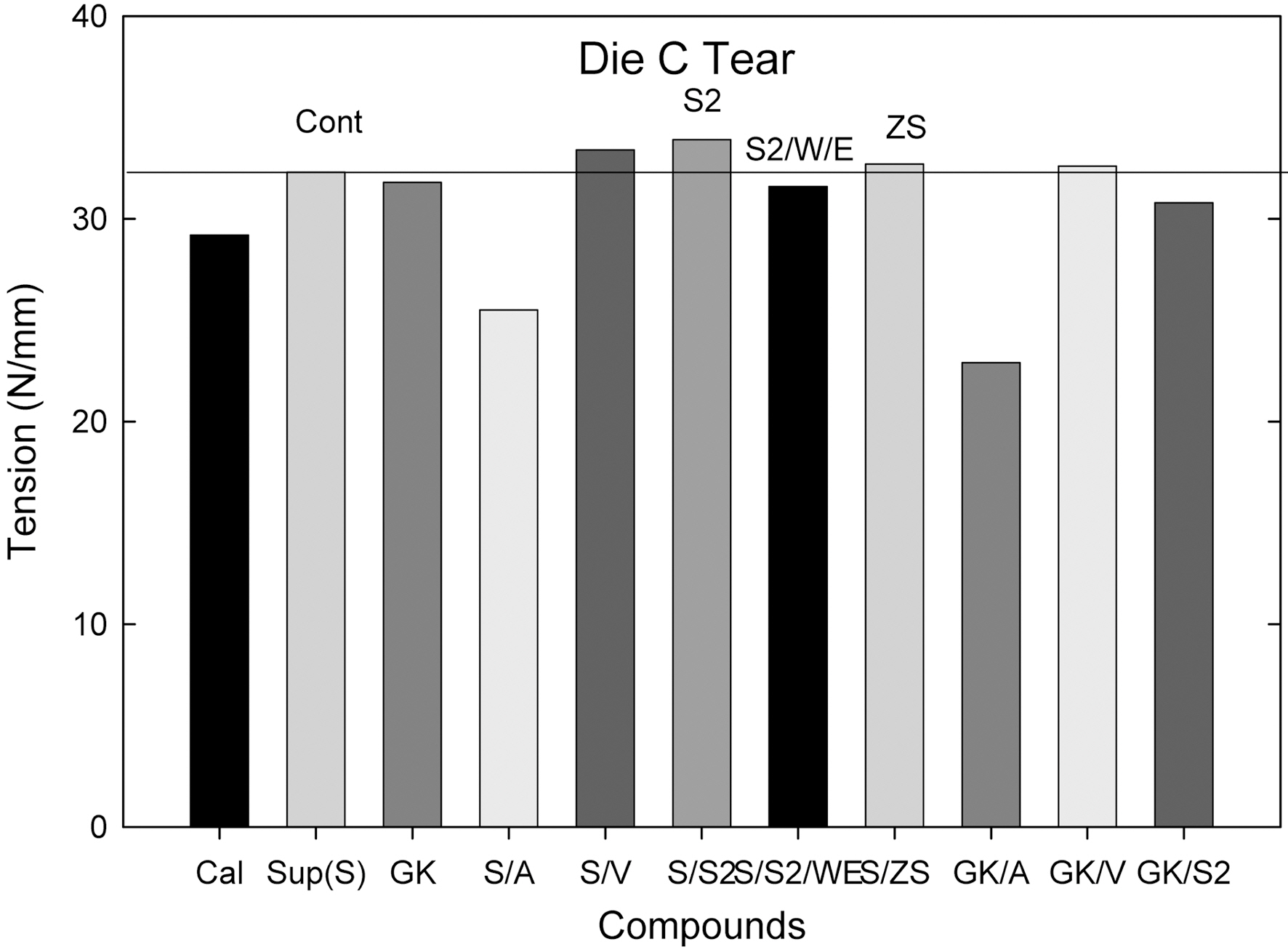
up, torque rise than the hard and soft clay filled ones and there were no significant differences between hard and soft clay filled compounds. In die C tear experiment, hard clay filled compounds showed a higher tear resistance than the soft clay filled one; however showed a lower fatigue to failure property.
Comparing silane (amino, vinyl, and S2) added compounds, extrusion torques was increased by the addition of sulfur silane while other silane added ones did not show significant differences on both hard and soft clay filled ones. Elongation modulus properties were increased by the addition of silanes. The vinyl silane added compounds showed reduced extruder torque and increased mechanical properties in both hard and soft clay filled compounds.
Overall only the ZS and vinly silane added compounds showed both improvements in processability and mechanical properties as shown in Table 3.
The particle size of hard clay (Suprex) used is 0.3 mm and that of soft clay (GK990) is 1.3 mm. In processability test, comparing Control compounds (S vs. GK), the addition of various silanes did not show a significant changes in processability, which implicated that the particle size effect was not significant. However in edge test, hard clay filled compounds showed a better edge surface than the soft clay filled ones. This is clearly due to small particle size of the hard clay. Amino silane added compounds showed a marching behavior and their MH values were lower than that of the Control compounds as shown in Fig. 1(c). This is directly related with low mechanical properties of their compounds as shown in Table 3. In die C tear test, hard clay filled Control compound showed an improvement of tear
strength when vinyl silane and S2 were added, while in soft clay filled one, it was increased when vinyl silane was added. It is clear now that vinyl silane works well on both clays. However, S2 works only on hard clay filled one. This may be related with particle size of clays. The hard clay has a large surface area than the soft clay, which gives a higher probability to chemically react with the S2. In zinc surfactant added compounds, the compound showed both improved processabilities, and increased mechanical properties. It seems that the ZS effectively helped a formation of a strong 3-dimensional network structure between silicate surface and CIIR via expansion and contraction mechanism of zinc ion.
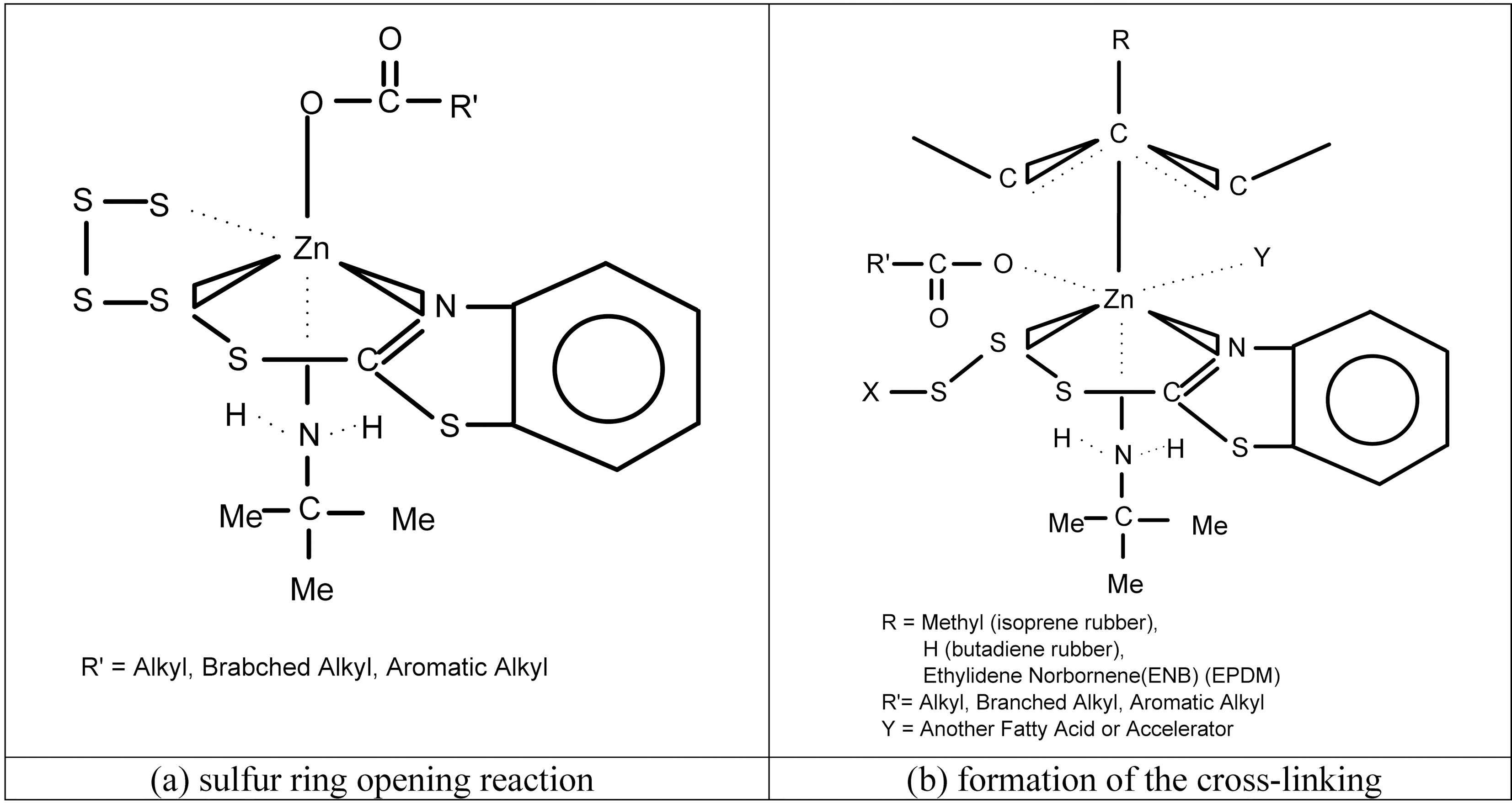
We revisited the role of zinc ion for sulfur-double bond coupling mechanism [7]. Zinc, as a transient element, is known to form complexes with accelerators [8]. The complexes are typically 4, 5, or 6 coordinated. There is also evidence thatπ-π allyl complexes of zinc form between zinc and simple olefins [9]. The ligand complexes, a series of 4, 5, and 6 coordinated zinc structure explains the vulcanization process of all the coordinate sites on zinc and the electron nature of the carboxylate using expansion and contraction of the zinc orbitals [7]. The cross-linking mechanism with rubber matrix was explained by sulfur ring opening mechanism via bipyramidal model [7]. Two examples shown are for the sulfur ring opening reaction as shown in Fig. 10 (a) and the formation of the cross-linking as shown in Fig. 10 (b). The sulfur ring opening reaction is shown as a bipyramidal complex with sulfur and oxygen anions, and sulfur and two amino ligands (residue from accelerators). The crosslinking intermediate allows for the transfer of sulfur from the polysulfide accelerator to the rubber in a concerted mechanism. The π allylic model can be used to explain the carbon sulfur formation and types that form during vulcanization [7].
Comparing the Control compounds as shown in Table 1, hard clay (Suprex) filled system showed a higher die C tear than the soft clay (GK) filled one. The other properties (Mooney, extrusion torque/pressure, torque rise (MH-ML), modulus at 300%) were close to each other.
When additives, silanes (amino-, vinyl-, TESPD, ZS) and H2O/EtOH, were added, the ZS treated hard clay (Suprex) compound showed the highest mechanical property following S/V and GK/V compounds (ZS >Suprex/Vinyl>GK/Vinyl).
Overall, The ZS added compound showed both improved processability (Mooney, Extrusion torque-& pressure) and improved mechanical properties (degree of crosslinking, elongation modulus, tear, and fatigue to failure counts).


![(a) Sulfur ring opening reaction and (b) the formation of the cross-linking [7].](http://oak.go.kr/repository/journal/10455/HGTSB6_2009_v10n3_190_f010.jpg)