Electrocatalytic oxidation of methanol is of great importance in the electrochemistry of direct methanol fuel cells (DMFCs) for their potential as clean power sources [1-5]. Metallic nanoparticles are attracting attention due to their potential applications in catalysis and electric materials. To increase the electrochemical activity of methanol oxidation, an enormous effort had been devoted towards the development of catalysts. These catalysts include supported or unsupported metallic nanoparticles such as Pt, Ru, Pd, Ni, and others. The main requirement of a good electrode is a formation of three-phase boundary among the supply of fuel reactants, catalyst particle, and a protonic conductor. In commercializing fuel cells, one of the most critical problems is the cost of metal catalysts deposited on electrodes. Fine metal particles are dispersed on large-specific-surface-area carbon supports to reduce the total metal amount and to enhance the catalytic activity.
Catalysts can be prepared by an electrochemical plating method as well as a conventional chemical-reduction method [6-8]. Recently, electrochemical deposition of metal catalysts has been receiving more and more attention due to advantages such as the high purity of deposits, the simple deposition process, and the easy control of the loading mass. The size and dispersion of catalyst particles on the substrate determine the catalysts’performance as an electrode material. T.H. Lee et al. proposed that Pt nanoparticles as catalysts for proton exchange membrane fuel cells be prepared by pulse electrodeposition [8]. However, potential cycling methods had not fully been studied and the precise preparation condition for obtaining the superior catalysts was not investigated thoroughly to our best knowledge.
Besides, the development of a support material is essential to minimizing noble metal loading and achieving optimum catalytic performance [9-14]. Carbon materials have generally been used to support nano-sized Pt and Pt-based particles for the electro-catalytic oxidation of methanol in DMFCs. Carbon blacks commonly used as a support material, exhibit microscopic and turbostatic-structured carbon grains of 30~70 nm size. Novel types of carbon materials are also applied to bio-related or energy-related devices [15-17]. In our study, CNTs were selected as the support materials for catalyst deposition in order to obtain an available surface area, better catalyst dispersion, and the resulting high electroactivity. The aim of this study was to overcome the problem of the complexity of catalyst preparation by using a simple electrodeposition. Furthermore, potential cycling methods were performed to study the effect of electrical condition for deposition on the catalytic activity.
2.1. Electrodeposition of Pt nanoparticles on support
Electrodeposition of Pt nanoparticles on carbon support was performed using an Autolab with a PGSTAT 30 electrochemical analysis instrument (Eco Chemie B.V.; Netherlands). The solid precursors of chloroplatinic acid (H2PtCl4, Aldrich) were used without purification. A standard three-electrode cell was employed. Carbon nanotubes (CNTs) were selected as the support material. The CNTs, supplied from Hanwha Nanotech, Korea (Multiwalled nanotubes, Product name: CM-95, Purity: >95 wt.%), were used without further purification. The CNTs were synthesized by a chemical vapor deposition (CVD) process.
The CNTs mixed with 10% Nafion®, perfluorosulfonated ion-exchange resin (Aldrich) solution, were dropped onto a glassy carbon electrode, selected as the working electrode. A Pt wire as the counter electrode and KCl-saturated Ag/AgCl as the reference electrode were used, respectively. Pt nanoparticles were electrodeposited on the CNTs/ Nafion®- composite electrodes by multiple potential cycling. An electrolyte solution was a distilled water solution containing chloroplatinic acid. In the chloroplatinic acid dissolved solution, the atomic concentration of Pt was 20 mM. A potential function generator was used to control the potential cycling and cycling time. For potential cycling method, the potential was cycled in the range of 0.3 V to 0.8 V with 20 mV/s scan rate. The catalysts were prepared by changing the plating time from 4 to 8, 12, and 16 min.
An XRD analysis was carried out on the catalysts by means of a Rigaku D/MAX- III B X-Ray diffractometer, using a Cu Kα source operating at 45 kV and 100 mA. The XRD patterns were plotted at a scanning rate of 4 deg/min-1 with an angular resolution of 0.05° for 2
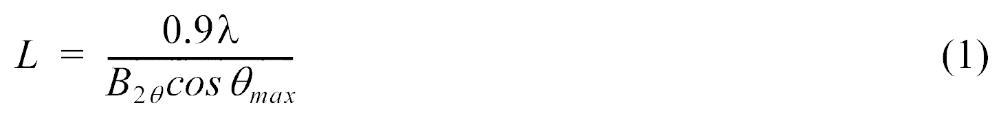
where λ is the X-ray wavelength (1.54056A for the CuKα radiation), B2
Transmission electron microscopy (TEM) of the catalyst samples were taken using a transmission electron microscope (JEOL, JEM-2010F), with a spatial resolution of 1 nm. Before taking the electron micrographs, the catalyst samples were finely ground and ultrasonically dispersed in isopropyl alcohol, and a drop of the resultant dispersion was deposited and dried on a standard copper-grid coated with a polymer film. The applied voltage was 100 kV for the catalyst.
2.3. Electrochemical measurements
Electrochemical measurements were carried out in a conventional three-electrode electrochemical cell at 25℃. A piece of Pt wire was used as a counter electrode, and KCl-saturated Ag/AgCl was used as a reference electrode. The above electrically deposited catalyst electrodes were used as working electrodes. All of the solutions were prepared with ultra-pure water. A solution of 1M CH3OH and 0.5M H2SO4 was stirred constantly and purged with ultra-pure argon gas before the measurements. Electrochemical experiments were performed using an Autolab with a PGSTAT 30 electrochemical analysis instrument (Eco Chemie B.V.; Netherlands). The potential was cycled in the range of 0.3 V to 1.1 V with 20 mV/s scan rate.
3.1. Crystalline Size and loading level of catalysts
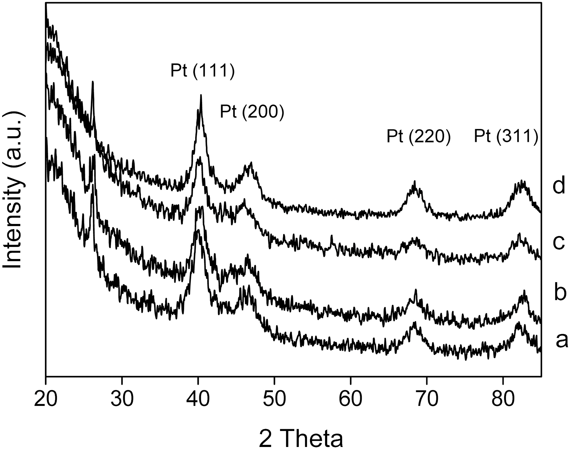
The crystalline structures of the Pt/CNTs catalysts and crystalline size of Pt nanoparticles were investigated by Xray diffraction (XRD). Fig. 1 shows the XRD patterns of the catalysts prepared by changing the sweep times of the potential cycling method. The peaks at 2θ=40°, 47°, 68°, and 82° were associated with the (111), (200), (220), and (311) types of Pt, respectively. By increasing the sweep time from 4 to 16 min, the intensities and sharpness of the four peaks were changed. The broader diffraction peaks for the catalysts led to a smaller crystalline size that was calculated by the Scherrer equation [18]. The crystalline size of catalysts was estimated and presented in Table 1. The loading contents of the catalysts were independently obtained by using ICPAES methods, and are given in Table 1. The loading content of Pt was increased from 4.8% to 11.8%. The loading
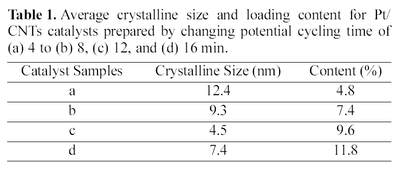
Average crystalline size and loading content for Pt/CNTs catalysts prepared by changing potential cycling time of (a) 4 to (b) 8 (c) 12 and (d) 16 min.
content of catalysts was proportional to the sweep time.
The average crystalline sizes of the CNTs-supported catalysts as a function of sweep time are shown in Table 1. In the case of the changed sweep time, the smallest crystalline size was obtained at 12 min. By increasing the sweep time over 12 min, the crystalline size was increased, reflecting some growth or a somewhat aggregation of particles. It was concluded that the 12 min is the best condition for obtaining the smallest crystalline size. It was considered that particle nucleation is not as efficient as particle growth at the initial stage of electrodeposition. After 12 min plating, the particle nucleation was efficient enough to produce a new generation of small particles, resulting in the decrease of the average crystalline size. Although more precise nucleation and growth mechanisms are necessary for Pt nanoparticles, it was found that the smaller crystalline size could be obtained after an initial activation state.
3.2. Electrochemical properties of catalysts
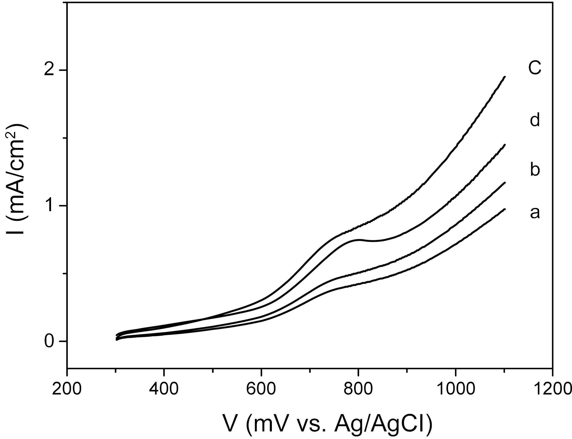
The electrochemical properties of the catalysts were investigated by current-potential curves in 1M CH3OH+0.5M H2SO4 aqueous solution. Fig. 2 shows the curves of the CNTs-supported catalysts, representing the electrochemical behavior of methanol oxidation. The electrochemical activities of catalysts prepared by a changed sweep time were studied. In the case of 4 min sweep time, the catalyst curve showed a slight oxidation peak at 760 mV and a small current density. In the case of 8 min sweep time, the curve showed a slight oxidation peak at 750 mV and an increased current density. Catalyst prepared by 12 min sweep time showed the highest current density of 1.5 mA/cm2 at 1000 mV and lowest onset potential (i.e., a potential of oxidation current to begin to rise) of ~600 mV among the samples. In the cases of 16 min sweep time, the current density of the catalyst was degraded. These results indicated that the sweep time over 12 min could have a negative effect on the electrochemical activity of deposited catalysts.
The electrochemical activity was increased with increasing cycling time, reaching the maximum at 12 min, and then was decreased at 16 min. However, the catalysts showed an increased Pt content, in proportion to the cycling time, to 16 min. That is, the Pt content was the highest when the plating time was 16 min, even though the optimal plating time was 12 min. This puzzling result was considered to have originated
from the catalyst’s crystalline size and morphology structures. These electroactivity changes as a function of electrochemical condition were inversely proportional to the size of the nanoparticle catalysts, indicating that the higher electroactivity could have been enabled by the decreasing crystalline size of nanoparticle catalysts, resulting in the increase of the efficient specific surface area for an electro-catalytic reaction.
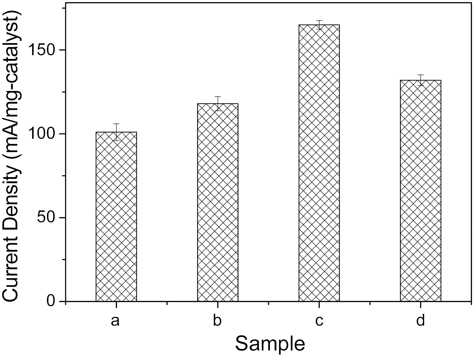
Fig. 3 shows the weight-based specific current densities at 1000 mV potential of the prepared catalysts, according to the above conditions. At the 12 min sweep time, as shown by graph, the specific current densities of the catalysts showed the highest value, 165 (mA/mg). Over 12 min sweep time, the current density was somewhat degraded. Therefore, it could be deduced that the electroactivity of catalysts prepared by electrodeposition is strong dependent on the electrical signal condition manifest in the plating time for potential cycling methods.
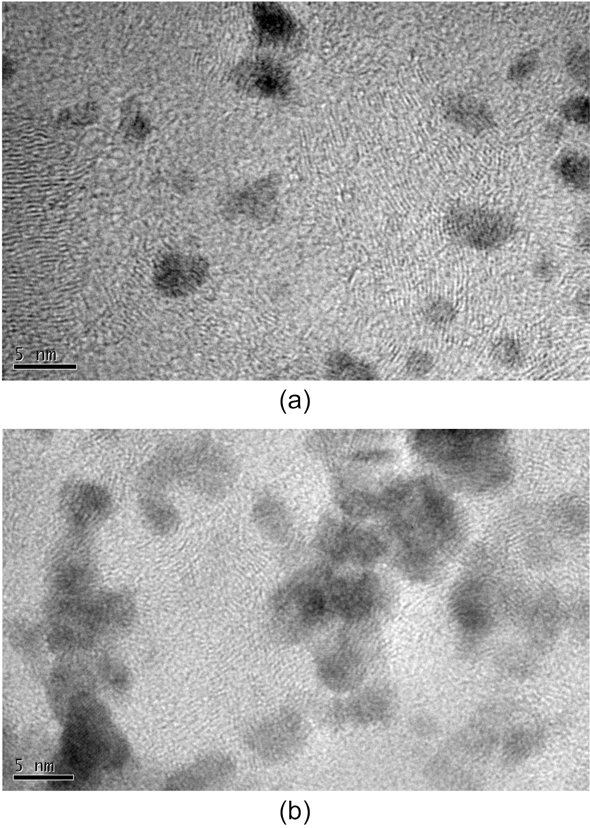
Fig. 4 shows TEM images for the obtained metal catalysts deposited on carbon nanotubes. Pt/CNTs prepared by 12 min cycling showed the small nanoparticles having an average particle size of 4.5 nm. Also, it shows no aggregated phenomena, meaning good dispersion morphology of particles. Considering this together with the previous catalytic activity, the good dispersion ability also is an important factor for the better catalytic activity, because better dispersion brings the larger available surface area for an electrochemical reaction.
In the case of (b) Pt/CNTs prepared by 18 min, the TEM image shows some aggregated particles morphology. In comparison to the above case, the particle population is large,meaning the higher level of deposited contents. However, the particle size is larger and the particle aggregation trend is severe. As a result, the large particle size and the aggregation morphology could bring the decrease of the effective surface area for an electrochemical reaction. Consequently, the particle size and the morphology are critical factors for catalyst activity for methanol oxidation.
The electrochemical deposition and characterization of CNTs-supported Pt catalysts were investigated. Pt particles as catalysts were electrodeposited onto CNTs by potential cycling methods. Concerning the effects of changed sweep time, the smallest crystalline size was obtained at 12 min sweep time. By increasing the sweep time to 16 min, the crystalline size was further increased. The loading content was dependent on the sweep time. The smallest nanoparticles, of 4.5 nm, were obtained by potential cycling methods after 12 min plating time. At the beginning of the deposition, the particle nucleation was not efficient enough to produce a new generation of small particles, resulting in the large average crystalline size. In viewpoint of electroactivity of deposited catalyst by potential cycling method, electroplating for 12 min brought the higher electrochemical activity. These results correlated to the fact that crystalline size and aggregation morphology of catalysts, providing a larger available catalyst surface area for methanol oxidation. The catalysts by the potential cycling showed the specific current density of 165 (mA/mg) at 12 min deposition time.