Heat release from the electronic devices by excellent thermal conduction is involved in the use of heat sink to dissipate heat from an electronic package, the operation of heat exchanger, the melting of ice on the runway, the cooking and the numerous industrial processes. For effective thermal conduction, thermal interface materials or thermally conductive composites must have excellent thermal conductivity across which heat transfer occurs with the low contact resistance. Without good thermal contacts, the use of a thermal conductive material is just cost-consuming [1]. Most polymer resins are known to be thermal insulators. In insulators, heat transport is governed by the motion of free particles, called “phonon”. For insulating materials, heat transfer by the mobile electrons is ignored which dominates the thermal conductivity of metals [2]. Thermally conductive polymer composites offer the new, easy and economic way to improve the heat dissipation from the heat source. Thermally conductive polymer composites have much potential than the traditional thermally conductive metals in terms of the good resistance to corrosion, light and processibility for their purposes [3].
Beside thermally conductive polymeric solid composites,thermal interface materials (TIM) as the excellent thermal conducting materials play very important roles in electronics [4]. Today, as the electronic products are chasing light, pocketsized and large scale integration, thermal problems occurring inside of products bring about more troubles [5]. Thermal management of these products is very important for design, packaging and housing of goods. Generally, commercialized thermal conductive pads or films are using the metal powder or ceramic particles in the polymeric matrix for using their high thermal conductive properties [1]. High performance materials need the superior thermal conducting behavior for their high exothermic character.
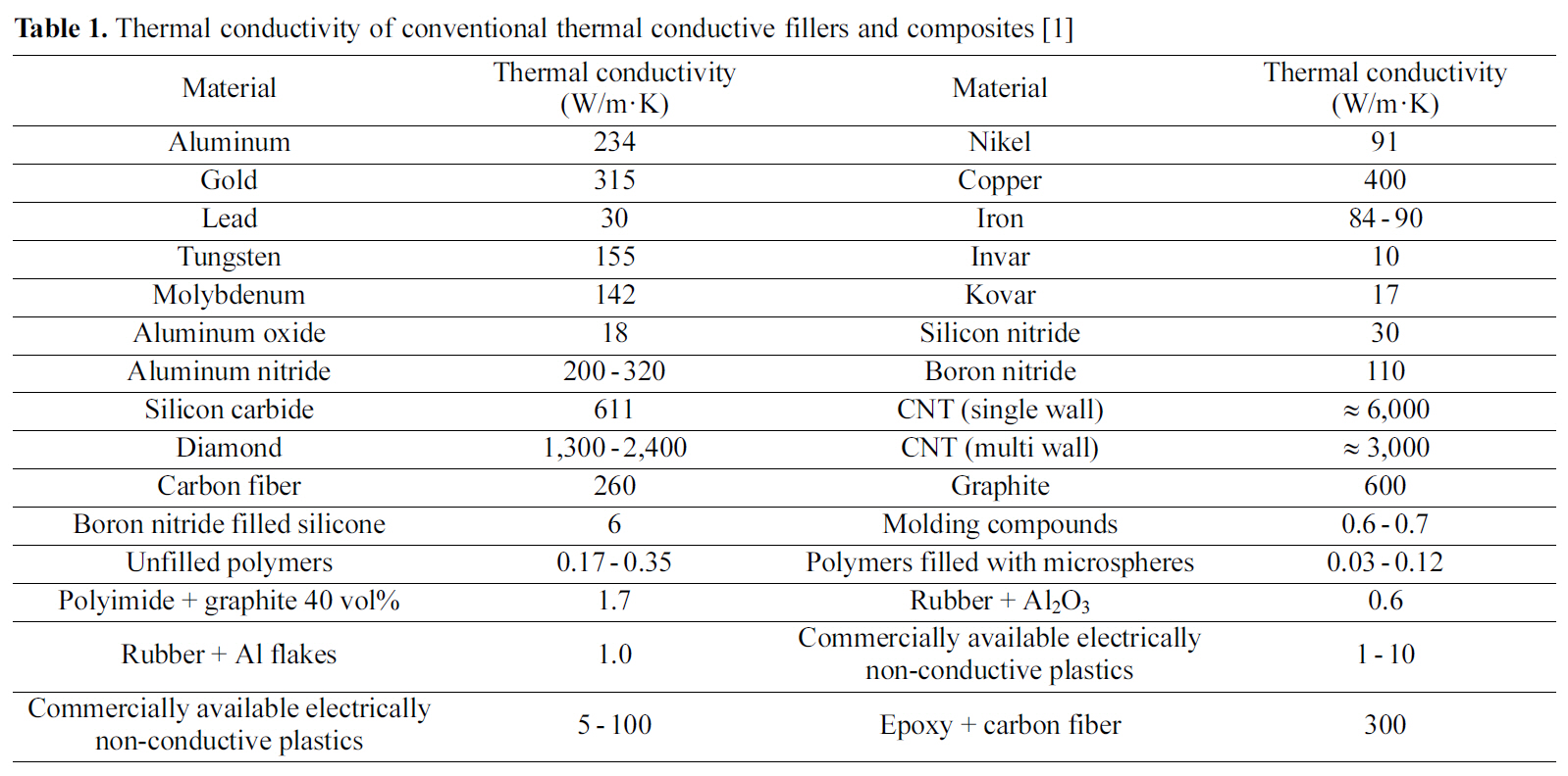
For improving the thermal conductivity of a polymeric material, polymer matrices are usually filled with the thermally conductive fillers like metal powders, ceramic powders and carbon-based materials. General thermal conductivity of polymer resins is in the range from 0.1 to 0.3W/m·K. Some common fillers for enhancing thermal conductivity are 234W/m· K for aluminum, 400W/m ·K for copper and 600W/m ·K for graphite. In Table 1, the thermal conductivities of conventional thermally conductive fillers are listed [1]. For using the polymer composites as a thermal interface material, the thermal conductivity of the fabricated composites should have approximately 1 to 30W/m·K [6,7].
Many researchers have used the metal oxides, metals and ceramics such as alumina (Al2O3), diamond, silicon carbide (SiC), and zinc oxide (ZnO) as the thermal dissipative filler of the composite materials [1]. Goh
[Table 1.] Thermal conductivity of conventional thermal conductive fillers and composites [1]
Thermal conductivity of conventional thermal conductive fillers and composites [1]
conductivity of silicone rubber. Thermal conductivity of the prepared composite was improved with alumina particles with a smaller diameter at the same volume fraction [9]. Kim
Carbon-based fillers are known as very ideal thermal conductive fillers for polymer composites because they have a higher thermal conductivity, excellent corrosion resistance, and a lower thermal expansion coefficient than metals. When the matrix and filler are both carbon materials, it is called carboncarbon composite. The carbon-carbon composite shows very high thermal conductivity and it is most suitable to use as heat sink. But the carbon-carbon composite is very expensive, so the application of carbon-carbon composites to industrial purpose is confronted with difficulties. For this reason, many researchers are working on the development of cheap polymer composites using carbon-based materials as the filler.
Graphite, carbon fiber, diamond and carbon nanotube are frequently explored as the thermal conductive fillers in polymer-carbon composites. After the discovery of carbon fiber (CNF), most of the works are focused on the use of CNF as thermal, electrical, and mechanical reinforcing filler to improve the polymer characteristics [16,17]. Recently, an article shows the 150% of thermal conductivity enhancement with 1 wt% of CNF in polymer matrix [16]. But the
polymer-CNF composite still lacks the models for predicting the effective thermal conductivity for their unusual structure.
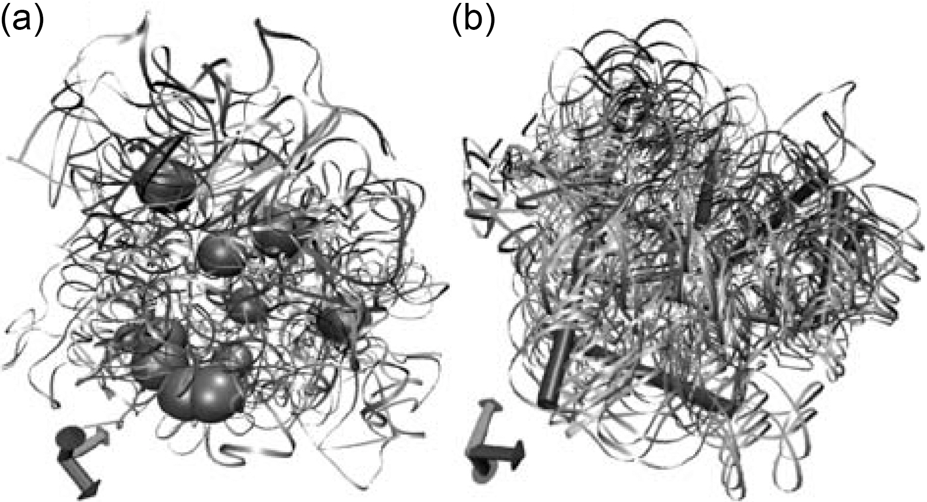
A significant amount of work has been conducted by using the 1-dimensional carbon fillers like carbon nanotube (CNT) and carbon nanofiber (CNF). These fillers enhance not only the thermal conductivity, but also the electrical, and mechanical properties. 3-Dimensional microstructure of the nanofiller loaded polymer composites is shown in Fig. 1 [18]. When the nanofillers are dispersed in the soft polymeric matrices, mechanical properties of the composites can be enhanced by a reinforcing effect from transferring the loads. When the polymer composites filled with spherical filler (aspect ratio of the particle is equal to unity), the modulus of the composite depends on the modulus, density, size, shape, volume ratio, and number of the incorporated particles. The 1-dimensional filler may connect more polymer chains and afford more effective load transfer, leading to an improvement of mechanical properties. Upon adding a critical volume fraction of 1-dimensional filler, the filler stretches and perturbs the polymer matrix, generating elongated domains that are reinforced by these fillers [19]. 1-Dimensional fillers can easily transfer the loads or reduce it than spherical fillers. Here, the uniform dispersion of CNT or CNF in the polymer matrix is the main concern. Welldispersed polymer composites filled with CNT or CNF can be achieved by using the fine twin-screw extrusion, surfactant, oxidation of fillers and incorporation of functional groups on the surface of the fillers.
2. Carbon Nanotube (CNT) Incorporated Polymer Composites
2.1. Thermal conductivity of CNT-polymer composites
CNT incorporated polymer composites with enhanced properties have been widely explored in the materials science and engineering, especially in the reinforcing and conducting behavior of the composites. Recently, ultra-high thermal conductive nature of CNT has gained much attention to use CNT as thermally conductive filler. With the expensive manufacturing cost and limited production, initially, the use of CNT as the thermal conductive filler was rare. But the reduced unit cost for manufacturing and the mass production of CNT with the technological development lead the massive use of CNT as the thermal conductive filler. Because CNT exhibits the extremely high thermal conductivity and mechanical property, a great attention has been paid to the application of CNT in electronic devices [20-23]. As the electronic devices need the multifunction and high performance in a small size, the heat dissipation from the products has become more important. For example, a small difference in operating temperature in the order of 10 ~ 15℃ can result in a two-fold reduction in the life time of the electronic devices [24]. CNT has the one-dimensional unique structure which enables the composites filled with CNT to have low percolation threshold concentrations [25,26]. By using this characteristics, CNT incorporated composites show the thermal conductivity enhancement at low concentrations [27,28].
Theoretically and experimentally, the thermal conductivity of CNT is about 3,300 and 6,600W/m·K for multiwall and singlewall CNT, respectively. One-dimensional structural characteristics of CNT may promote the thermal conduction behavior of the polymer-CNT composites with a low concentration of CNT incorporation [29,30]. Theoretically, six-fold of thermal conductivity enhancement of composite can be achieved by 0.1 wt% of CNT incorporation to the polymer matrix. But experimental results show that it is impossible with current techniques [31-34].
2.2. Models for predicting thermal conductivity of CNTpolymer composites
Since CNT has a very large aspect ratio and anomalous thermal conductivity, the prediction of the thermal conductivity of CNT incorporated polymer composites from the existing theoretical model is not possible [16]. Nan
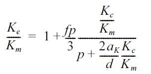
where Kc, Ke, Km, f, p, and d are thermal conductivity of CNT, effective thermal conductivity of the composite, thermal conductivity of matrix, volume fraction of nanotube, aspect ratio of CNT, and diameter of CNT, respectively. And the Kapiza radius (aK) is defined by
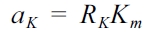
For nanotube composites, aK is 16~40 nm when Km is 0.2~0.5W/m·K and RK is 8×10⁻⁸ m·K/W. By using equation (1), Hong
heat dissipation. CNT easily forms the self-aggregated clusters in the polymer matrix and the clusters disturb the heat conduction within the polymer matrix. Also the surface resistance of the polymer-CNT is very important to heat penetration. Hong
2.3. Experimental review on thermal conductivity of CNT-polymer composites
Bryning
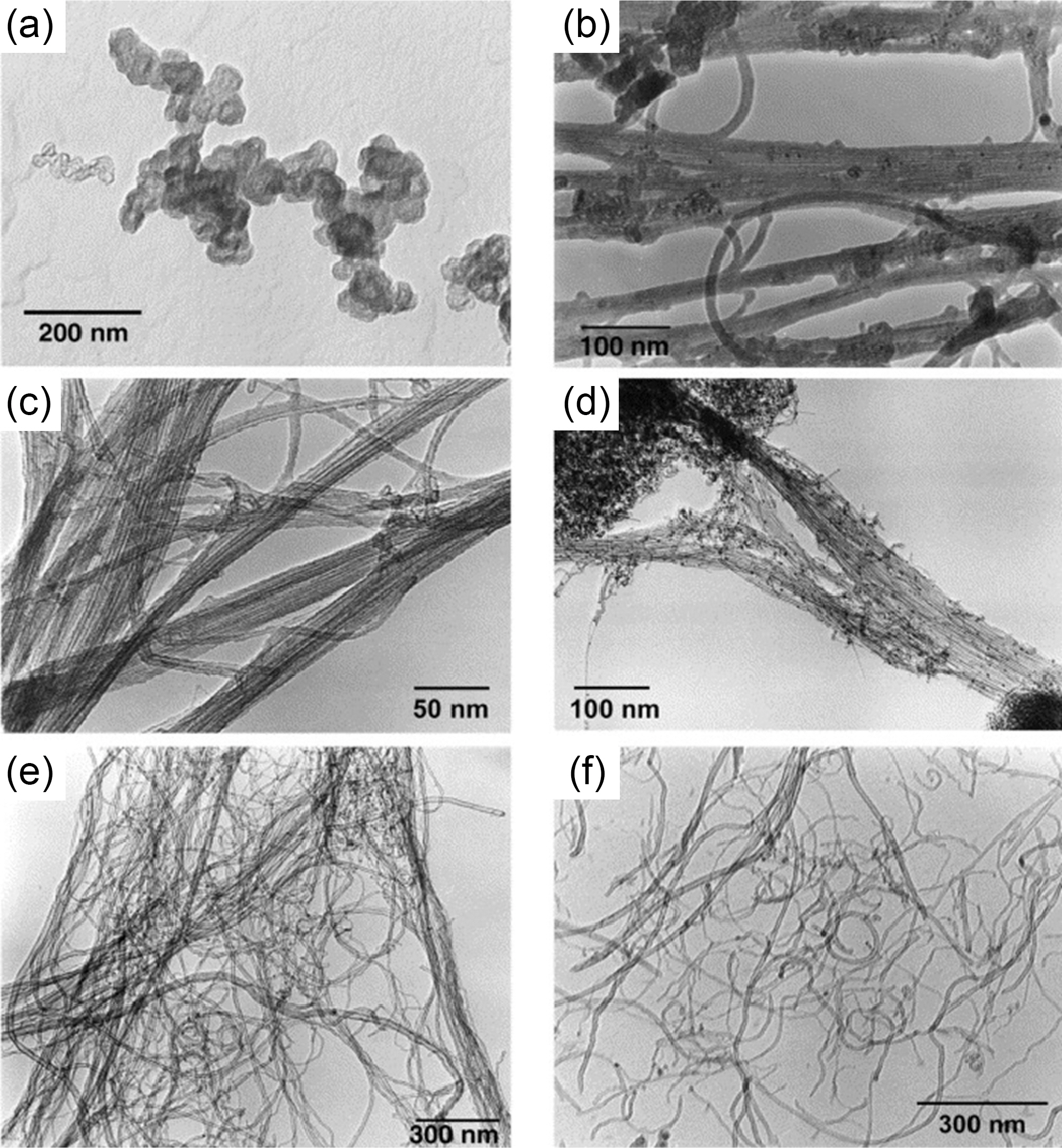
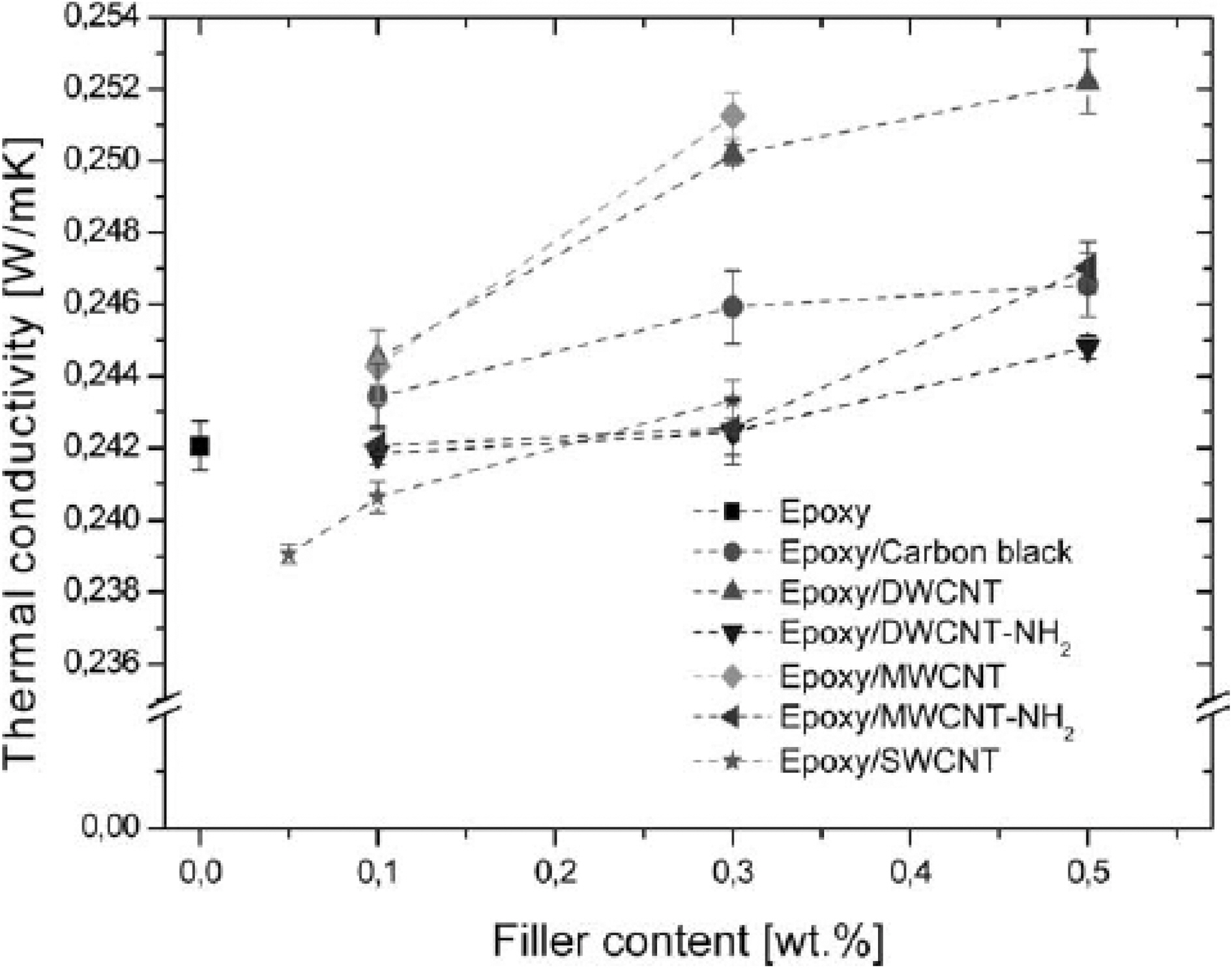
surface-functionalization (-NH2) in epoxy matrices [31]. The transmission electron microscopy (TEM) images of the fillers used in the work are shown in Fig. 5. Because the interfacial adhesion between the CNT and epoxy matrix influences to the phonon conduction, the experimental results showed the composites containing amino-functionalized CNT had lower thermal conductivity than pristine CNT incorporated composites due to reduced interfacial adhesion (Fig. 6). Huang
Song
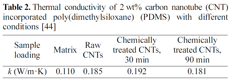
Thermal conductivity of 2 wt% carbon nanotube (CNT) incorporated poly(dimethylsiloxane) (PDMS) with different conditions [44]
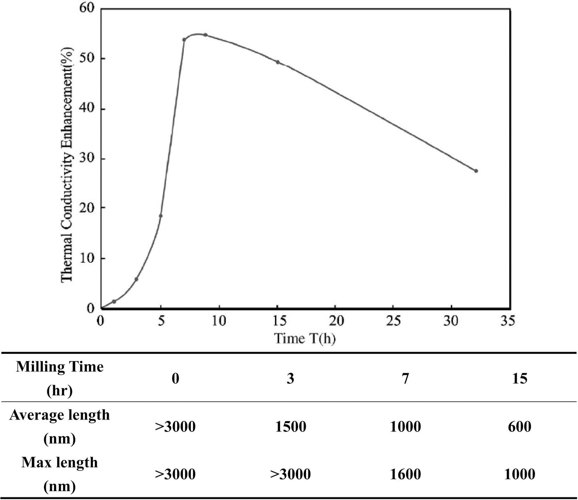
conductivity from decreased aspect ratio.
Liu
resistance and decreases intrinsic CNT conductivity by defect generated during the acid treatment. Yu
3. Carbon Nanofiber (CNF)/Graphite Incorporated Polymer Composites
3.1. Thermal conductivity of CNF-polymer composites
In recent years, nanomaterials are increasingly being used in polymer resins to enhance a variety of properties without sacrificing any properties of the polymer. For example, CNT and carbon nanofiber (CNF) have very high thermal and electrical conductivities with the unusual 1-dimensional structures. Especially, CNF reinforced thermoplastic laminates have been used in aerospace sector due to their excellent heat stability, mechanical property, and low flammability [46]. In principle, proper alignment of the nanofillers can give the desired directional properties, but it is not always easy to obtain such alignment with the normal polymer processing methods of extrusion and injection molding. CNF and CNT have same 1-dimensional structures and both are fabricated by the catalytic decomposition of aliphatic hydrocarbons. But they are different in the diameter (CNF: ~100 nm, CNT: 1~10 nm) and their thermal conduction properties. Recently, CNF has become readily available in
large quantities and at a price that is significantly lower than that of CNT. So, the use of CNF as the filler in the polymer matrices has much potential in industrial applications.
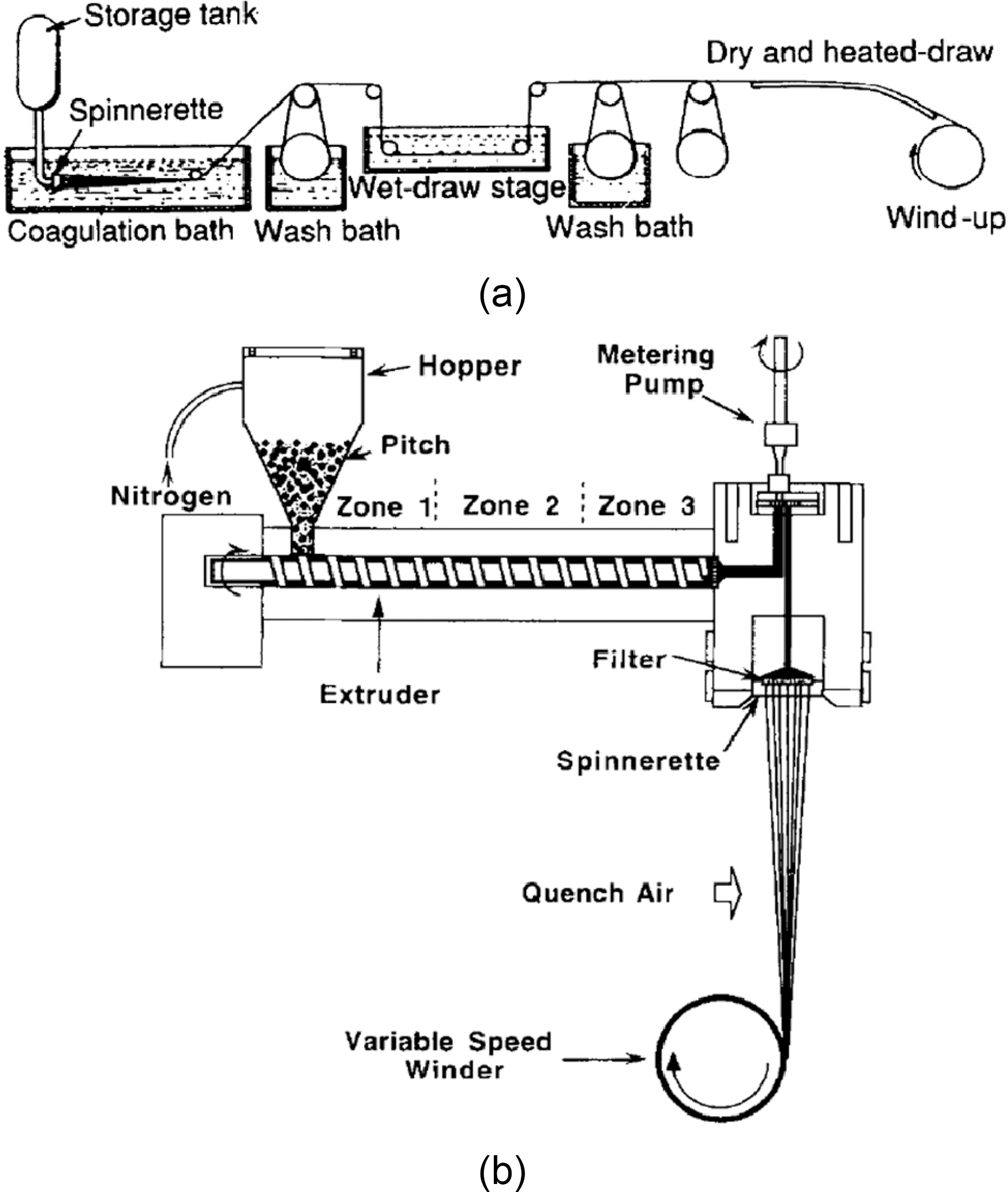
In 1960, the high performance carbon fiber was firstly commercialized by Union Carbide. Most of the CNFs are produced by converting a carbonaceous precursor into fiber form, then crosslinked. After the carbonization at a temperature from 1200 to 3000℃ in an inert condition, final carbon fiber products are fabricated [47]. Most of the carbon fibers can be classified into two main base materials, namely, poly(acrylonitrile), PAN, precursor carbon fiber and pitch precursor carbon fiber. The schematic process for producing the PAN-base and pitch-base fibers is shown in Fig. 11(a) and (b). When preparing the PAN-base fiber, the rate of fiber formation is controlled by the solution concentration, the concentration of coagulation bath, the temperature of the bath, the speed of wind up, and so on. Like PAN-base fiber, the pitch-base fiber formation can be controlled by adjusting parameters.
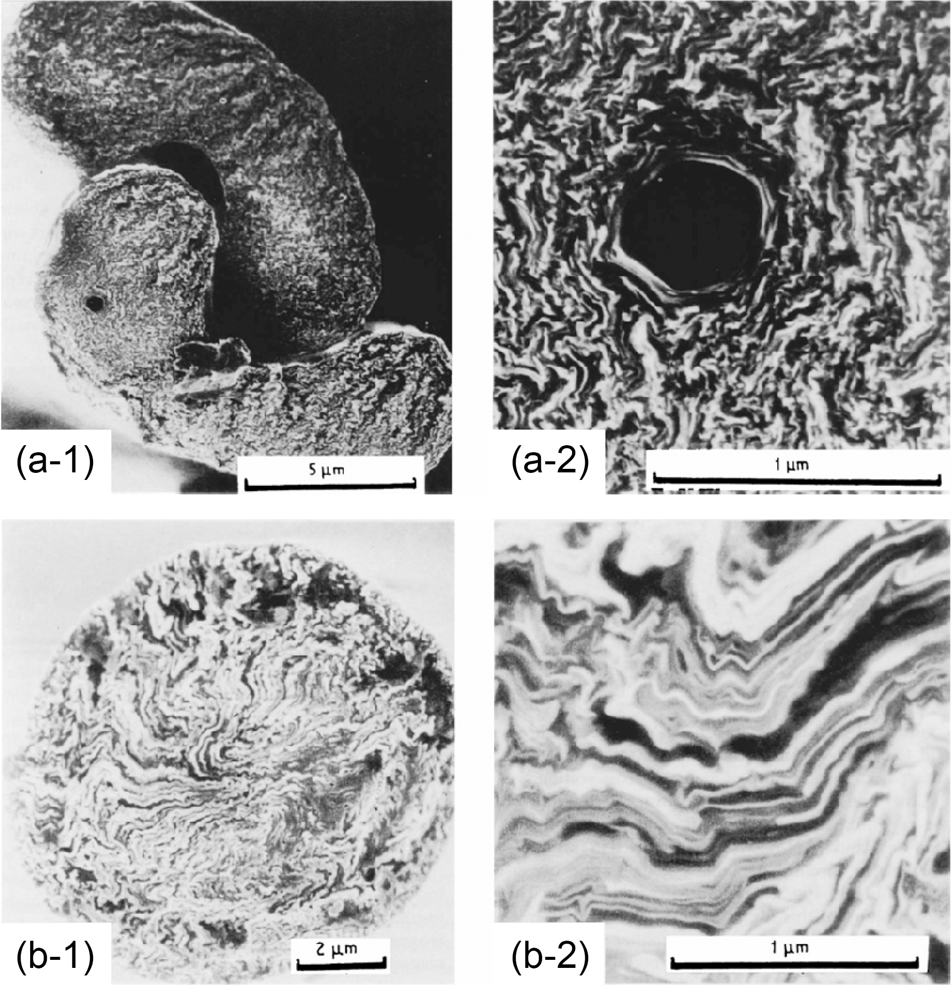
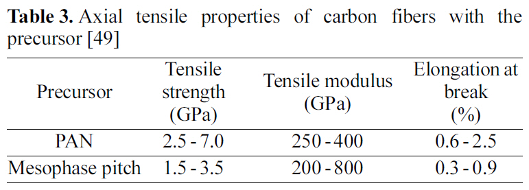
Carbon fiber offers the highest tensile strength and modulus out of all reinforcing fillers. In Table 3, typical properties of different two carbon fibers are compared. Carbon fibers do not show the stress failure, stress corrosion or stress rupture at room temperatures, as other fibers do(polymer or glass fiber) [48]. Because PAN-based CNF consists of particle-like structure and small crystals in comparison with pitch-based CNF, PAN-based CNF has
[Table 3.] Axial tensile properties of carbon fibers with the precursor [49]
Axial tensile properties of carbon fibers with the precursor [49]
higher tensile and compressive strength than pitch-based CNF. Due to these characters of two types of CNF, PANbased CNF generally shows lower thermal conductivity than that of pitch-based CNF. The scanning electron microphotographs of the cross-section of PAN-based CNF and pitch-based CNF are represented in Fig. 12.
The thermal conductivity of CNF is not exactly explored, but it is thought to be very high. The thermal conductivity value of CNF might be in the range of the thermal conductivity of the graphite (600W/m·K) and the corresponding value of MWCNT (3,300W/m·K). Similarly to CNT, the thermal conductivity of the polymer composite can be significantly increased by the addition of a small concentration of CNF with their unusual 1-dimensional structure without the adverse effect of the polymer matrix. Many researchers have investigated the effect of CNF on the thermal conductivity of CNF filled polymer composites. But the interface resistance between the polymer and CNF has not been established yet. So, the enhancement of the thermal conductivity by the addition of CNF is much lower than our expectation [49]. It is for this reason that the thermal conductivity of particulate composites is not sensitive to the thermal conductivity value of the filler, provided that the ratio of the filler to matrix thermal conductivity is large [50]. To increase the interfacial interaction between the CNF and the polymer matrix, acid treatment of the fibers has been attempted [51].
3.2. Experimental review on thermal conductivity of CNFpolymer composites
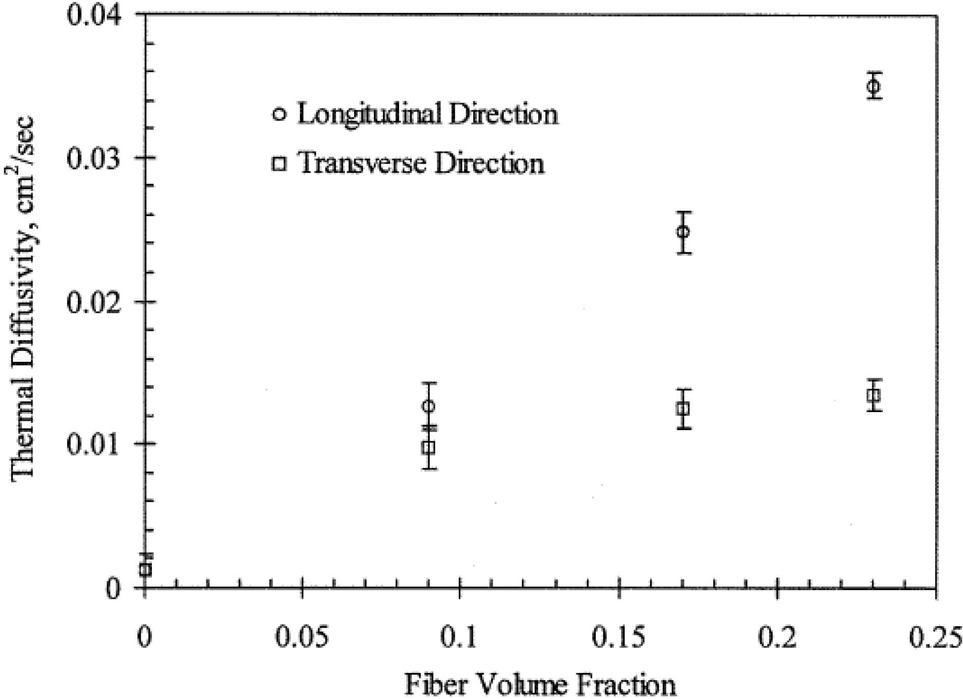
Kuriger
[Table 4.] Thermal conductivity of polyimide/carbon nanofiber composites [54]
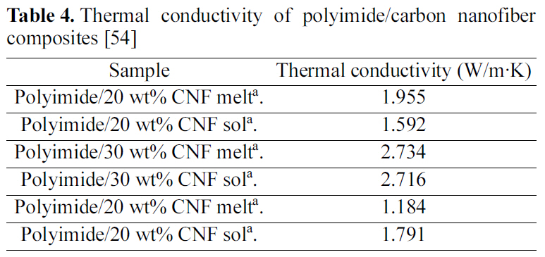
Thermal conductivity of polyimide/carbon nanofiber composites [54]
orientation of CNF in the polyimide matrix was achieved via melt mixing and the thermal conductivity of the composite was higher with the melt mixing process. But when CNF was not aligned, the better dispersion of CNF in polymer matrix
was observed in the process via solution mixing. Table 4 shows the thermal conductivity of the polyimide-CNF composites. The thermal conductivity of the composite was significantly increased with the alignment of CNF.
Recently, many researchers made an effort on hybrid filler systems using CNT and CNF together. Kim
Herein, the thermal conductivity of 1-dimensional carbonbased filler incorporated polymeric composites is reviewed.1-Dimensional carbon based materials such as carbon nanotubes and carbon fibers are frequently mixed with polymer resins in efforts to increase the thermal conductivity of the polymer composites. For their unique structure and excellent thermal transportation properties, the thermal conductivity of the composite can be significantly increased with the small concentration of the fillers. Commonly, the thermal conductivity of 1-dimensional filler incorporated composites was found to be much higher in the longitudinal direction due to axial alignment of nanotubes and fibers. And nanotubes and fibers can easily generate the clusters in a polymer matrix with the curvature characters of the fiber. Also, the thermal resistance between the polymer and fibrous filler prevents the penetration of the phonons through the interface. So the dispersion of the nanotubes/fibers in the matrix and thermally connectable techniques are very important for enhancing thermal conductivity of the composites.
By using some important models for predicting the thermal conductivity of composites, CNT and CNF filled nanocomposites show the very high thermal conductivity enhancement than any other inorganic fillers. However, in reality, the increment of a thermal conductivity is not high enough than our expectation. In order to predict the thermal conductivity of 1-dimensional fillers incorporated composites, the degree of the dispersion of nanotubes/fibers and the thermal resistance between the polymer and filler must be taken into account.
Thermal management of the materials becomes more important with the development of the electronic devices, aerospace technology, power generation, thermo coatings, and so on. Therefore, the pace to exploit these materials must be expedited and the exploration to find the potential uses must be continued such as for LED application.

![Thermal conductivity of conventional thermal conductive fillers and composites [1]](http://oak.go.kr/repository/journal/10413/HGTSB6_2010_v11n4_347_t001.jpg)
![3-D schematic demonstration of nanocomposite systems: (a) with spherical fillers (such as Al2O3 and SiO2) (b) with rodlike filler (such as clay or carbon nanotubes) [18].](http://oak.go.kr/repository/journal/10413/HGTSB6_2010_v11n4_347_f001.jpg)
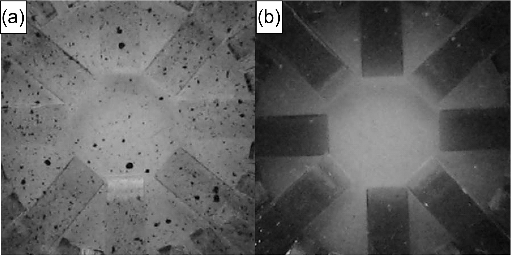
![Carbon nanotube dispersion state of (a) raw and (b) masterbatched multiwall carbon nanotube (MWCNT)/poly(dimethylsiloxane) (PDMS) composites at 0.1 phr MWCNT [37].](http://oak.go.kr/repository/journal/10413/HGTSB6_2010_v11n4_347_f002.jpg)
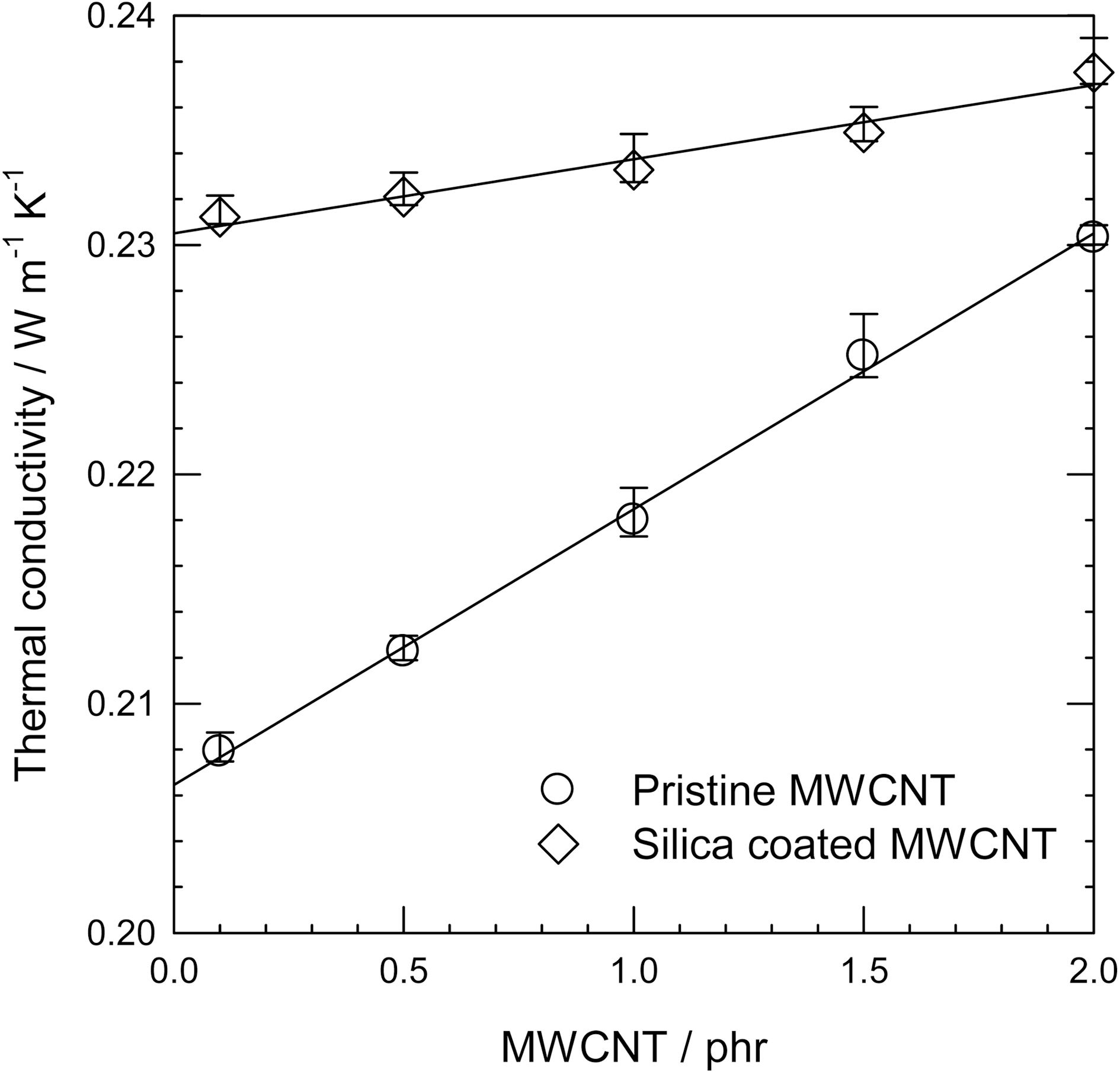
![Thermal conductivity of raw MWCNT and silica-coated MWCNT incorporated PDMS nanocomposites [38].](http://oak.go.kr/repository/journal/10413/HGTSB6_2010_v11n4_347_f003.jpg)
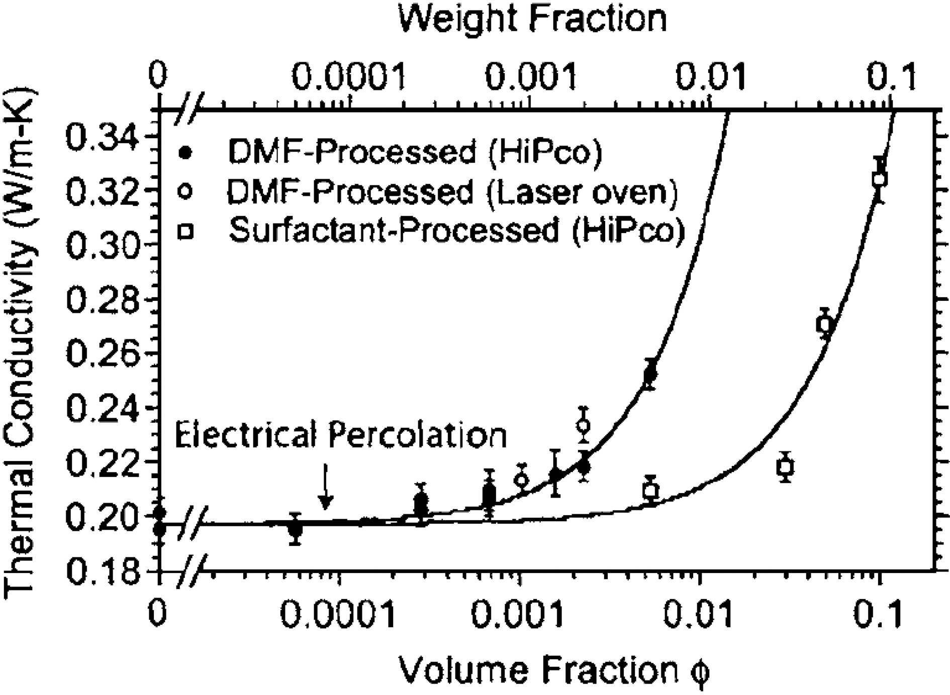
![Thermal conductivity of SWCNT dispersed epoxy nanocomposites using DMF and surfactant as dispersant [28].](http://oak.go.kr/repository/journal/10413/HGTSB6_2010_v11n4_347_f004.jpg)
![TEM-images of the nanofillers: (a) carbon black (b) singlewall CNT (c) doublewall CNT (d) amino-functionalized doublewall CNT (e) multiwall CNT and (f) amino-functionalized multiwall CNT [31].](http://oak.go.kr/repository/journal/10413/HGTSB6_2010_v11n4_347_f005.jpg)
![Thermal conductivity vs. filler contents with different fillers [31].](http://oak.go.kr/repository/journal/10413/HGTSB6_2010_v11n4_347_f006.jpg)
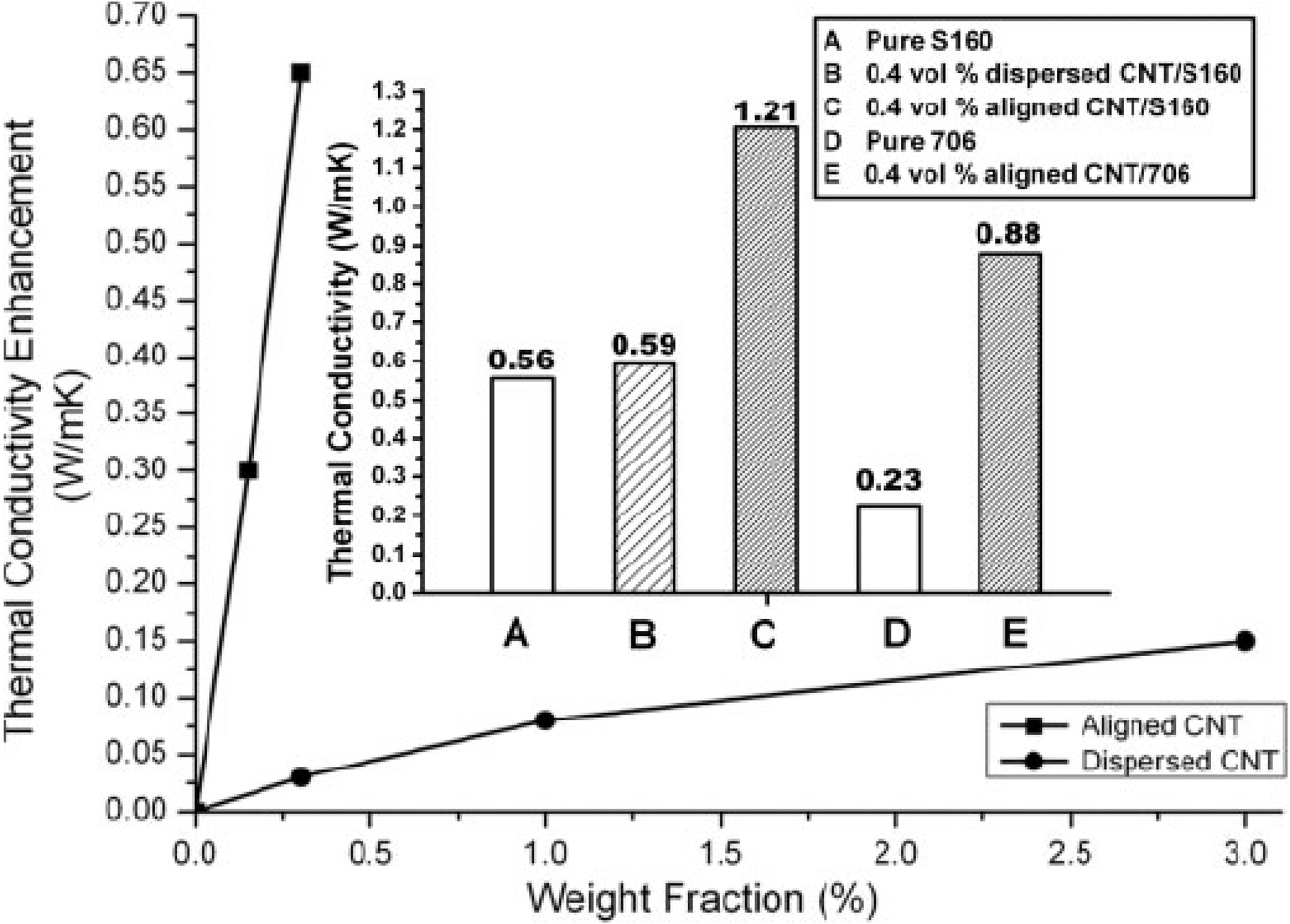
![Thermal conductivity as a function of weight fraction of CNT [40]. 706: low thermal conductive silicone rubber (0.23W/m·K) and S106: thermally conductive silicone elastomer (0.56W/m·K)](http://oak.go.kr/repository/journal/10413/HGTSB6_2010_v11n4_347_f007.jpg)
![Thermal conductivity enhancement with different ballmilling times at 0.64 wt% CNT [41].](http://oak.go.kr/repository/journal/10413/HGTSB6_2010_v11n4_347_f008.jpg)
![Thermal conductivity of 2 wt% carbon nanotube (CNT) incorporated poly(dimethylsiloxane) (PDMS) with different conditions [44]](http://oak.go.kr/repository/journal/10413/HGTSB6_2010_v11n4_347_t002.jpg)
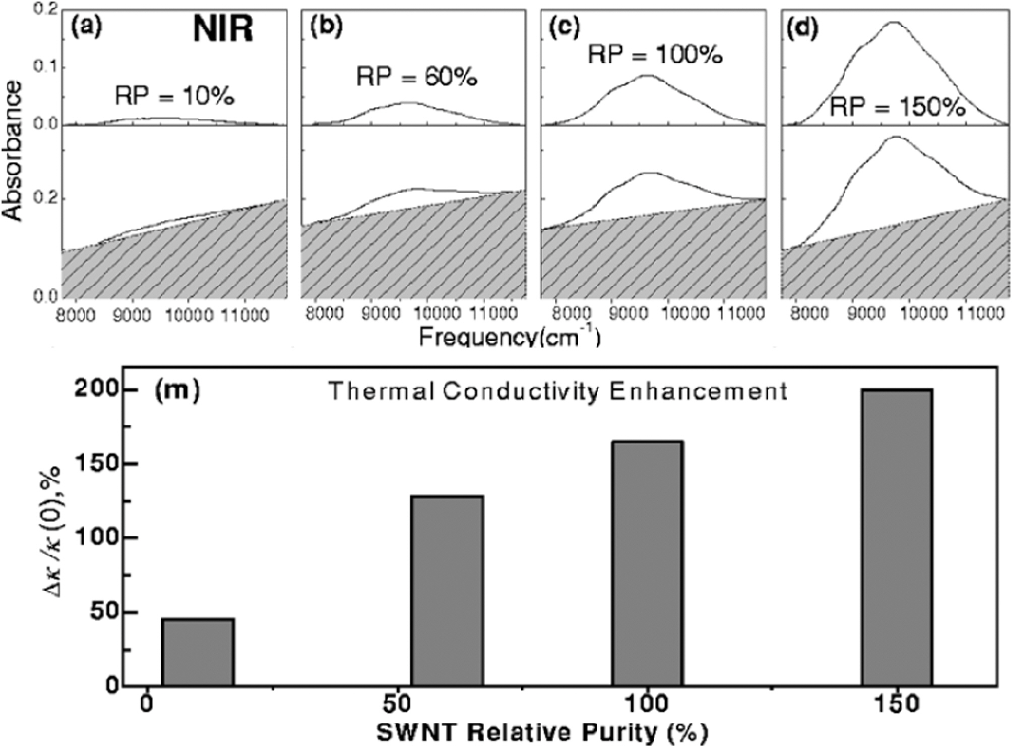
![NIR spectroscopy of four SWCNT fractions; (a) raw (b) acid treated (c) low speed centrifuged and (d) high speed centrifuged CNTs and thermal conductivity enhancement as a function of the purity of CNT [44].](http://oak.go.kr/repository/journal/10413/HGTSB6_2010_v11n4_347_f009.jpg)
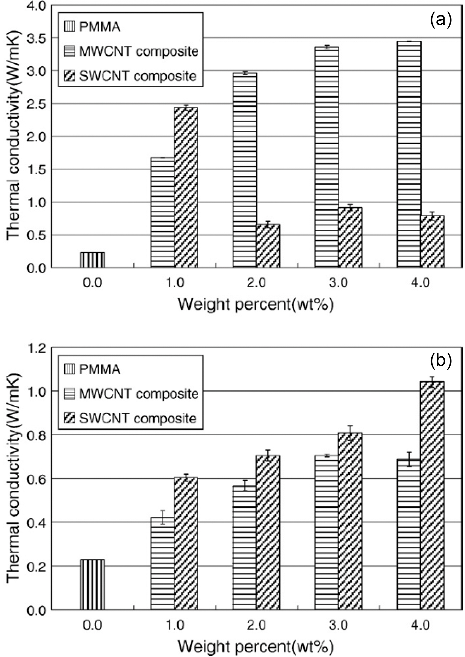
![Thermal conductivity of (a) raw-CNT and (b) purified CNT incorporated PMMA-based composites [45].](http://oak.go.kr/repository/journal/10413/HGTSB6_2010_v11n4_347_f010.jpg)
![Schematic of the process used to produce (a) PANbased and (b) pitch-based CNF [47].](http://oak.go.kr/repository/journal/10413/HGTSB6_2010_v11n4_347_f011.jpg)
![Axial tensile properties of carbon fibers with the precursor [49]](http://oak.go.kr/repository/journal/10413/HGTSB6_2010_v11n4_347_t003.jpg)
![SEM pictures of (a) PAN-based and (b) pitch-based CNF. Terminations (-1) and (-2) refer low and high resolutionrespectively [48].](http://oak.go.kr/repository/journal/10413/HGTSB6_2010_v11n4_347_f012.jpg)
![Thermal diffusivity results in the longitudinal and transverse directions for PP composites at various CNF volume fractions[52].](http://oak.go.kr/repository/journal/10413/HGTSB6_2010_v11n4_347_f013.jpg)
![Thermal conductivity of polyimide/carbon nanofiber composites [54]](http://oak.go.kr/repository/journal/10413/HGTSB6_2010_v11n4_347_t004.jpg)
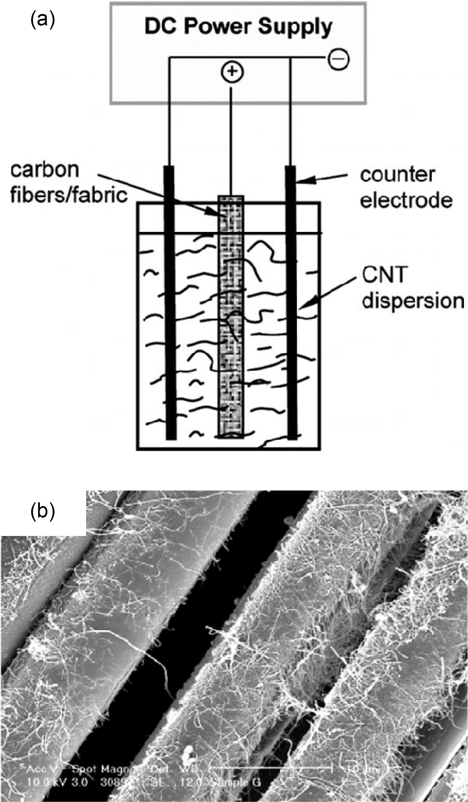
![(a) Electrophoresis process for deposition of CNT on CNF and (b) CNF with MWCNT deposited by electrophoresis [55].](http://oak.go.kr/repository/journal/10413/HGTSB6_2010_v11n4_347_f014.jpg)
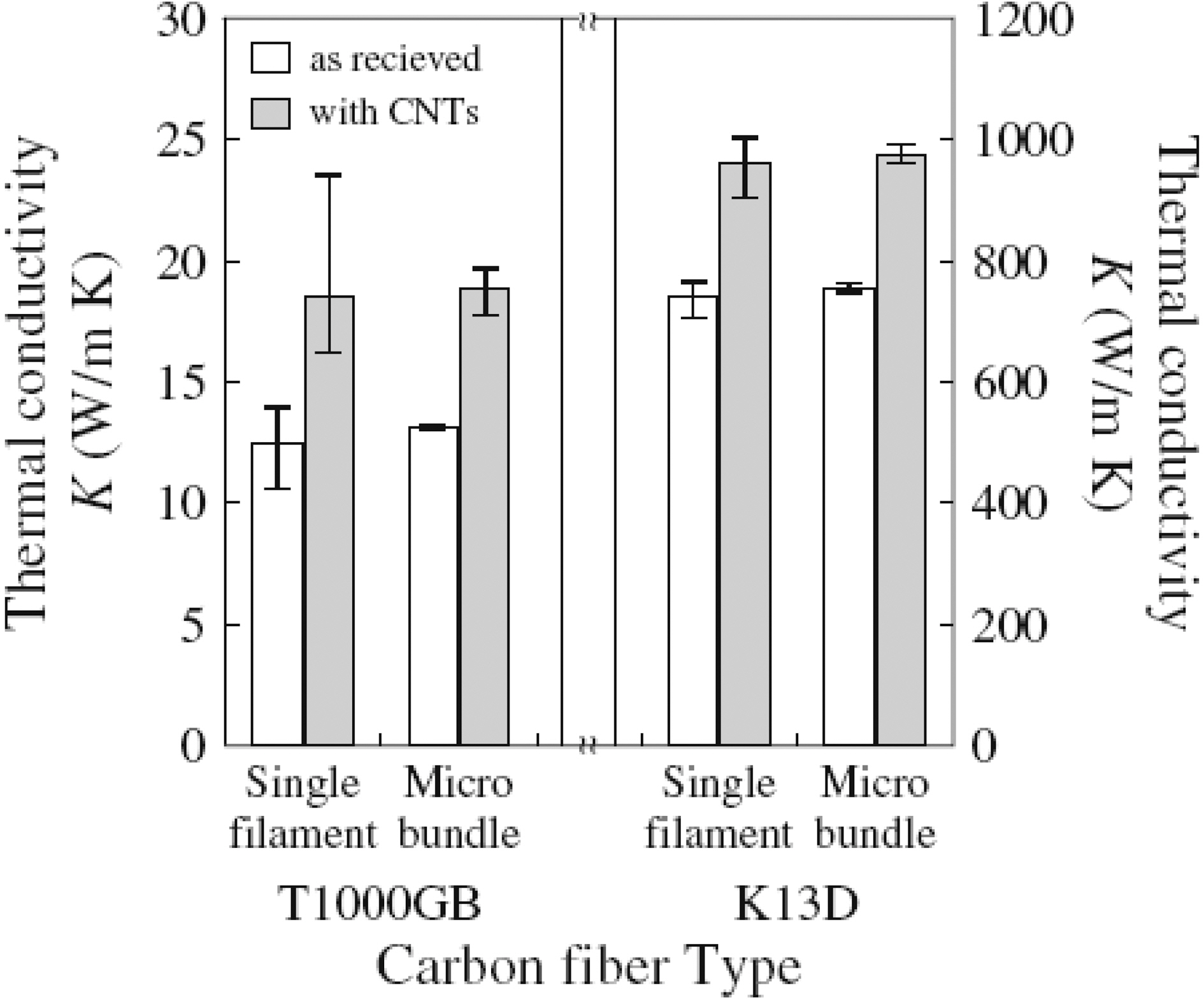
![Thermal conductivity of pristine and MWCNT-grafted PAN-based (T1000GB) and pitch-based (K13D) carbon fibers[56].](http://oak.go.kr/repository/journal/10413/HGTSB6_2010_v11n4_347_f015.jpg)