A critical issue for the development of nanotechnology is the ability to understand, to model, and to simulate the behavior of these nano structures and to make the connection between nano structure properties and their macroscopic functions. Material modeling and simulation aid in understanding this process, help in setting objectives that guide laboratory investigation, and assist in setting controls on material structures, properties, and processes for physical implementation. These capabilities are vital to engineering design at the component and systems levels [1-6].
Nanolayer reinforcement of composite materials can greatly improve the materials structural and physical performance, such as stiffness, heat deflection temperature, and tensile strength. It also tends to lower thermal expansion coefficient and permeation rate without adding significant weight, thereby allowing nanolayer polymers to achieve greater thermal stability (to become less flammable) and to reduce permeability (improve barrier performance) [7-10]. Nanolayer-enhanced polymers distribute internal stresses more uniformly by allowing greater dimensional latitude during the forming and shaping processes, as compared to conventional macroscale reinforcements. For example, the unparalleled ability of clay nanolayers to boost mechanical properties of an engineering polymer (nylon-6) was first demonstrated by Toyota researchers. An increase of only 4.2 wt% of clay nanolayers doubled the modulus, increased heat distortion temperatures by 80℃ (compared to pristine polymer), reduced permeability for water, and increased flame retardant properties.
Carbon-based nanomaterials have been attracting much attention during the last decade, because of their superior mechanical, electrical and thermal properties. Since the late 1990’s, research has been reported that intercalated, expanded, and/or exfoliated graphite nano-platelets could also be used as nano-reinforcements in polymer systems. The key point of utilizing graphite as a nano-reinforcement is in its ability to be exfoliated into platelets of nanometer dimensions using Graphite Intercalated Compounds (GICs). Natural graphite is abundant and its cost is low compared to the other nano size carbon materials. The graphite nanoplatelets are expected to be marketed at approximately $10-20/lb once high demand and full production is achieved. This is significantly less expensive than single wall nanotubes (SWNT) (>$45,000/lb) or vapor grown carbon fiber (VGCF) ($40-50/lb), yet the mechanical, electrical, and thermal properties of crystalline graphite flakes are comparable to those of SWNT and VGCF.
Graphene is a single layer sp2-bonded carbon sheet forming a honeycomb crystal lattice [11], first introduced by Mouras, et al. (1987) as the two dimensional (2D) form of graphite. Novoselov et al. [12,13] reported that these 2D carbon materials formed gigantic flat fullerene molecules and first described their electronic properties. Lee et al.reported a Young’s modulus of 1.0 TPa, and an intrinsic
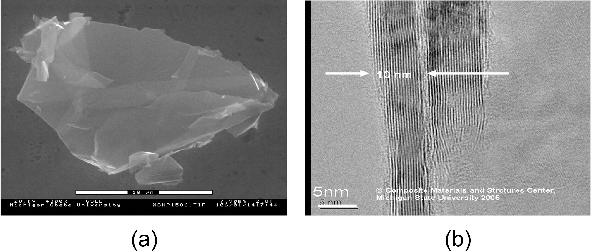
strength of 130 GPa measured by nanoindentation atomic force microscope for the monolayer graphene sheet [14]. By, those measurements, Lee categorized the graphene monolayer sheet as the strongest material ever measured. Consequently, Graphene nanocomposites are expected to perform extremely enhanced mechanical properties. Exfoliated graphite nano-platelets are new types of nanoparticles consisting of graphene stacks that are 1~15 nm thick and with diameters ranging from sub-micrometer to 100 ㎛. Exfoliated graphene nanoplatelets share chemical structures with carbon nanotubes (CNT). In fact, their edges could be easily modified chemically for dispersion enhancement in polymeric composites [15]. Fig. 1 shows the morphology of exfoliated graphene nano-platelets. These nano-platelets are typically less than 5 nm thick and can be synthesized with lateral dimensions ranging from less than 1 ㎛ to up to 100 ㎛.
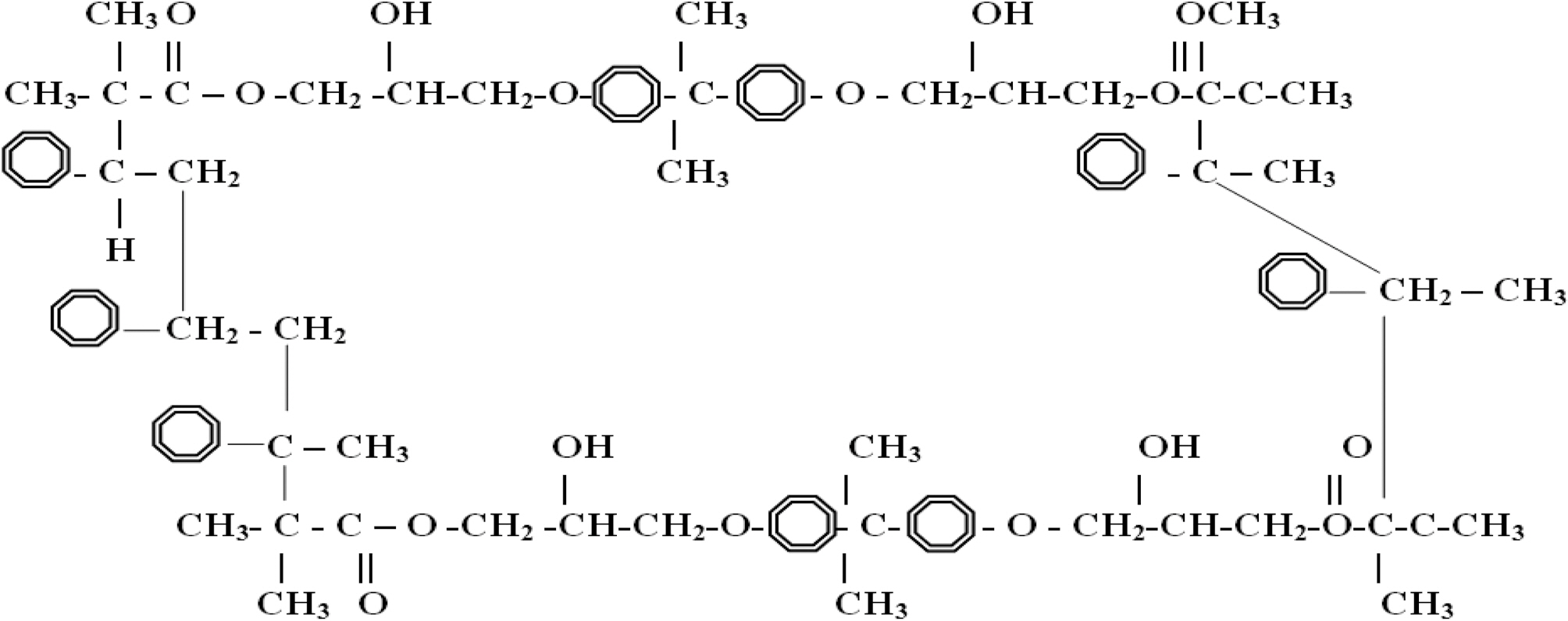
Vinylester is a copolymer thermoset resin produced by the esterification of an epoxy resin with unsaturated monocarboxylic acid. The reaction product is then dissolved in a reactive solvent, such as styrene, to (35-45) percent content by weight. Vinylester can be used as an alternative to polyester and epoxy materials in matrix or composite material because its distinctive characteristics, strength, and bulk cost lie intermediately between polyester and epoxy. Vinylester has low resin viscosity, less than polyester and epoxy [16,17]. However, the epoxy-based vinylester resins have remarkable corrosion resistance, desirable physical properties, and improved adherent properties compared to polyester due to their chemical composition, and due to the presence of polar hydroxyl and ether groups in their chemical chain. Simulated vinylester chains are 65% epoxy and 35% styrene; Fig. 2 shows a schematic of an ideal vinylester chemical chain assuming that all the epoxy had reacted.
Vinylester-resin systems have other challenge: poor resistance to crack propagation, brittleness, and large shrinkage that occurs during polymerization. Methods of incorporating nanoparticles into polymer matrices could be ex-situ, like dispersion of the synthesized nanoparticles into resin solution, or in-situ, like monomer polymerization process in the presence of the nanoparticles.
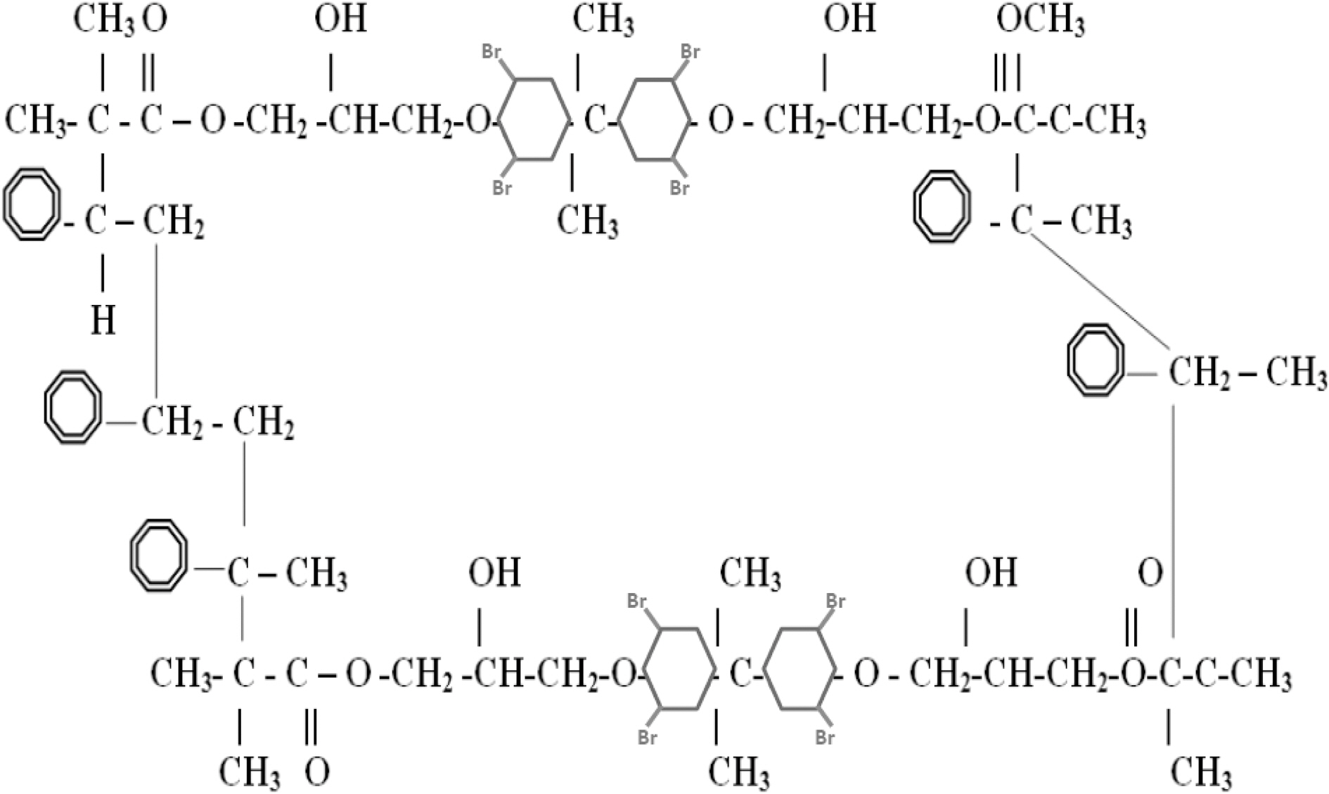
One of the key interactions between the nanoparticles and the matrix, for the ex-situ fabricated composites, is van der Waals force. However, the in-situ synthesis methods may create stronger chemical bonding within the composite. Introducing good interfacial bonding between nanofillers and the resin is often used to alleviate volume shrinkage, void formation and improve surface dispersion along with toughness. Control of interfacial adhesion appears to be crucial since a major cause of impact-related problems is believed to be associated with the level of adhesion at the interface between fiber and matrix. A variety of fiber surface treatment and modification techniques are used to control the interfacial bonding. The strong interface favors a brittle fracture mode with relatively low energy absorption; whereas, a weak interface favors a multiple shear mode with high energy absorption. Therefore, optimization of the interfacial adhesion is required to obtain excellent interfacial strength along with enhanced impact properties [16]. According to Gou, et al. [18], molecular dynamic simulations can provide detailed information on interface structure and interaction. The vinylester bromination effect is simulated to study the effect of bromination on the interfacial strength of vinylester-graphene and vinylester-graphite nanocomposites. High interfacial strength will result high stiffness, strength,and toughness in the composite [18,19]. Fig. 3 shows a schematic chemical chain for a brominated vinylester.
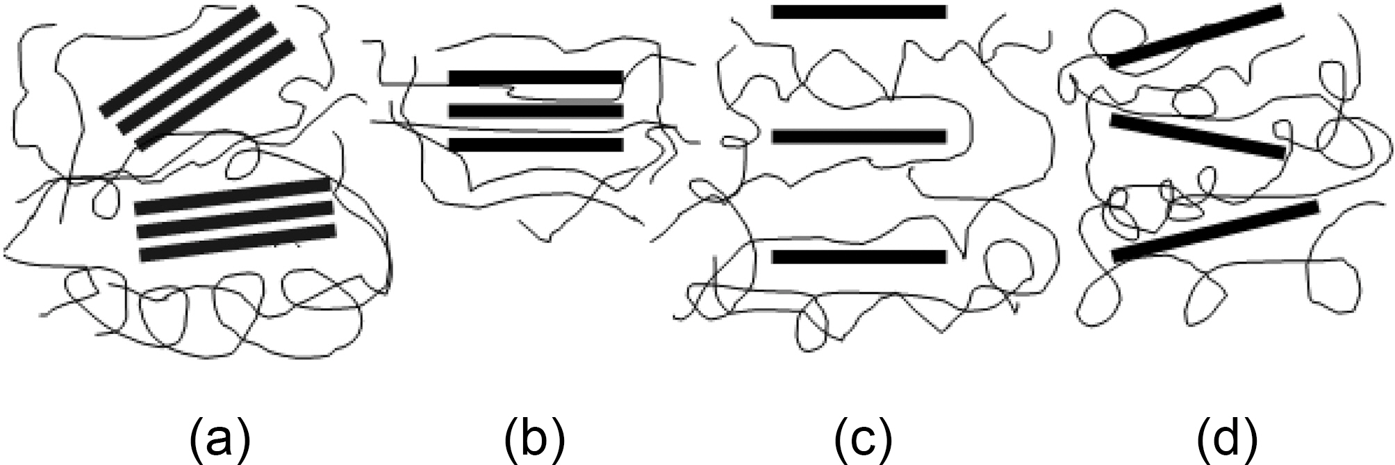
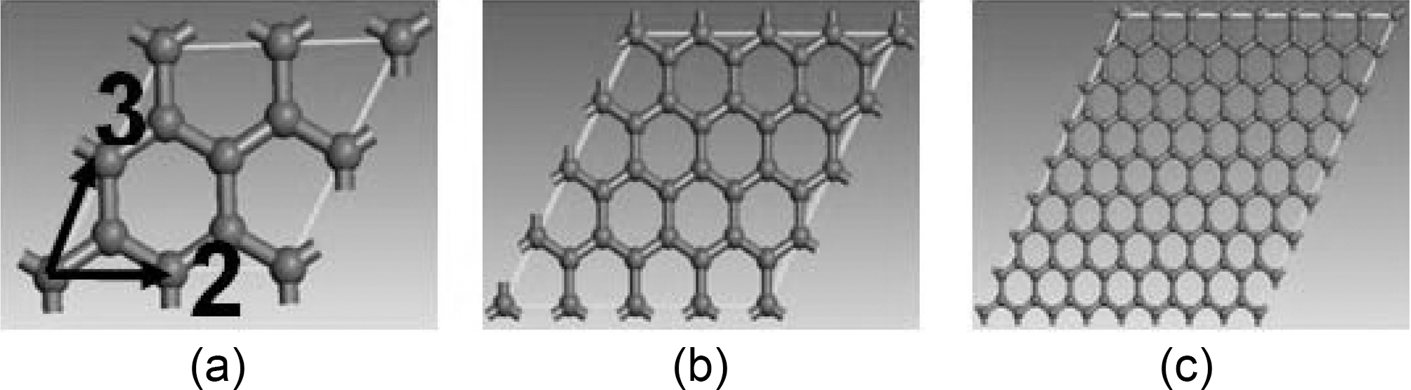
In general nano-platelet composites are classified into four types: conventional composite, intercalated composite, long range ordering composite (LRO), and disordered composite (Fig. 4). In a conventional composite (Fig. 4a), clay or graphite exists as a layered material with layers held together by van der Waals forces without any intercalation or exfoliation. In an intercalated composite (Fig. 4b), polymer chains are introduced into the graphite galleries, but the graphite still retains its layered structure. The distance between layers is in the range of 10~30 A. The size of the layered graphite extends from several hundred nanometers (nm) to several microns. Exfoliated composites have both exfoliated and dispersed graphite platelets with 1 nm thicknesses and several hundred-nm widths. This type can be divided into two groups, long-range ordered (LRO) (Fig. 4c)
and disordered composites (Fig. 4d). LRO composites have intercalated separated graphite platelets within (30~105 A) so that the adjacent platelets do not interact with each other. This configuration allows a comparable reinforcing effect for disordered composites. The key reasoning behind making platelet nanocomposites are intercalation of polymers inside the galleries and exfoliation of platelets in the matrix. Exfoliation leads to the improvement of bulk reinforcement by increasing its mechanical properties and aspect ratio
In order to understand nanocomposites; atomic structures; interfacial interaction between different matrices; and nanoreinforcements; atomic level interactions should be studied in details. Mechanical properties of nanocomposites could be predicted by realistic computational techniques that vary in time and length scales [20-22]. Molecular dynamics (MD) simulations can provide the structure, and the dynamic intercalated molecule details. MD is used to model nano layered graphite polymeric nanocomposites and their constituents elastic properties. After performing MD simulation, the resulting deformed molecular structure is analyzed to determine the elastic constants. Following the initial stage, three tensile and three pure shear strains with magnitudes of ±0.0005 are applied to the energy minimized system, with the system re-minimized following each deformation [23].
In the work presented in this paper, molecular interactions are described by Condensed-phase Optimized Molecular Potentials for Atomistic Simulation Studies (COMPASS) forcefield. COMPASS force field accounts for two function categories, valence terms including the diagonal and offdiagonal cross coupling terms, and nonbond interaction terms. The valence terms represent internal coordinates of bond, angle, torsion angle, and out-of-plane angle. The cross coupling terms include two or three internal coordinates potentials. The nonbond interaction terms include van der Waals for the Lennard-Jones function, and a Coulombic function for electrostatic interactions [23,24]. The MD simulations are performed using commercial software, Material Studio 4.1[23].
2. Simulation of Graphene Platelet Composites Using Molecular Dynamics
2.1. Simulations of graphene/graphite
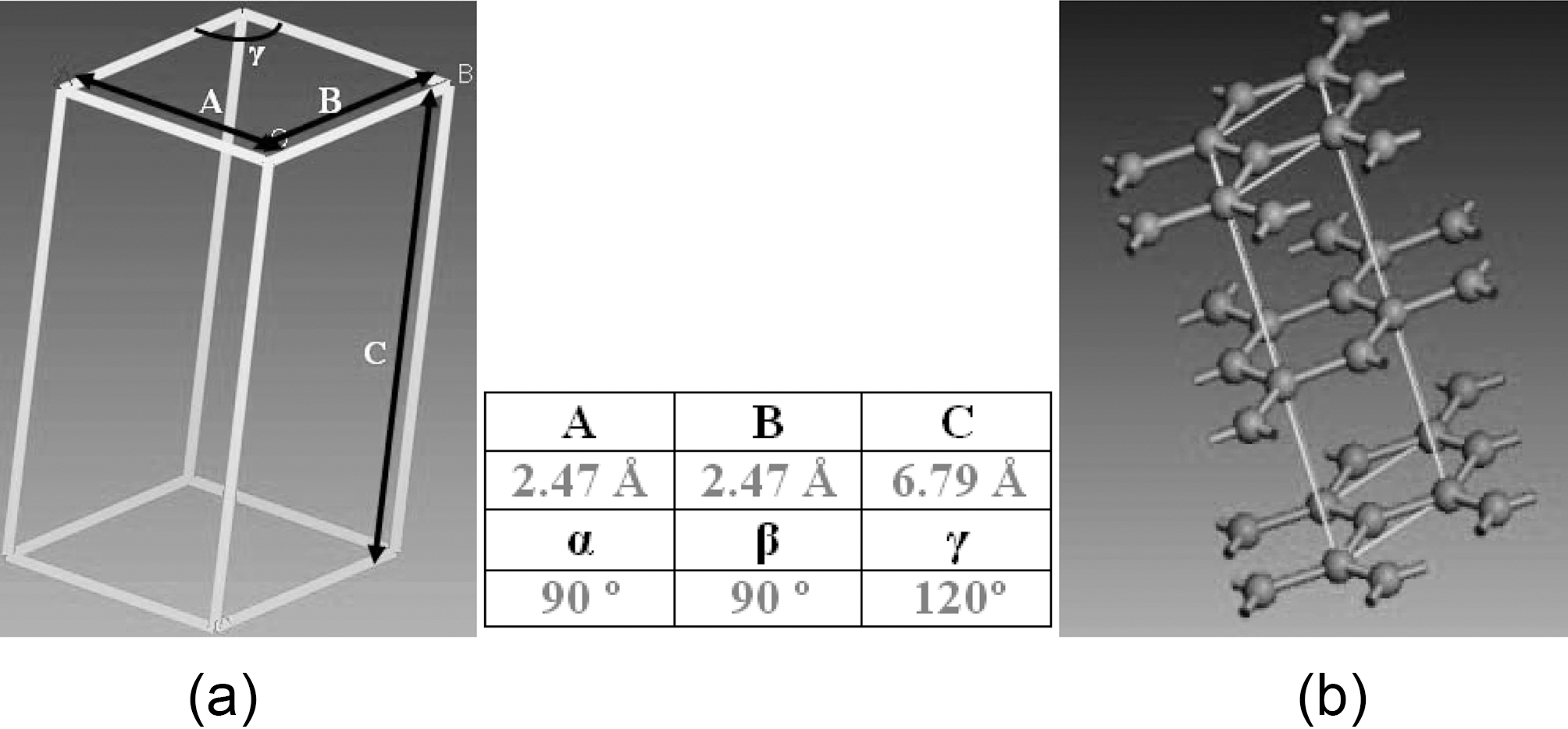
Graphite atomic hexagonal crystal group 186 P63MC is constructed with dimensions shown in Fig. 5. Molecular dynamic geometry parameters, such as periodic cell size and number of layers, are simulated to study their effect on graphene mechanical properties. NVT, which stands for constant number of atoms, constant volume, and constant temperature, associated with Anderson thermostat is the thermodynamic ensemble applied through the entire simulated configurations.
A structure energy minimization followed by a dynamic system equilibration under NVT ensemble is applied for predetermined dynamic time. Dynamic time for simulated atomic structures is proportional to the number of atoms included in each supercell. A dynamic step of 0.1 fs, and a 100 kcal/mol energy deviation are kept constant for all graphene conducted simulations.
2.2. Simulations of polymeric matrices (vinylester, brominated vinylester)
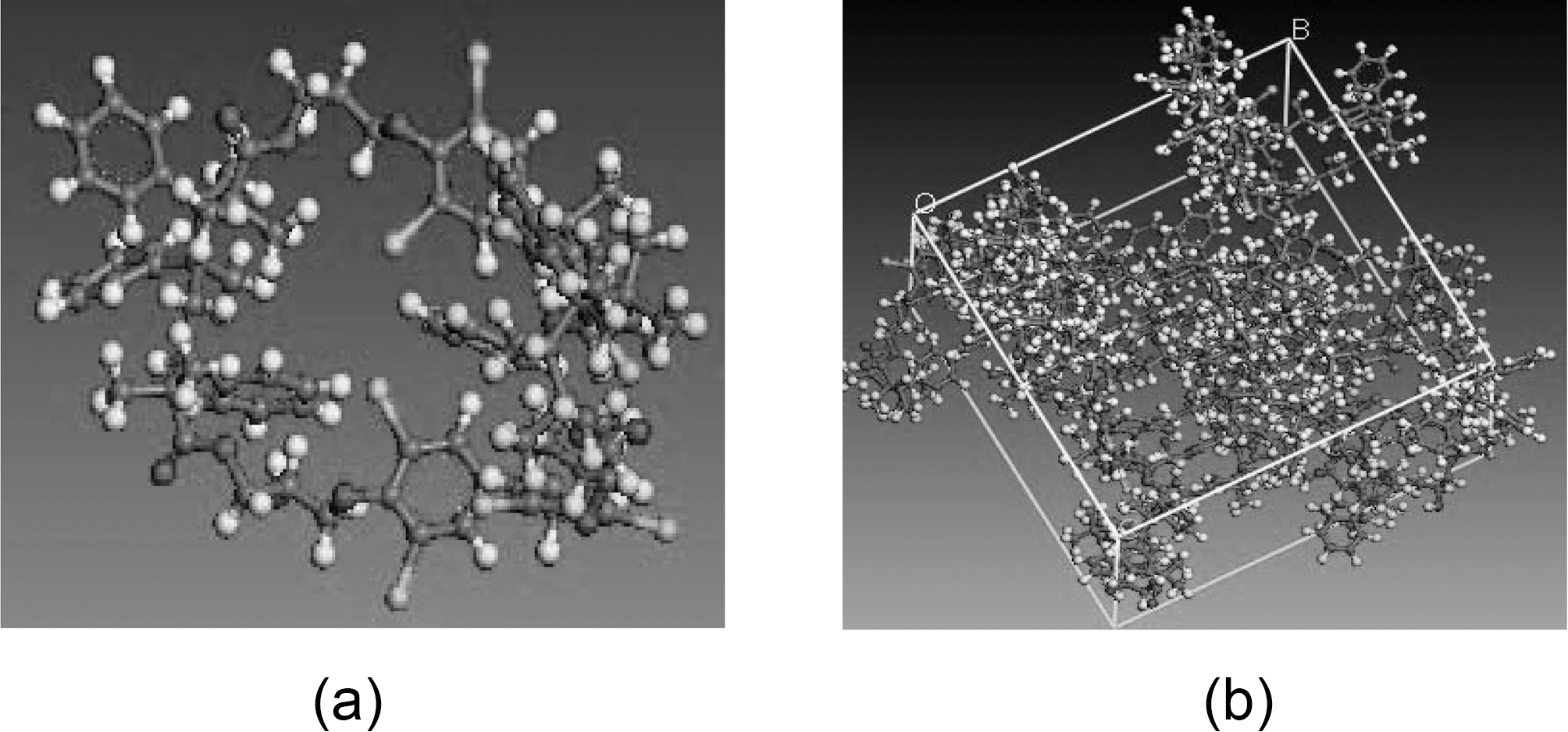
An amorphous cell molecular dynamics module is recommended for amorphous polymers to optimize their
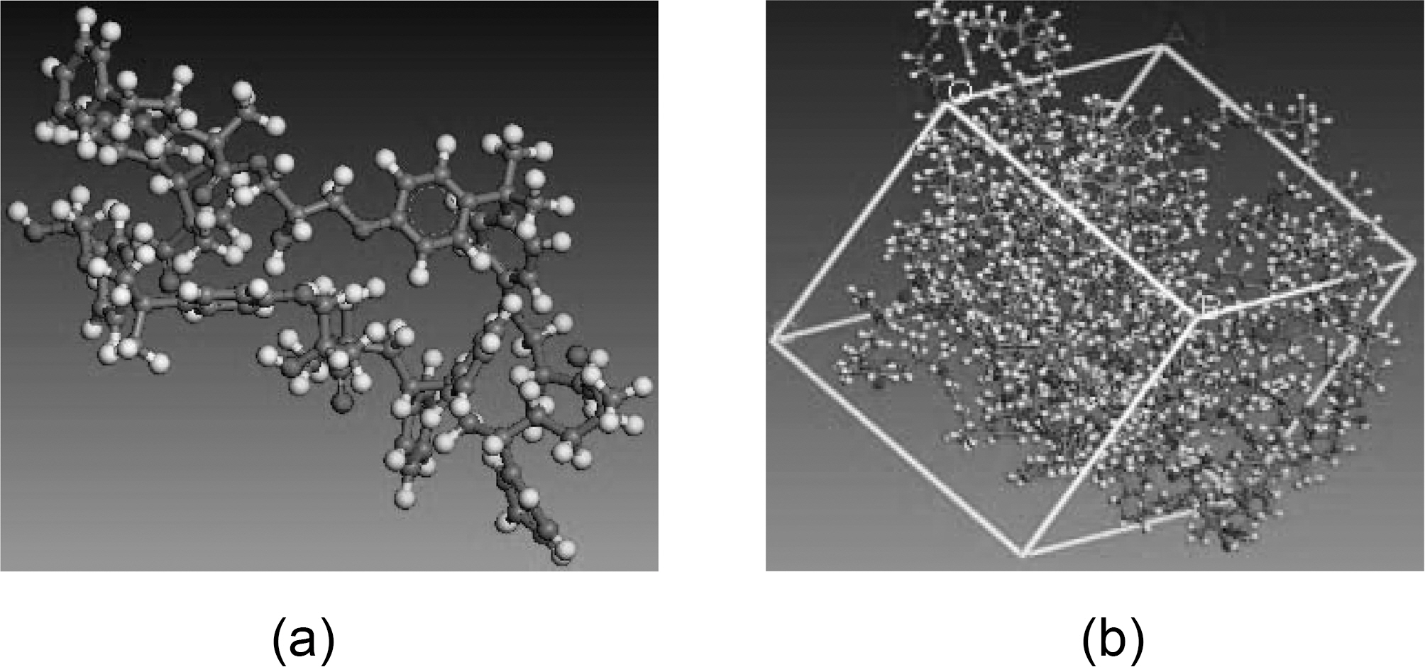
mechanical behavior, surface characteristics, and interface interactions. An Amorphous module is a suite of computational tools that allow assembly of representative models of complex amorphous system that anticipate the key properties. Simulation parameters which are required to setup the simulation include: system composition chemical chain, temperature, and density. Representative volume element (RVE) models are established from equilibrated vinylester/brominated vinylester atomic structures governed by COMPASS forcefield. The RVE is constructed of ten atomic vinylester/brominated vinylester chains each of 230 atoms. Vinylester simulation parameters are bulk periodic cell density 1.04 g/cm3 at room temperature 298 K, and Tg =400 K, Fig. 6. Brominated vinylester simulation parameters are bulk periodic cell density 1.53 gm/cm3 at room temperature 298 K, and Tg = 400 K, Fig. 7. Bromination of vinyl ester will increase the density due to the replacement of some of the hydrogen atoms. There are four bromine (Br) atoms replacing four hydrogen (H) atoms. Br has a large atom weight (79.904 g/mol) compared to H (1 g/mol). Considering chemical chain structure shown in Fig. 2 and 3, the calculated molecular weight of the regular vinyl ester is 1190, while that of the brominated vinyl ester is 1822.Assuming that the unit cell volume is about the same, the density will increase by about 53%.
RVE molecular systems are condensed with NPT (constant number of atoms, pressure, and temperature, MD simulations at 300 K and 1 atm for 50 ps. This process is followed by NVT (constant number of atoms, volume, and temperature for 100 ps raising the molecular system temperature from 300 K to 400 K in stepwise dynamic simulation. For each polymeric system temperature, this is followed by an NPT dynamic step-wise temperature reduction back to room temperature 300 K. Static mechanical properties are calculated for each equilibrated cell.
2.3. Simulations of graphene-vinylester and graphenebrominated vinylester interfacial properties
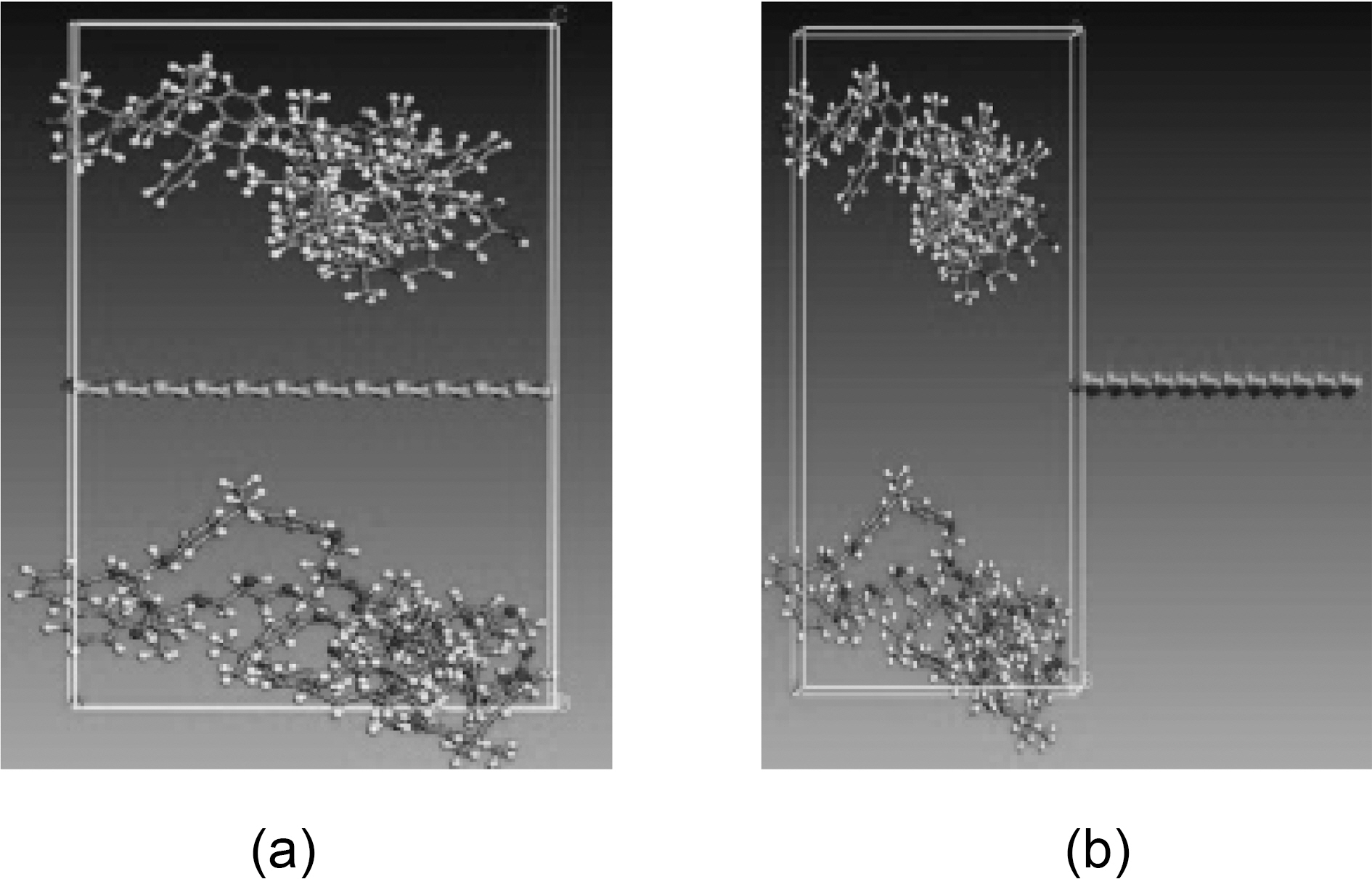
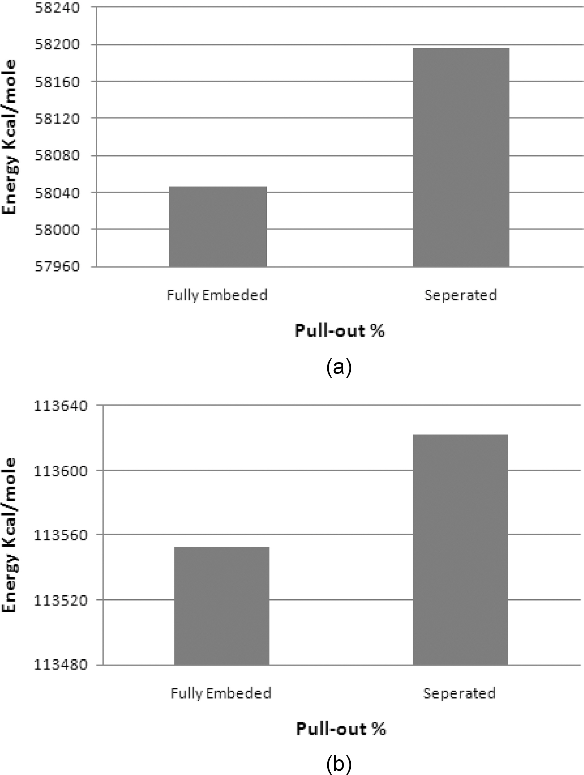
The pullout energy, Epull-out, is defined as the energy difference between the fully embedded graphene plate and the complete pull-out configuration. It can be related to the interfacial shear stress, τi, by the following:
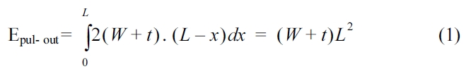
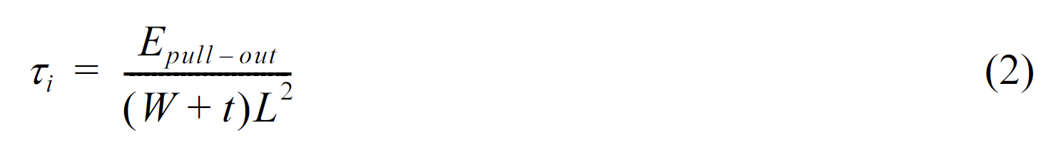
where, W, L and t are the width, length, and thickness of the
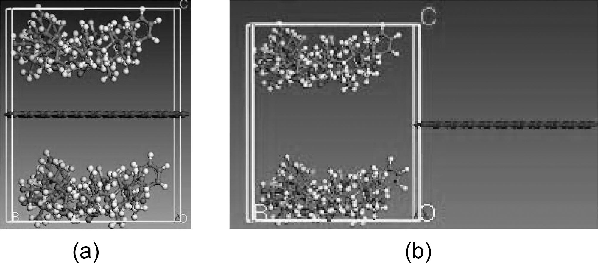
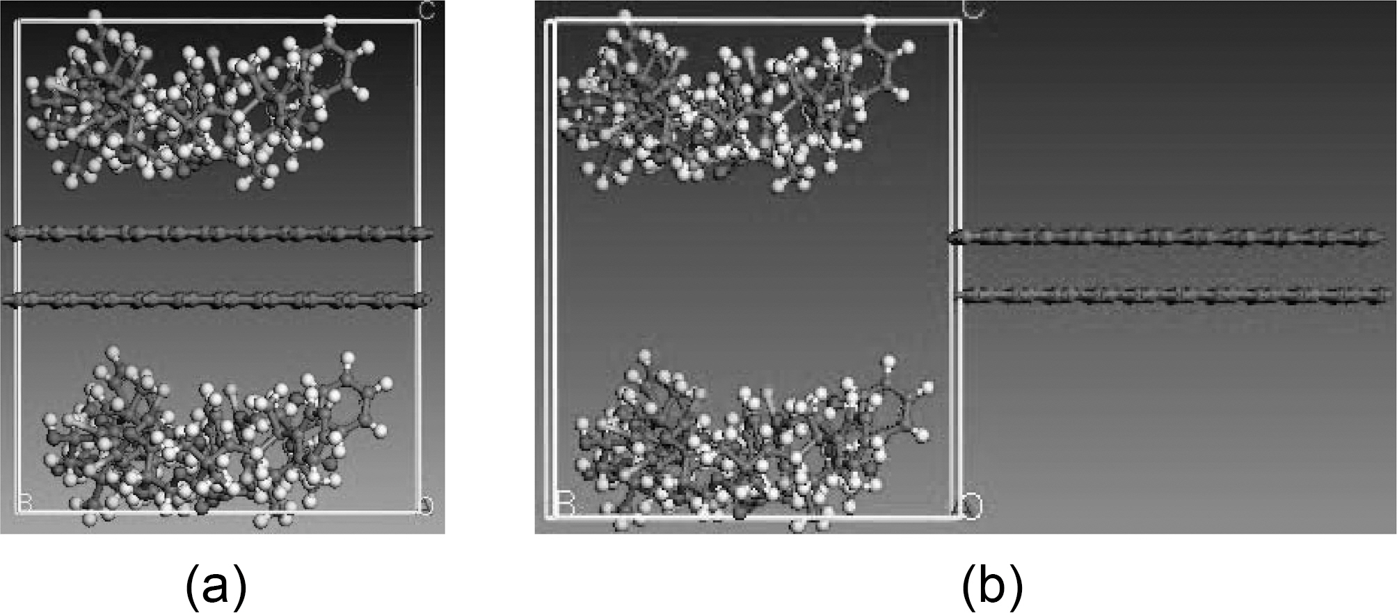
graphene plate, respectively, and x is the displacement of the graphene sheet. Molecular dynamics simulations are carried out for the following fiber-polymer pull-out energies: 1. graphene-vinylester interface (Fig. 8), 2. graphite-vinylester interface (Fig. 9), 3. graphene-brominated vinylester interface (Fig. 10), and 4. graphite-brominated vinylester interface (Fig. 11).
2.4. Simulations of graphene composites
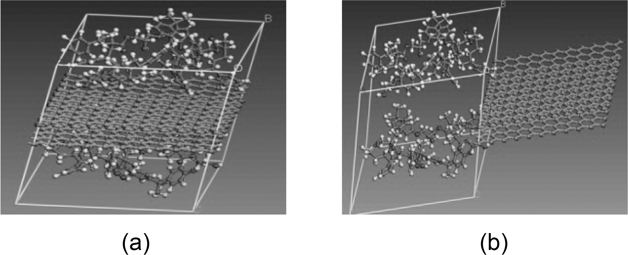
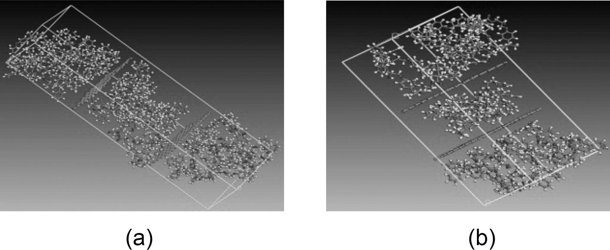
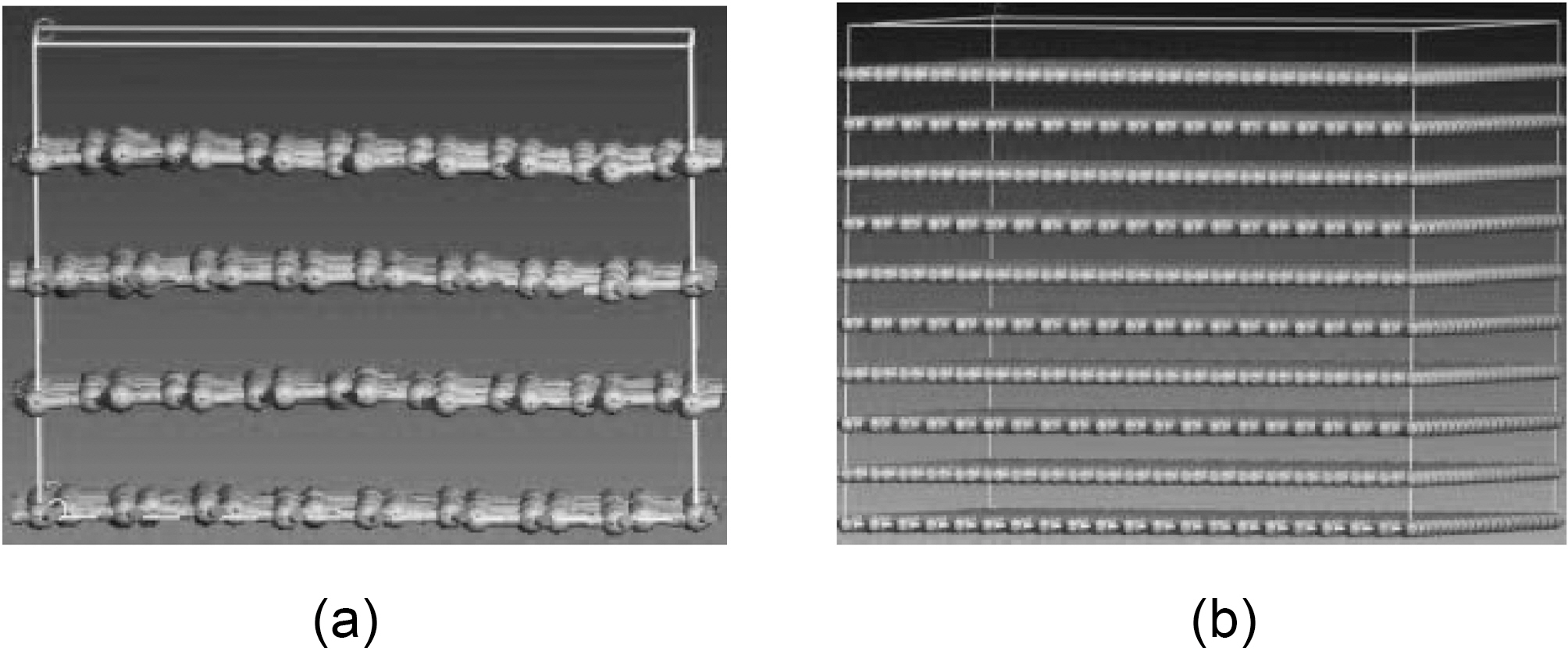
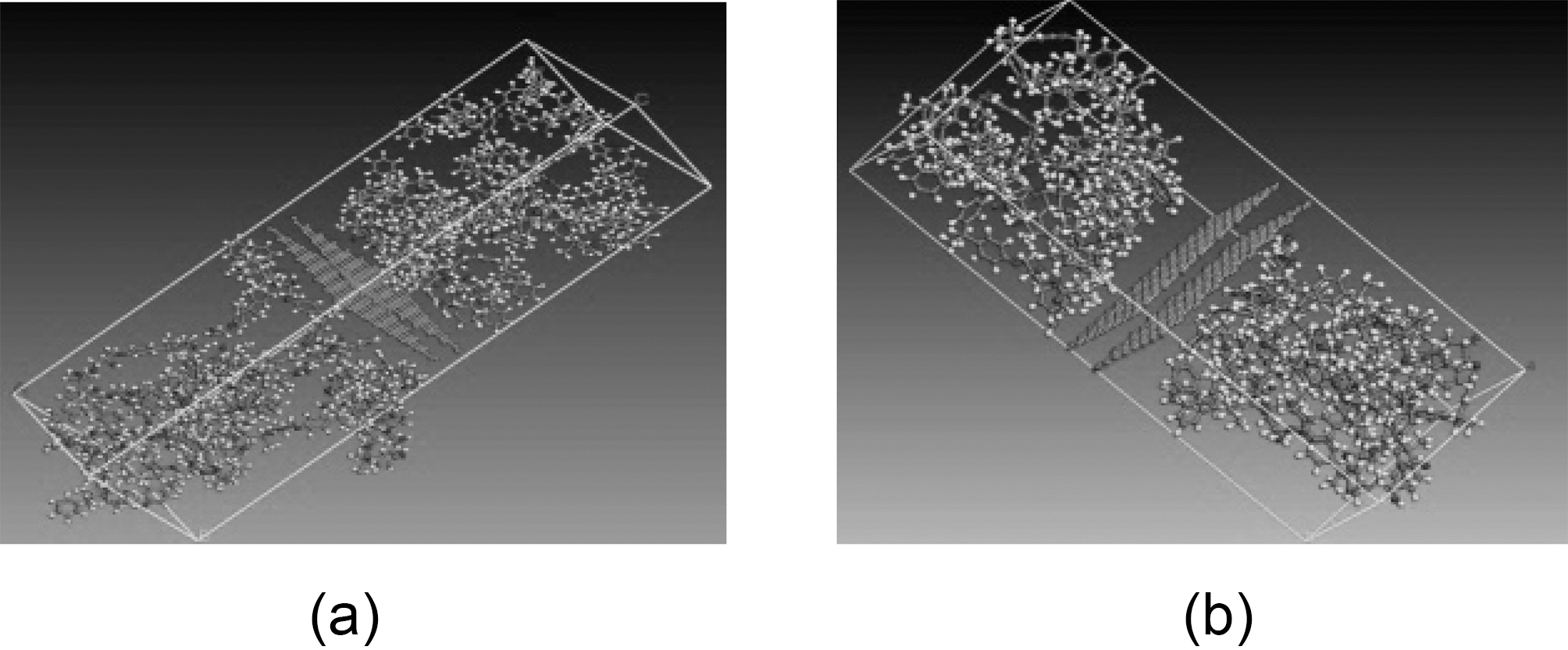
Simulations are carried out for 10 and 20% of graphite-vinylester (Fig. 12a and b), and for exfoliated graphene-vinylester composites (Fig. 13a and b). The simulation conditions and cell sizes that have been constructed are mentioned later in Table VIII. The NVT and NPT step simulations described earlier in matrix molecular modeling are
applied to the composite simulations. Hence, the temperature of the system is maintained at 298 K throughout the simulation.
3.1. Mechanical properties of graphene
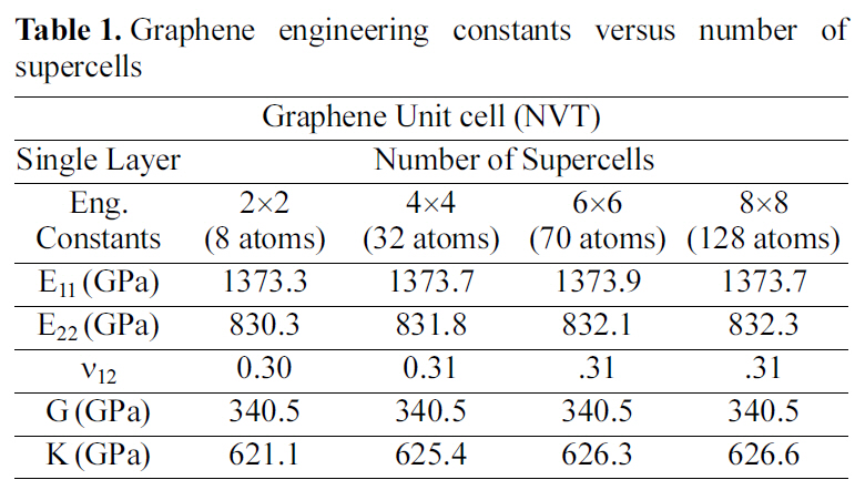
Graphene supercells of different sizes are shown in Fig.14. Elastic constants of the numerous super cells are shown in Table 1. Where E, G, K are the Young’s, shear, bulk moduli respectively, and ν is the Poisson’s ratio. The periodic cell size for the graphene is a 2 ×2 supercell crystal.
3.2. Mechanical properties of graphite
3.2.1. Effect of unit cell size
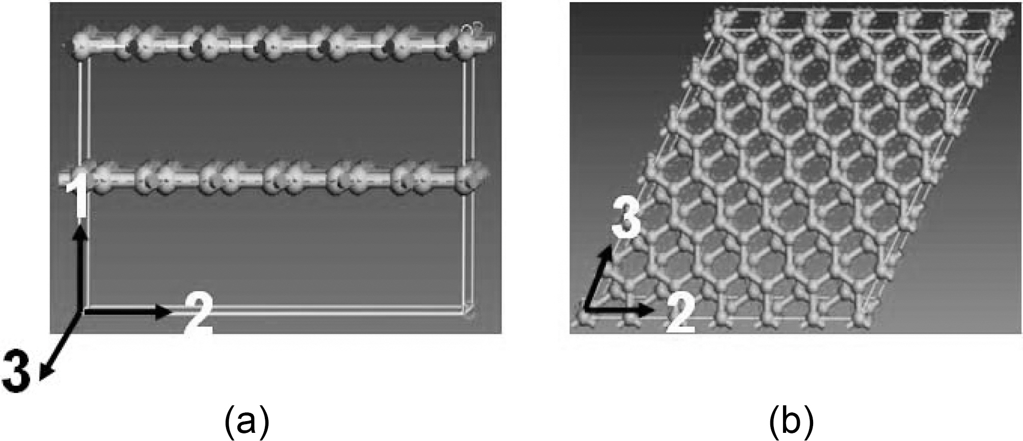
Fig. 15 shows a double layered graphite molecular
[Table 1.] Graphene engineering constants versus number of supercells

Graphene engineering constants versus number of supercells
[Table 2.] Double layer graphite engineering constants versus number of supercells
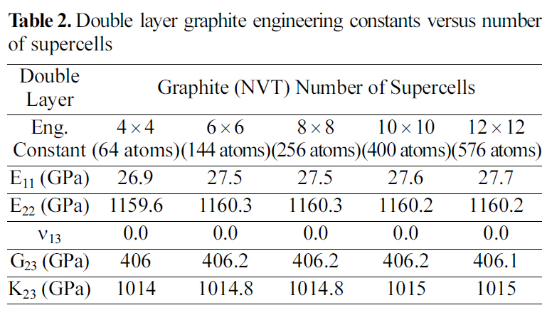
Double layer graphite engineering constants versus number of supercells
[Table 3.] Four layer graphite engineering constants versus number of supercells
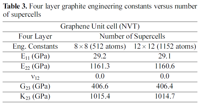
Four layer graphite engineering constants versus number of supercells
supercell, side and top views. Several graphite supercells are simulated to study the effect of the supercell size on graphite mechanical properties and to obtain the periodic cell dimensions for the graphite atomic structure.
Table 2 and 3 show the engineering constants for the graphite molecular structure of different supercell sizes. From Table 2 and 3 it can be seen that the engineering constants tend to remain steady for both supercell structures at 4×4 size for the double layer, and at 8×8 for the four layered graphite. Increasing the number of layers simulated requires a larger supercell to represent the periodic simulated graphite cell.
3.2.2. Effect of Number of Layers
Several layers are simulated to study their geometrical effect on graphite mechanical properties. Fig. 16 shows a
[Table 4.] Periodic graphite cells engineering constants versus number of layers
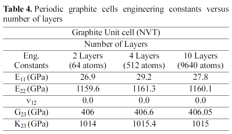
Periodic graphite cells engineering constants versus number of layers
[Table 5.] Vinylester engineering constants versus number of chains
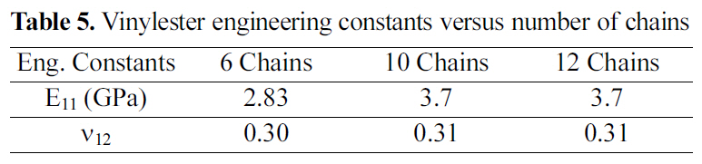
Vinylester engineering constants versus number of chains
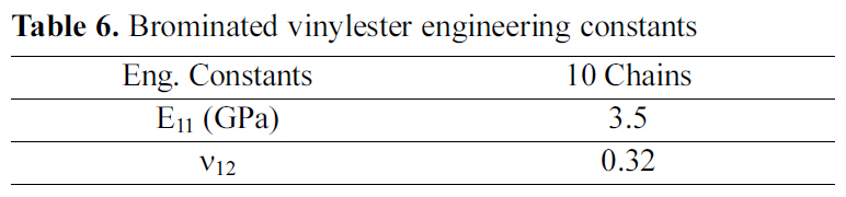
[Table 6.] Brominated vinylester engineering constants

Brominated vinylester engineering constants
molecular crystal structure for a four-layered and a ten-layered graphite supercell. Table 4 demonstrates the engineering constants for double, four, and ten layered graphite periodic cells. The results recorded in Table 4, affirm that the variation of the engineering constants for the multi layered graphite periodic cells is less than 5%.
3.3. Mechanical properties of vinylester
Table 5 shows the engineering constants of a vinylester amorphous cell for 6, 10, and 12 chains. From results shown,an amorphous cell of 10 chains of vinylester and 3200 total atoms is the periodic cell of such a polymeric structure. Hence, increasing the amorphous cell atomic size and simulated number of atoms will not induce any mechanical property variation or improvement beyond the 2300 atom periodic cell.
3.4. Mechanical properties of brominated vinylester
Table 6 demonstrates the engineering constants for brominated vinylester amorphous cell, of 10 chains. The results indicate as expected that the bromination of vinylester did not vastly affect the mechanical properties.
Comparing the MD results shown in Table 5 and 6, the calculated elastic modulus of vinylester is higher than that of brominated vinylester. This result does not match observed experimental values where bromination is expected to increase stiffness of vinylester. However, in these simulations an ideal vinylester chain, that does not include unreacted epoxy, was used. The presence of unsaturated vinylester reduces the mechanical properties. Different amount of unreacted epoxy molecules may exist for cases of brominated and unbrominated vinylester. This paper, indirectly, suggests that bromination could reduce the amount unreacted epoxy molecules in vinylester.
3.5. Interfacial strength (graphene/graphite-vinylester/brominated vinylester)
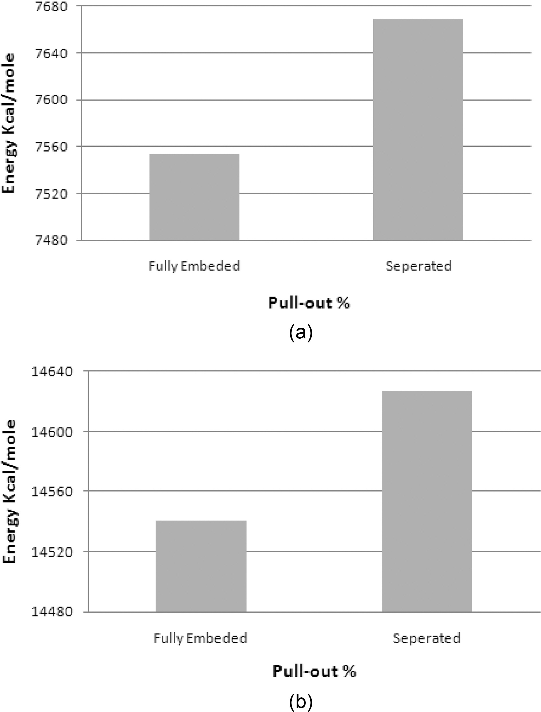
The Epull-out calculated from MD simulation for the vinylester-graphene is 149.61 kcal/mol. The energy plot is
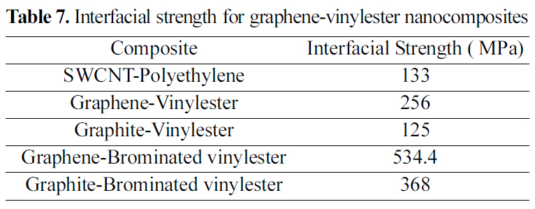
[Table 7.] Interfacial strength for graphene-vinylester nanocomposites

Interfacial strength for graphene-vinylester nanocomposites
shown in Fig. 17(a). The properties of the unit cell simulated for the pull-out energy are: density of 0.37 g/cm3, molecular weight of 10672 gm/mol, and cell dimensions of (L=29.64 A, W=29.64 A , t=3.4 A) Fig. 8. According to equations (1-2), the interfacial strength is calculated to be τi= 256 MPa, which is double the calculated interfacial strength value for the SWCNT- Polyethylene reported in [18,25].
A similar atomic cell structure is constructed for the graphite (Fig. 9) to study the interfacial strength of a multi layered graphene nanoplatelet. Double layered graphite is chosen with a density of 0.572 g/cm3, molecular weight of 13104 g/mol, and cell dimensions of (L=29.64 A, W=29.64 A ,t=3.4 A). Epull-out for the double layer of graphite is 69.8 kcal/mole Fig. 17(b). The interfacial strength calculated from
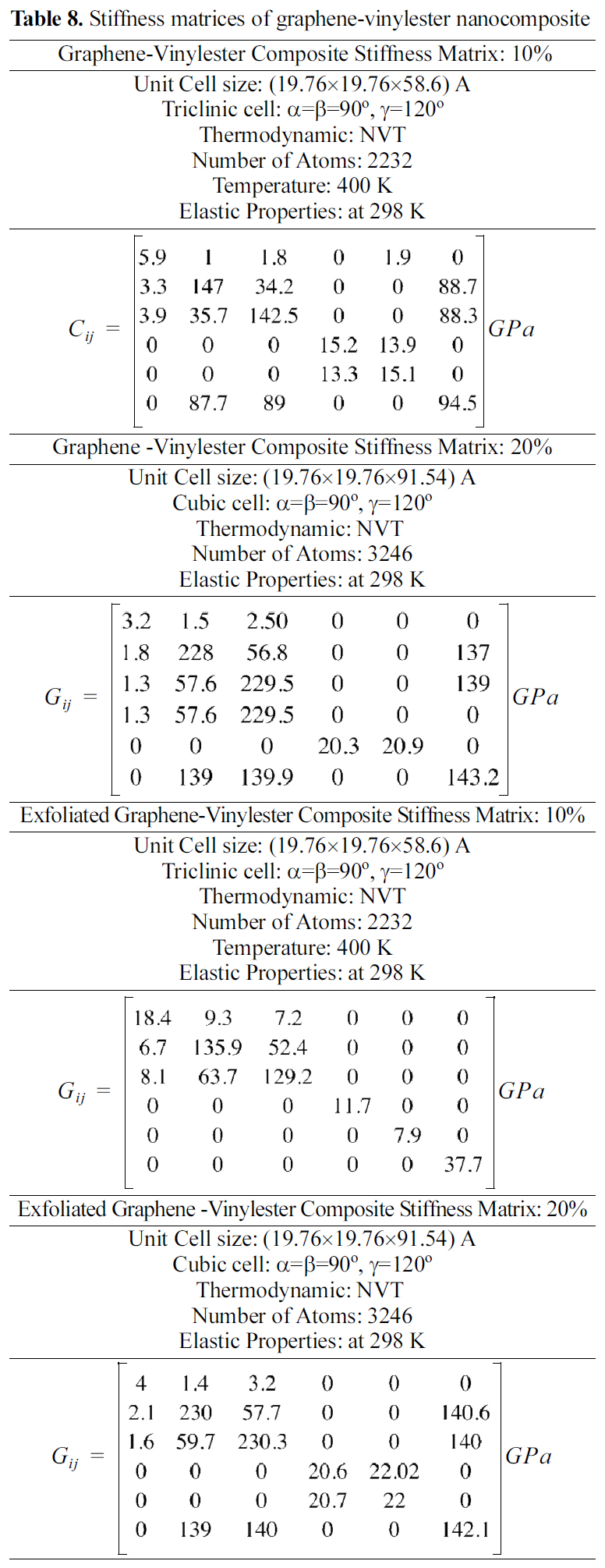
[Table 8.] Stiffness matrices of graphene-vinylester nanocomposite

Stiffness matrices of graphene-vinylester nanocomposite
equations (1-2) is 125 MPa, which is less than half of the graphene interfacial strength.
Vinylester bromination effect on interfacial strength of vinylester bromination- graphene/graphite is simulated in this study. Although the mechanical properties of the brominated vinylester are comparably close to vinylester, a great interfacial strength enhancement is shown in the simulated pull-out energy configurations. Potential energy variation plots for a pull-out simulation for (a) graphenebrominated vinylester and (b) graphite-brominated vinylester are shown in Fig. 18 Interfacial strengths summary is shown in Table 7.
3.6. Molecular dynamic simulations of vinylester nanocomposites
Stiffness matrices for 10 and 20 wt.% reinforcements are shown in Table 8. Results shown in Table 8 demonstrate that exfoliated graphene platelets nanocomposites have higher elastic properties than the graphite nanocomposites.
This paper demonstrates the viability of using molecular dynamics simulations to estimate mechanical properties of graphite-vinylester composites and their constituents (matrix, reinforcement and interface). Engineering constants for vinylester matrix (brominated and unbrominated), reinforcement (graphene and graphite), and composites were theoretically calculated. Interfacial shear strength at vinylester-graphene/or graphite was estimated.