Recently, clays have drawn great interest both in academia and industry, because they often exhibit remarkable improvement in materials properties when used as filler for composite materials [1]. Most of the researches are focused on clay/polymer nanocomposites, even though there is another type of important composite materials, carbon fiberreinforced carbon composites (C/C composites).
Carbon fiber-reinforced carbon (C/C) composites are promising candidates for the applications for extreme environment, such as brake discs for advanced aircrafts, heat shields of reentry vehicles, nozzles of solid rocket motors, and aerospace applications for nose tips and leading edges [2,3]. And it was resulted from outstanding properties of C/C composites,such as high strength-to-weight ratio, low density, excellent thermal stability, high thermal conductivity, low coefficient of thermal expansion, and resistance to thermal shock and ablation [4-6]. However, the applications of the C/C composites are limited by their oxidation at temperatures above 450℃ [7]. Therefore, for the wide range of applications, it is required to improve oxidation stability of C/C composites.
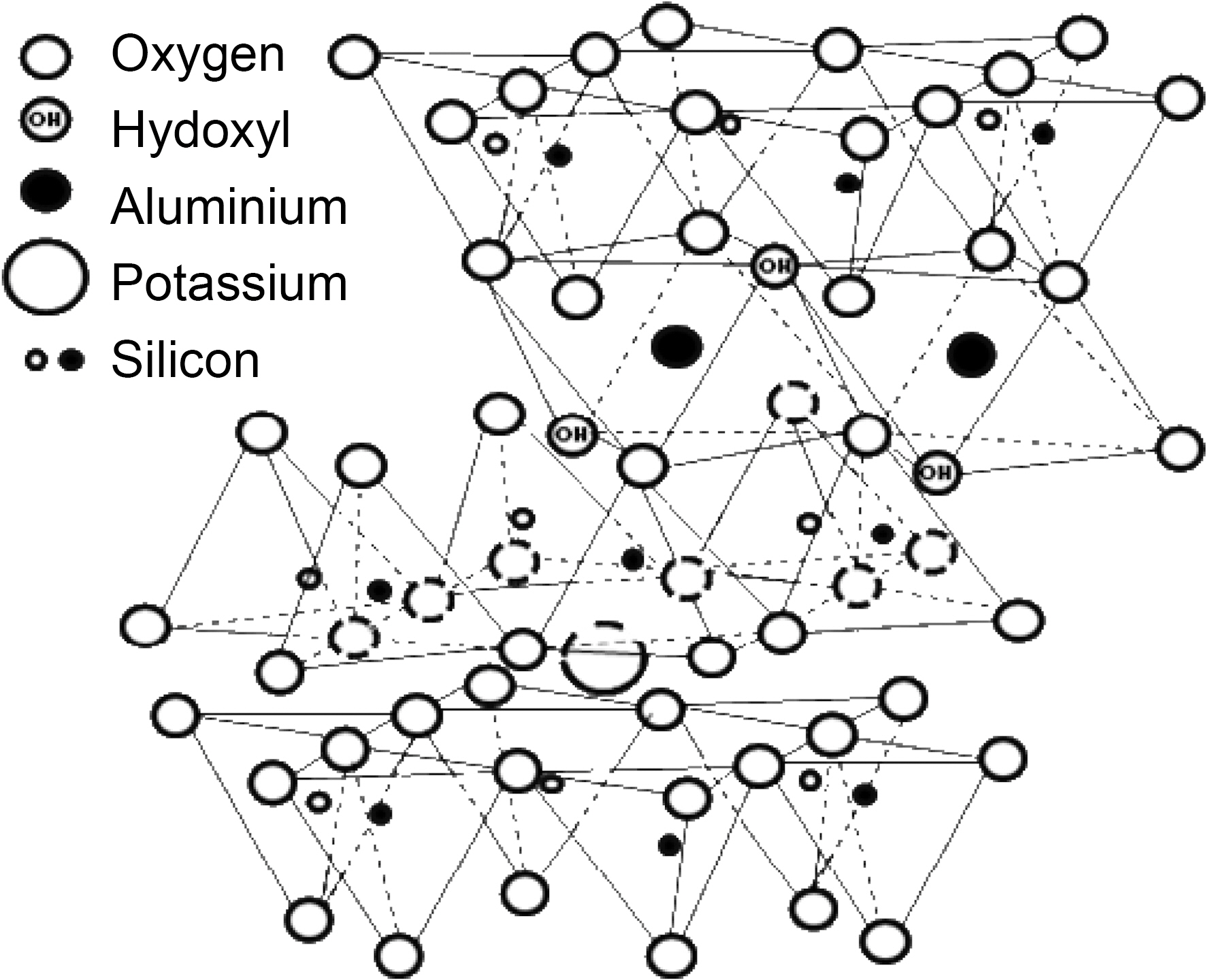
There are two general methods reported to improve the oxidation stability of C/C composites, coating carbon fiber or the C/C composite with an anti-oxidizing layer and adding antioxidizing fillers directly into the matrix [8]. Anti-oxidizing fillers, such as SiC, SiO2, MoSi2, ZrB2, SiB4, and Si3N4, have been used due to the ease of the process [9,10]. However, adverse effects of these fillers on the human body were found [10]. In this regard, it is worth to consider use of clay filler for C/C composites. Illite is one of the most abundant clay materials on earth and a promising candidate as clay filler. The chemical structure of illite is shown in Fig. 1. Pure illite contains SiO2 and Al2O3 as main components and raw illite contains quartz whose main component is SiO2 as impurities [11]. It is generally known that those are the fillers to provide good thermal properties [12]. In addition, it is possible to form SiC when illite is used as filler during the carbonization of phenol resin, resulting in additional improvement in oxidation stability of C/C composites. And it was actually proved by the authors’ previous work [13]. On the other hand, illite has layered structure which is reported to have a lubricant effect to enhance impregnation or infiltration of liquid-type materials, such as Si liquid slurry, polymer or pitch melt [14] and this enhancement is also expected to improve oxidation stability or mechanical properties of the C/C composites.
When ceramic filler, such as clays, is used for composites,it was found that size reduction of ceramic particles increased dispersion in solvent or polymer and improved materials properties of the composites [15]. Therefore, size reduction of illite is expected to improve the illite dispersion in phenol resin, possibly enhance infiltration of illite into
carbon perform, and improve materials properties.
Therefore, in this study, to investigate new potential application of a clay material for C/C composites, illite added C/C composites were prepared with various illite contents. Improvement of filler effect by illite size reduction was also investigated using wet ball milling by evaluating illite/phenol resin infiltration using bulk density and porosity measurement, chemical structural changes of the composites using XRD, and thermal oxidation stability in air of the composites using TGA.
Illite (1000 mesh) was provided by Yonggoong illite Co., Korea. Needle-punched PAN-based carbon preform was manufactured with 12 K oxy-PAN fibers and provided by DACC Co. Ltd., Korea. Resol-type phenolic resin (HM2) was provided by Kolon Chemical Co., Korea.
Size reduction of illite was carried out using a wet ball-milling apparatus, a paint-shaker and the details about the apparatus was already introduced in the other research [15]. 100 g of illite, 100 g of methanol, and 200 g of zirconia balls were mixed and shaken for 0, 1, and 2 h. The zirconia balls were separated by filtration and the resultant filtrate was used without any further treatment for the preparation of C/C composites.
Illite-C/C composites were prepared in the following manner. Illite was added to phenol resin at 1, 3, 5, and 10 wt% of phenolic resin-base and stirred for 2 h. Then, a needle-punched carbon preform was impregnated with the illite/phenolic resin mixture at 0.2 bars for 10 min. The impregnated preform was dried in a thermo-reactor at 70℃ for 3 h. The phenolic resin impregnated into carbon preform was cured at 130℃ for 5 h. Then, the phenolic resin/carbon composite was carbonized at 1650℃ for 1 h under Ar gas.
2.4. Charaterization of raw and physically modified illite and C/C composites
A scanning electron microscope (JEOL Co., JSM 700F) and a laser scattering particle size analyzer (Sympatech GmbH Co., HELOS/RODOS) were used to investigate effect of size reduction on illite particle size.
X-ray diffraction experiments (XRD, Rigaku International Corporation, D/MAX-2200 Ultima/PC, Japan) were carried out to investigate the chemical changes in the C/C composites, especially the formation of SiC, depending on the amount of illite added and compare illte infiltration into carbon preform with/without size reduction. Bulk densities and porosities of the prepared composites were evaluated using the ASTM C20 method.
Thermogravimetric analysis (TGA, Mettler-Toledo, TGA/SDTA851, Switzerland) was performed to evaluate thermal oxidation stability of the prepared samples at a heating rate of 5℃/min in air.
3.1. Results of illite size reduction
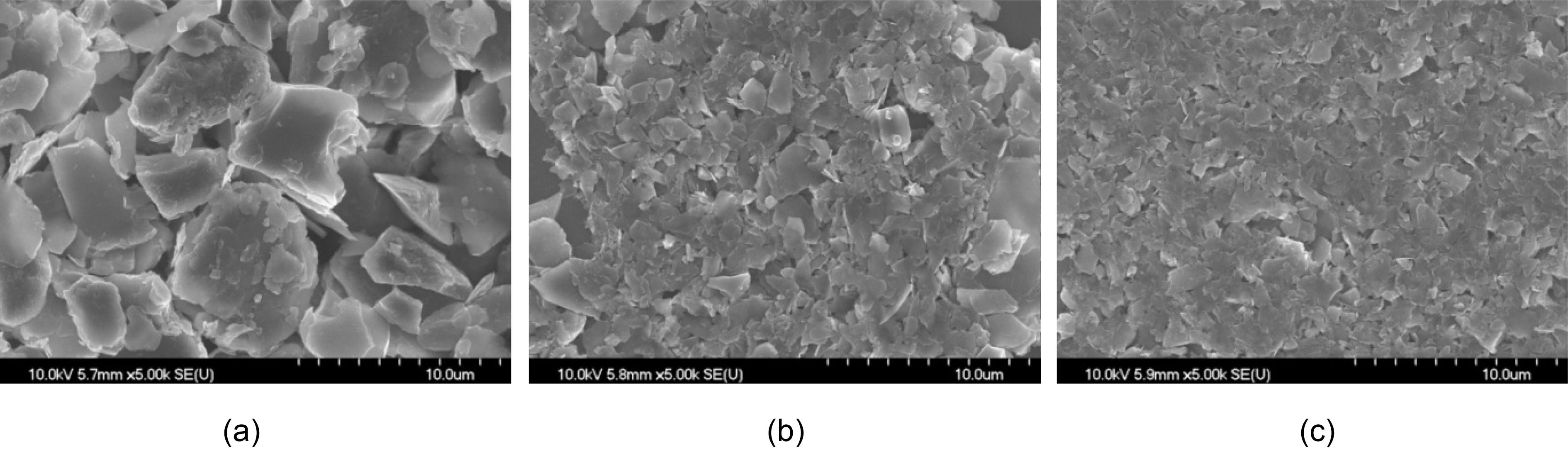
SEM images of the illites after size reduction with different treatment times are shown in Fig. 2. The particle sizes of 0 h treated (pristine) illite varied from 1 to 10 ㎛ in Fig. 2(a). In other words, the particle size distribution is wide and many big particles (about 10 ㎛ size) are observed. As the treatment time increases, the particle size distribution becomes narrower and big particles disappear as shown in Fig. 2(b) and 2(c).
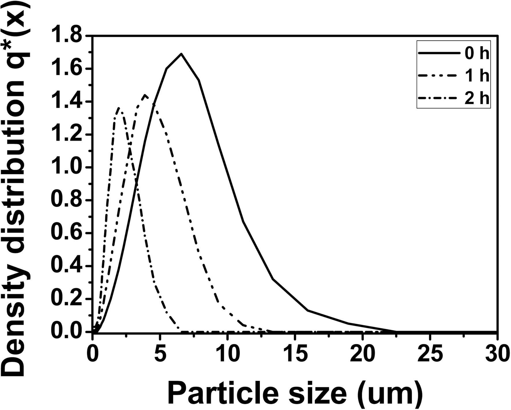
The quantitative analysis of the particle size distribution of the illites after physical modification with different treatment times is shown in Fig. 3. Pristine illite has the widest particle size distribution with X10 = 2.11 ㎛, X50 = 5.42 ㎛, and X90 =10.02 ㎛, showing 80% of the particles have 2.11~10.02 ㎛ size and the most dominant particle size is 5.42 ㎛. 1 h treated illite has the particle size distribution with X10 = 1.39 ㎛, X50= 3.82 ㎛, and X90 = 7.69 ㎛, showing 80% of the particles have 1.39~7.69 ㎛ size and the most dominant particle size is 3.82 ㎛. And 2 h treated illite has the particle size distribution with X10 = 0.84 ㎛, X50 = 2.10 ㎛, and X90 = 4.63 ㎛, showing 80% of the particles have 0.84 ~4.63 ㎛ size and the most dominant particle size is 2.10 ㎛. Therefore, particle size
distribution of illite was reduced after 2 h treatment by the factor of 0.5, compared to that of pristine illite. The particle size distribution of illite with more than 2 h size reduction did not exhibit any significant reduction in our preliminary experiment. Hence, those data were excluded in this study. It is also important to note that the needle-punched carbon preform used in this study has 5 ㎛ of yarn-yarn distance. Therefore, it is expected that the 2 h treated illite can be infiltrated into the carbon preform more and easier during the impregnation of illite/phenol resin mixture, compared to the non-treated illite. In that case, it is also expected that the C/C composites infiltrated with 2 h treated illite have more improved oxidation stability, compared to that of the C/C composites with 0 h treated illite. This will be further discussed in the later sections.
3.2. Effect of size reduction on SiC formation and illite/phenol resin infiltration
Since the particle distribution of the 2 h treated illite is the narrowest, only 2 h treated illite is used to prepare C/C composites as filler and chemical composition and oxidation
stability of the resultant composites are compared with that of 0 h illite-C/C composites from the previous study [14].
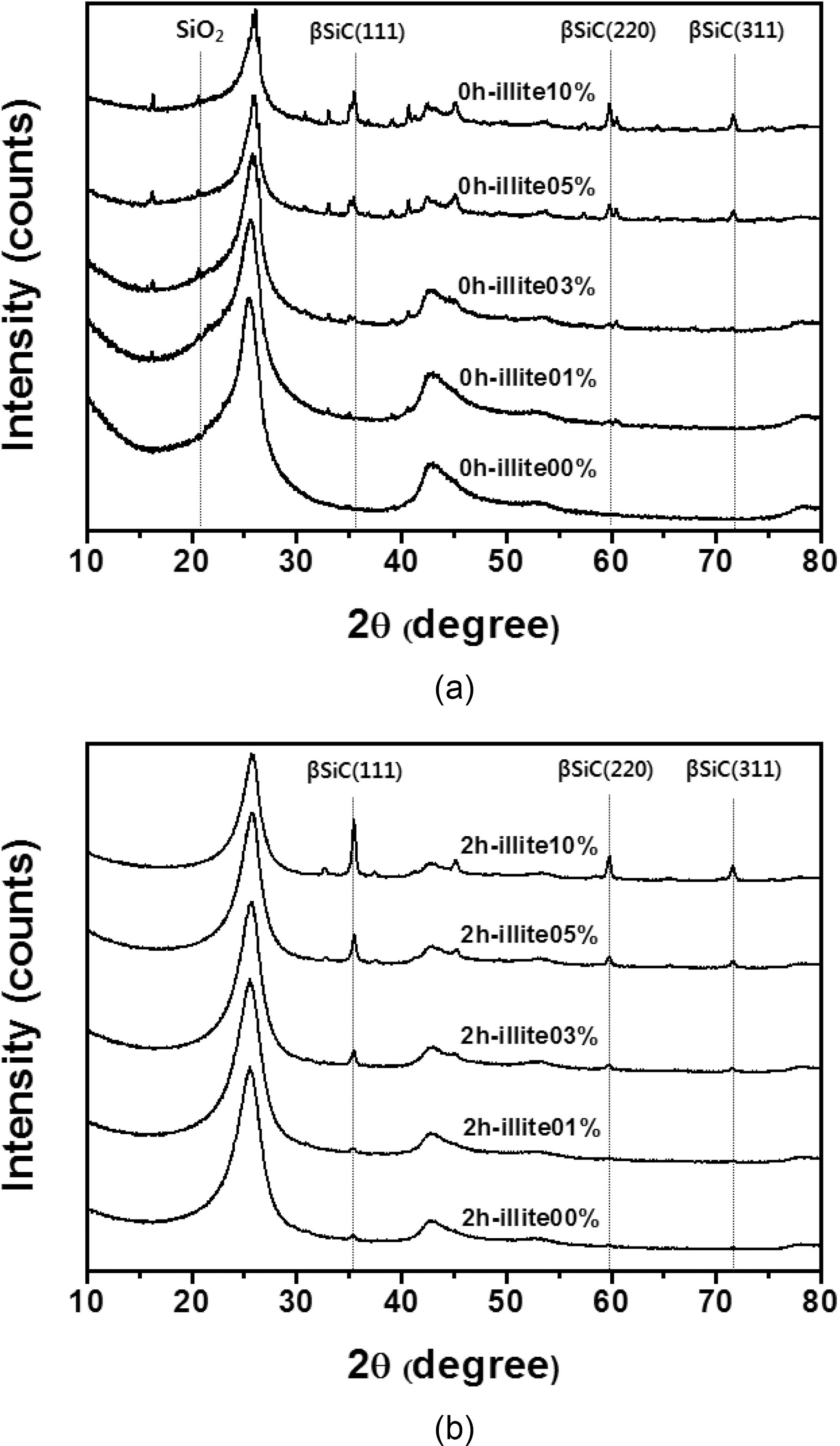
XRD patterns of the illite C/C composites are shown in
[Table 1.] Quantitative analysis of SiC in XRD patterns in Fig. 6
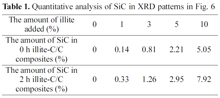
Quantitative analysis of SiC in XRD patterns in Fig. 6
Fig. 4. The new peaks, at 35.68, 60.06, and 71.80°, correspond to the (1 1 1), (2 2 0), and (3 1 1) peaks of β-SiC, respectively,and these peak positions are in good agreement with other studies [16-18]. The formation of β-SiC was expected because of the presence of SiO2 in illite, which could react to produce β-SiC during carbothermal reduction by virtue of the intimate contact with phenolic resin in the precursor or carbon fibers in a preform. When comparing the pristine illite added C/C composites and the 2 h treated illite added ones in Table 1, after the size reduction of illite, SiC formation increases more. When 10% illite was added, SiC formation increased about 57% after size reduction. As mentioned in the earlier section, the size reduction of illite by wet ball milling increased illite infiltration into carbon preform. It is noteworthy that the amounts of illite added were the same with and without size reduction, but the SiC formation via carbothermal reduction between illite and phenolic resin and carbon fibers inside the composite significantly increased. This can be attributed to the improved illite infiltration into carbon preform. This SiC formed in C/C composite is expected to improve the oxidation stability of the illite-C/C composite.
3.3. Thermal oxidation stability of the illite-C/C composites
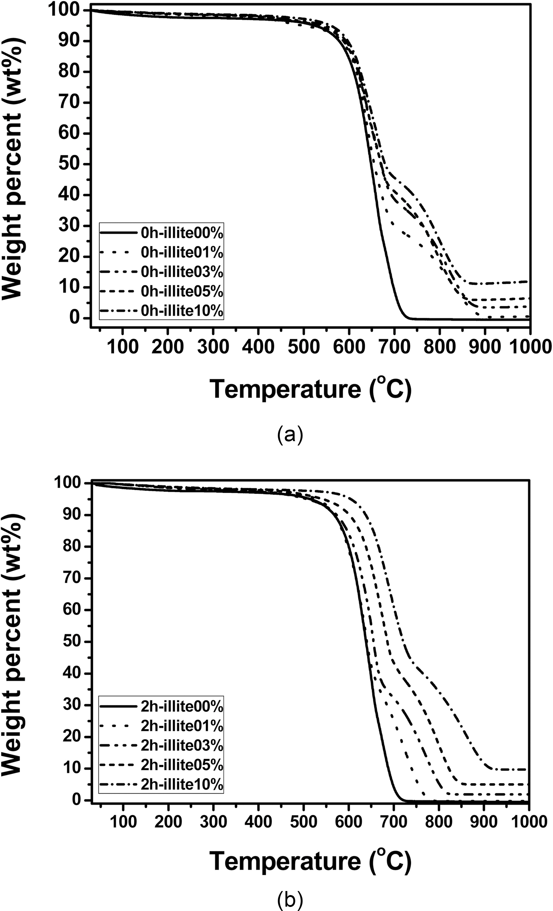
Thermal oxidation stability in air of the illite-C/C composites are shown in Fig. 5. Thermal oxidation stability of pristine illite-C/C composites is improved, as the amount of illite added increases. As a result, 10% of pristine illite added C/C composite has about 10℃ increased initial decomposition temperature (IDT), compared to that of the C/C composite without illite. In the same way, thermal oxidation stability of 2 h treated illite-C/C composites is also improved, as the amount of illite added increases. However, the improvement of 0 h illite-C/C composites is relatively small compared to that of 2 h illite-C/C composites. The IDT increase of the 10% 2 h treated illite added C/C composite is about 100℃. Compared to that of 10% 0 h illite-C/C composite, it is about 10 times more increase. This is attributed to the size reduction of illite, which improved its infiltration into carbon preform, resulting in more SiC formation.
There is another interesting change in the oxidation behavior of C/C composites after illite addition. In Fig. 5, the illite-C/C composites exhibit delay in oxidation between
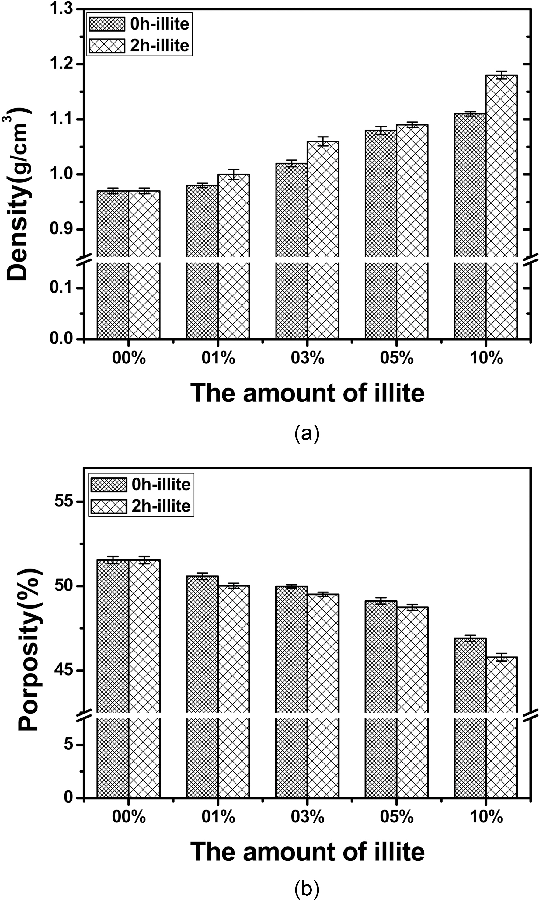
700 and 900℃. This delayed oxidation behavior is a unique finding which only can be observed when illite is used as filler. This may be attributed to the characteristic structure of illite itself. As we recall the chemical and physical structure of illite, it has a 2:1 basal layer which consisted of two layers of tetrahedral SiO2 and one layers of octahedral Al2O3. And those metal oxides have good affinity to free -OH of phenolic resin, so that illite can be tightly bound to phenolic resin during heat treatment after the resin impregnation. In addition, illite has the number of the 2:1 basal layers accumulated. The layered structure is reported to reduce the friction and it can assist infiltration of phenolic resin [14]. Therefore, illite assists infiltration or impregnation of phenolic resin, due to the synergistic effect of chemical and physical structure of illite. The improved impregnation of phenolic resin can be proved by bulk densities and porosities of the illite-C/C composites shown in Fig. 6. When pristine illite is added to C/C composites, bulk densities of 0 h illite-C/C composites are increased and porosities of them are
decreased, as the amount of pristine illite added increase. The similar trend is observed in the 2 h illite-C/C composites. But they have more increased bulk densities and decreased porosities, due to the effect of the size reduction. Therefore, the delay in oxidation seems to be attributed to illite in phenolic resin impregnated, due to its chemical and physical structure. Since the impregnation of the phenol resin into carbon preform is improved, the resultant C/C composites have less pores and voids inside the composites. The oxidation is a surface reaction which proceeds with oxygen attack on the surface and via diffusion of oxygen inwards to the composite. Therefore, when the composite has less voids and pores inside of it, the oxidation which occurs in the inner side of the composite can be delayed.
The size reduction of illite resulted in narrower particle size distribution and improved illite infiltration into carbon preform. And the resultant C/C composites prepared with that illite has even more improved thermal oxidation stability in air, showing more increased IDTs, compared to those of the C/C composites with pristine illite. Illite induced delay in oxidation of the illite-C/C composites is also observed and the delayed oxidation behavior is attributed to the layered structure of illite, which improved illite/phenol resin infiltration. Therefore, the potential use of illite as filler to improve oxidation stability of C/C composite can be promising. And size reduction of illite can improve its effect on the desired properties of illite-C/C composites even more.