Polymer materials have been widely utilized for many electrical parts because they have light density, easy processibility and cost-effectiveness. However, most of them are not electrically conductive and, as a result, not electromagnetically shielded. Nowadays, polymer materials with diverse functions including electrical conductivity and good mechanical properties are often needed in electrical and electronic applications. In the early studies [1-3], conductive fillers like metal powder, carbon black and carbon fiber were frequently added to polymers to provide the electrical conductivity. More recently, single-walled or multi-walled carbon nanotubes, carbon nanofibers and graphite or graphene nanoparticles have often been introduced to nonconductive polymer materials to increase the conductivity as well as the mechanical and thermal properties in a number of studies [4-9]. It has been known that the properties significantly depend on the distance between the carbon particles as well as the loading and the aspect ratio [10]
However, the dispersion of carbon fillers in a polymer has often become a critical issue to attain the material properties on purpose because there are some difficulties in uniformly dispersing them in the polymer, particularly at high loadings [11]. Here we propose that use of carbon nanofiber webs may solve such the dispersion problems because individual nanofibers consisting of the web with threedimensional network structure may be uniformly distributed in the resin matrix of a polymer composite upon processing properly. Furthermore, the web well-incorporated in the polymer may play a significant role in decreasing the electrical resistivity with lowering the filler content for reaching the percolation threshold. This may be possible because the dominant polymer matrix can be connected by individual nanofibers in the web if the web can be distributed uniformly through the thickness direction in the matrix of a composite. It may be expected that the incorporation of threedimensionally aligned nanofibers into the matrix can also provide a reinforcing effect to a composite system.
Recently, electrospinning technique has been increasingly utilized and well-reviewed [12]. A key merit of this technique is that nonwoven webs networked with a large number of ultrafine fibers or nanofibers can be easily processed with a small amount of starting materials [13,14]. Electrospun PAN nanofiber webs, which are not conductive, have the greater specific surface area with a much smaller fiber diameter in comparison with conventional PAN fibers. In order to obtain PAN-based carbon nanofiber webs from electrospun PAN nanofiber webs, stabilization and carbonization processes are critically important [15]. During the last years, a few studies [16-18] have reported on preparing and characterizing carbon nanofiber webs from electrospun PAN-based nanofiber webs. However, no reports on fabricating and characterizing polymer composites interleaved with carbon nanofiber webs (CNFW) have been found yet. Consequently, the objectives of the present study are, for the first time, to fabricate novel PAN-based carbon nanofiber web/unsaturated polyester composites and also to investigate their electrical resistivity, the thermal stability, dynamic storage modulus and the morphological change, depending on the content of CNFW incorporated into unsaturated polyester. This paper deals with composites consisting of electrospun PAN nanofiber web, the stabilized web or the carbonized web and unsaturated polyester resin as thermosetting matrix.
Polyacrylonitrile (PAN) with an average molecular weight of 150000 and a glass transition temperature of 85℃, which was purchased from Sigma-Aldrich Chemical Co., USA, was used as precursor for carbon nanofibers. N,N-Dimethylformamide (DMF) (extra pure reagent), which was used as solvent for electrospinning PAN, was purchased from Dae Jung Chemical. Co., Korea. Ortho-type unsaturated polyester (UPE, POLYSTAR UP-GR235) was supplied from Sewon Chemical Co., Korea and used as polymer matrix of composites in this work.
The concentration of PAN dissolved in DMF for electrospinning was 12 wt.%. This was because the optimal state of the PAN nanofibers obtained from electrospinning technique was obtained at 12 wt.% of PAN, as reported previously elsewhere [17]. The mixture of PAN/DMF was prepared by sufficiently stirring at 40℃ for 24 hours. For electrospinning, the applied voltage was 15 kV and the
spinning rate was 1 ml/min. The distance between a needle tip and a ground electrode was 180 mm. The ground electrode was covered with a layer of aluminum foil on a stainless steel drum. The take-up rate of the drum was 25 rpm. The electrospinning was performed at 31℃ with a relative humidity of 20%. A set of PAN nanofiber webs produced by electrospinning was sufficiently dried at ambient temperature in a vacuum oven prior to use.
2.3. Stabilization and carbonization processes of PAN nanofiber webs
Stabilization and carbonization processes were performed using a mullite tube-type Siliconit heat-treatment furnace (AJEON Heating Industrial Co., Ltd., Korea) according to pre-scheduled processing conditions. The inner diameter of the tube was 80 mm and the length was 1000 mm. The heating zone was about 300 mm in length and it was located in the center of the tube. The furnace was designed in order to control heat-treatment temperature, time and flowing gas rate. The electrospun webs resting on a graphite-plate were placed in the middle of the heating zone of the furnace and each end of the tube was sealed with a silicone lid.
Stabilization process was conducted purging air into the furnace at a constant rate. The stabilization temperature was 230℃ and the heating rate was 20℃/h. Carbonization process was performed purging a nitrogen gas (99.999%purity). The carbonization temperature was 1200℃ and the heating rate was 200℃/h. The nitrogen gas or air was also continuously purged during the cooling stage of the furnace.
2.4. Fabrication of nanofiber web/unsaturated polyester composites
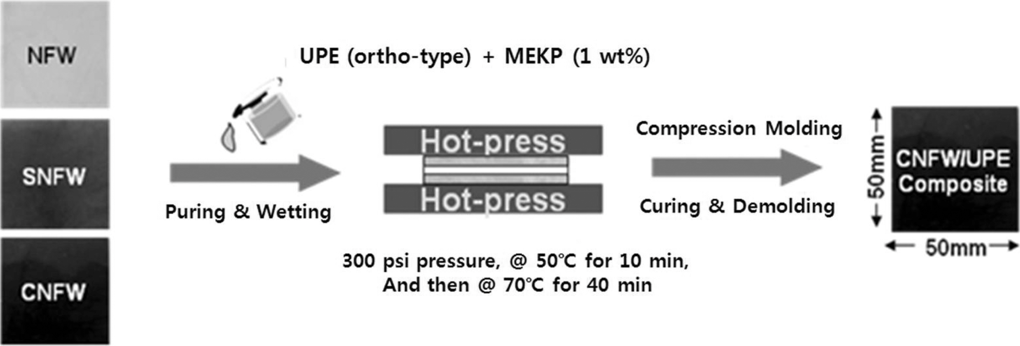
A small amount of unsaturated polyester resin was poured on the PAN nanofiber web, the stabilized nanofiber web and the carbonized nanofiber web, respectively. The resin was uniformly spread in the web using a roller. The roller was
used to enhance the wettability and the impregnation of the resin to the web. The web/UPE prepregs were prepared by resting them at ambient temperature for 2~3 min. Each of PAN nanofiber web/UPE, stabilized nanofiber web/UPE and carbonized nanofiber web/UPE composites was then processed at 50℃ for 10 min, and then 80℃ for 40 min under the pressure of 300 psi between two stainless steel plates by compression molding. After forming each composite, the hot-press was naturally cooled down. Each composite was obtained more like a thick film of 1 mm in average thickness. Fig. 1 shows schematic illustration of compression molding process to make three different types of composites above-mentioned. The contents of nanofiber webs interleaved in the composite were handled to be 2 wt.%, 4 wt.% and 8 wt.% respectively by using different layers of the webs. That is, one layer (~100 ㎛ in thickness) of the PAN nanofiber, stabilized or carbonized webs corresponded to 2 wt.%, two layers ~200 ㎛ in thickness) 4 wt.% and four layers ~400 ㎛ in thickness) 8 wt.%, respectively. The amount of UPE used for each composite during the composite fabrication was constant.
The electrical resistivity of neat UPE resin and web/UPE composites was measured at ambient temperature using a volume resistivity tester (IV/CV/PIV system with two probes, ACL STATICIDE Model 800). The average value of the volume resistivity of each specimen was obtained from three specimens. The dimensions of each specimen were 35 mm×3 mm×1 mm.
The dynamic storage modulus for neat UPE and web/UPE composites was measured using a dynamic mechanical analyzer (DMA Q800, TA Instruments, USA) purging a nitrogen gas. The heating rate was 5℃/min. The frequency used was 1 Hz and the oscillating amplitude was 0.2 mm.
The thermal stability of each specimen was measured up to 600℃ using a thermogravimetric analyzer (TGA, TA4000,TA Instruments) purging a nitrogen gas at 80 cc/min. The heating rate was 10℃/min.
In order to observe the fracture surfaces of neat UPE, PAN nanofiber web/UPE, stabilized web/UPE and carbonized web/UPE composites, a scanning electron microscope (SEM, S-570, Hitachi) was used. Each specimen was fractured in a liquid nitrogen bath and was uniformly coated with Au for SEM observations. The electron beam voltage of 15 kV was used throughout the work.
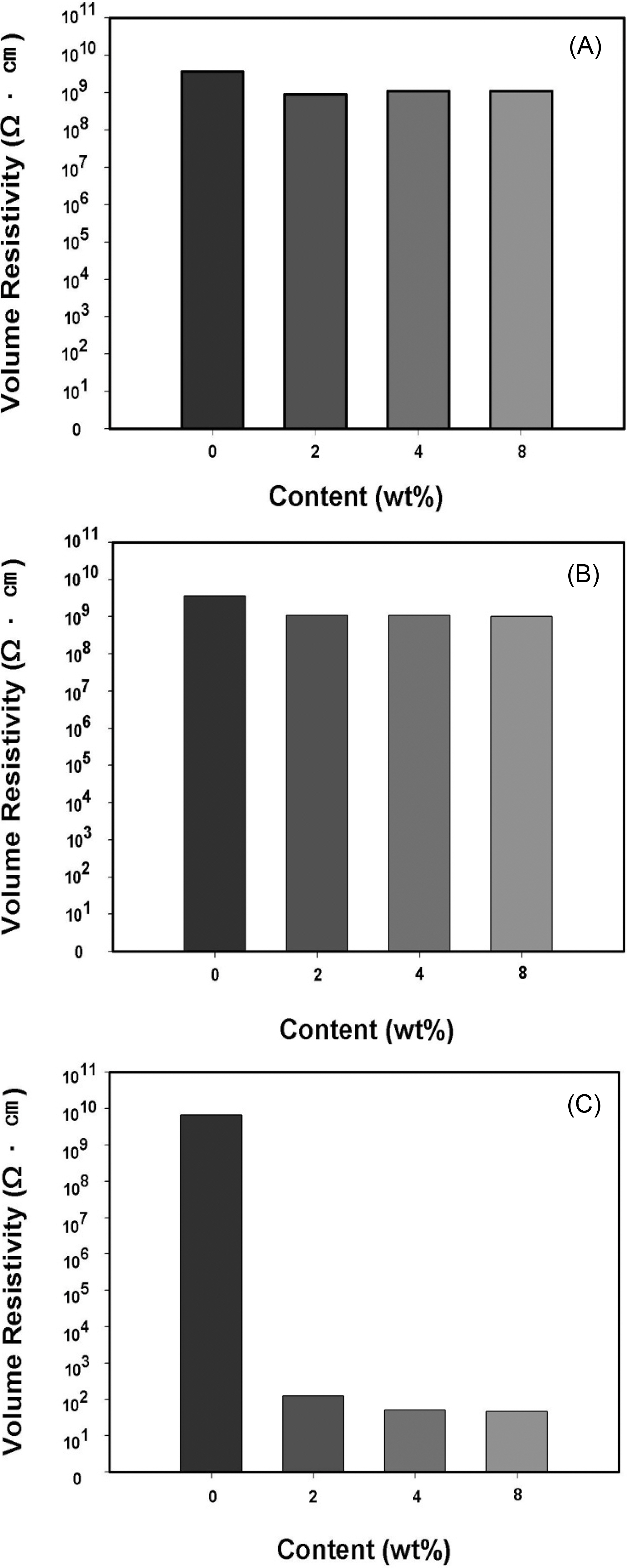
Fig. 2 displays the volume resistivity of PAN nanofiber webs (A), which were not heat-treated, the stabilized nanofiber webs (B) and the carbonized webs (C) measured
varying the web content. The result was compared with neat UPE. The volume resistivity of neat UPE was about 110Ω· cm. As expected, the resistivity of PAN nanofiber web/UPE composites was not changed significantly with increasing the web content, showing a value of about 110Ω· cm. The stabilized web/UPE composites exhibited similar volume resistivities with increasing the web content,compared with the PAN nanofiber web/UPE counterparts. This turns out that the stabilization, which was conducted at 230℃, did not contribute to lowering the resistivity of the PAN nanofiber web/UPE composite although the PAN nanofiber web in white was transformed in dark blown during the stabilization process.
On the other hand, the carbonized nanofiber web/UPE composite with the web content of 2 wt.% (one layer of the web) exhibited a largely reduced volume resistivity (~100Ω· cm) and the value was further decreased to about 100Ω· cm at 4 wt.% and 8 wt.%. Such a marked drop of the resistivity indicated that the percolation threshold may be occurred at 2 wt.% or less. The result also implied that the introduction of just one layer of the carbonized nanofiber web to UPE can contribute to providing the electrical conductivity to UPE resin. The remarkable reduction of the resistivity can be explained by that the UPE matrix was well distributed in the individual nanofibers of the carbonized web and the electrically conductive fibers, which were threedimensionally connected each other in the UPE matrix, played a major role in reducing the electrical resistivity of the composite. More interestingly, the result reflected that the individual nanofibers consisting of just one layer (~100 ㎛ in thickness) of the web were aligned through the thickness direction of the composite. It also turned out that the UPE resin was sufficiently infiltrated between the individual nanofibers of the web upon composite processing. The microscopic view of individual nanofibers surrounded by the resin will be given in the later part of this paper.
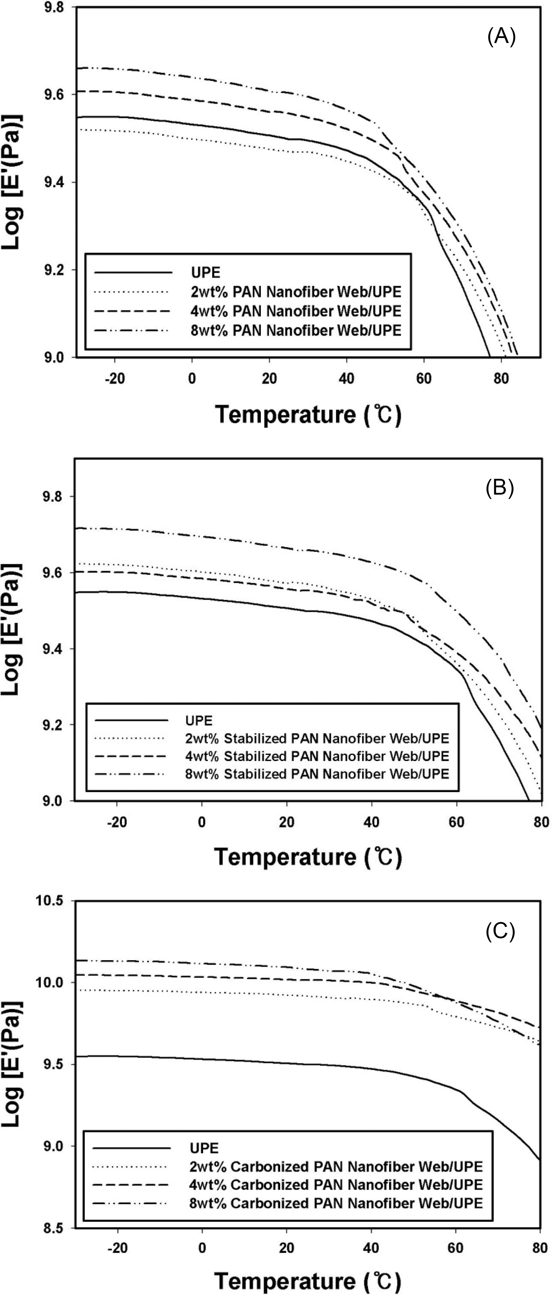
Fig. 3 exhibits the variation of the dynamic storage modulus measured using DMA for PAN nanofiber web/UPE (A), stabilized nanofiber web/UPE (B) and carbonized webs/UPE composites (C) measured at different web contents. Table 1 summarizes the storage modulus data collected at -25℃, 0℃, 25℃ and 50℃ for comparison, respectively. In Fig. 3A, the storage modulus of UPE in the temperature region below 56℃ was greatly increased by incorporating the PAN nanofiber webs more than 2 layers (4 wt.%) to UPE. At 25℃, the value was improved from 3.12 GPa to 4.02 GPa. The percent improvement of the modulus from neat UPE to 8 wt.% PAN nanofiber web/UPE composite was about 28~29% between -25℃ and 25℃ and about 20% at 50℃.UPE and all the composite samples showed the noticeable reduction of the storage modulus above about 60℃ due to the increased molecular mobility of the sample, leading to the increased flexibility of the sample. Measurements were conducted up to 80℃ because the sample could not retain
the rigidity of the sample beyond the temperature even though there was no thermal stability change up to 100℃ and higher, as can be seen in Fig. 4.
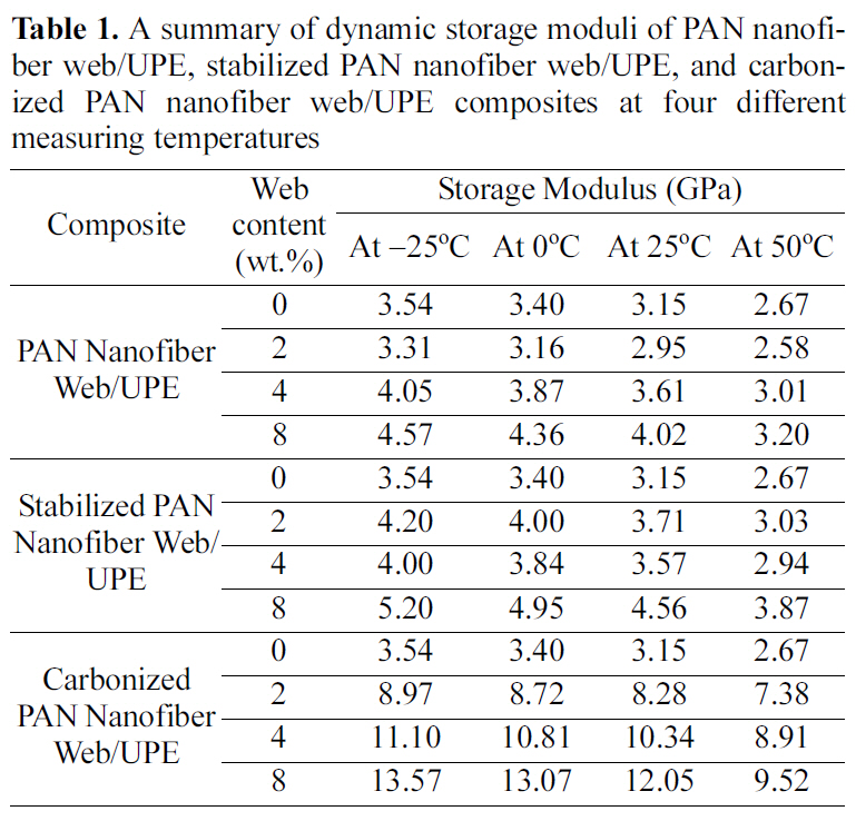
A summary of dynamic storage moduli of PAN nanofiber web/UPE stabilized PAN nanofiber web/UPE and carbonized PAN nanofiber web/UPE composites at four different measuring temperatures
In Fig. 3B, the incorporation of the web heat-treated at 230℃ during stabilization increased the modulus at all the web contents but there was no significant difference in the modulus between one layer (2 wt.%) and 2 layers (4 wt.%) of the web. The storage modulus was significantly increased at 4 layers (8 wt.%). As compared from Table 1, the storage modulus for neat UPE at 25℃ was improved to 4.56 GPa for 8 wt.% stabilized PAN nanofiber web/UPE composite by incorporating the PAN nanofiber webs more than 2 layers to UPE. The percent improvement of the modulus from neat UPE to 8 wt.% stabilized PAN nanofiber web/UPE composite was about 45~47% between -25℃ and 50℃.
The DMA result showed that the introduction of the carbonized nanofiber webs to UPE increased the dynamic storage modulus markedly, as displayed in Fig. 3C. As found in Table 1, the increase of the modulus was much higher than Fig. 3A and 3B. The modulus measured at 25℃ was increased from 3.15 GPa for neat UPE to 12.05 GPa for 8 wt.% carbonized PAN nanofiber web/UPE composite. The percent improvement of the storage modulus from neat UPE to 8 wt.% carbonized PAN nanofiber web/UPE composite was about 257~283% between -25℃ and 50℃. It is noticeable that the incorporation of just one layer of the carbonized nanofiber web to UPE greatly increased the storage modulus in the measuring temperature range, resulting in the improvement of 153% in comparison with neat UPE. In the case of 8 wt.%, the storage modulus of the carbonized nanofiber web/UPE composites at 25℃ was the greatest, among the samples.
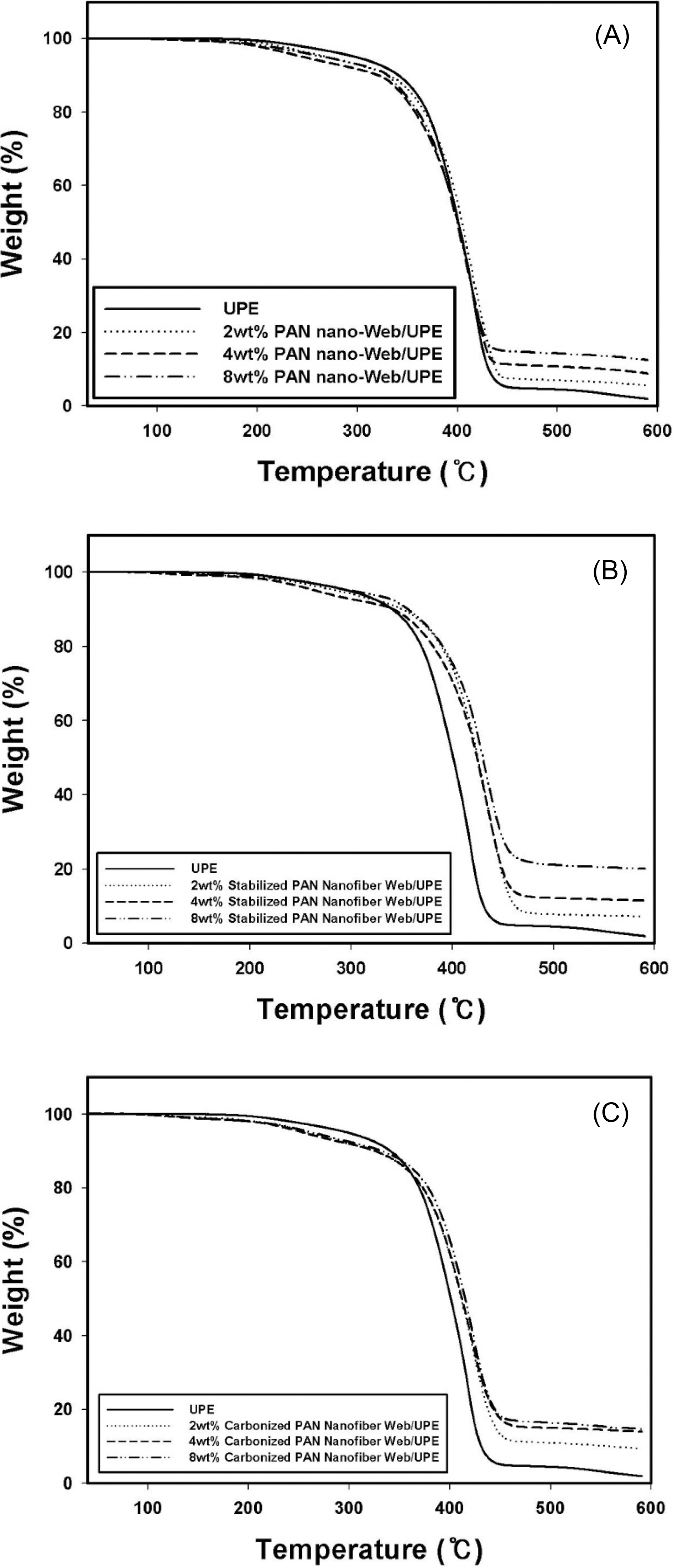
Fig. 4 shows the thermal stability of PAN nanofiber web/UPE (A), stabilized nanofiber web/UPE (B) and carbonized web/UPE composites (C) measured at different web contents. All the samples exhibited no weight loss to about
120℃. All the samples exhibited a similar pattern of the TGA curve. The primary weight loss was occurred in the range of 150℃~350℃ due to the incorporated webs and the
secondary weight loss was occurred beyond about 350℃ due to the degradation of UPE. The primary weight loss was somewhat greater in Fig. 4A than in Fig. 4B and 4C. It was found that the introduction of the nanofiber web to UPE did not increase the thermal stability of UPE below 350℃ but it contributed to enhancing the stability above 350℃, particularly with stabilized and carbonized nanofiber webs. It is also noted that the thermal stability in the high temperature region above 450℃ was obviously enhanced depending on the web content. The char yield of each sample was increased with increasing the web content and it has the greatest value at 8 wt.%. The char yield of the heattreated sample was greater than that of the untreated PAN nanofiber web with the corresponding web content.
With a close inspection of Fig. 4B for stabilized web/UPE samples and Fig. 4C for carbonized web/UPE samples, it seems that the thermal stability of the stabilized samples was more or less higher than that of the carbonized samples, exhibiting less weight losses with the same web content and
at the corresponding temperature. This can be explained by that the PAN nanofibers experienced a significant reduction in the fiber diameter during carbonization process and, as a result, the carbonized nanofiber webs consisted of individual fibers with a smaller fiber diameter than the stabilized webs. Therefore it may be said that the carbonized web/UPE composite contained the slightly larger amount of UPE resin than the stabilized web/UPE composite at the same web content and with the same sample dimensions. Accordingly, it was examined that more weight loss took place in the carbonized web/UPE sample at the same temperature during TGA measurement.
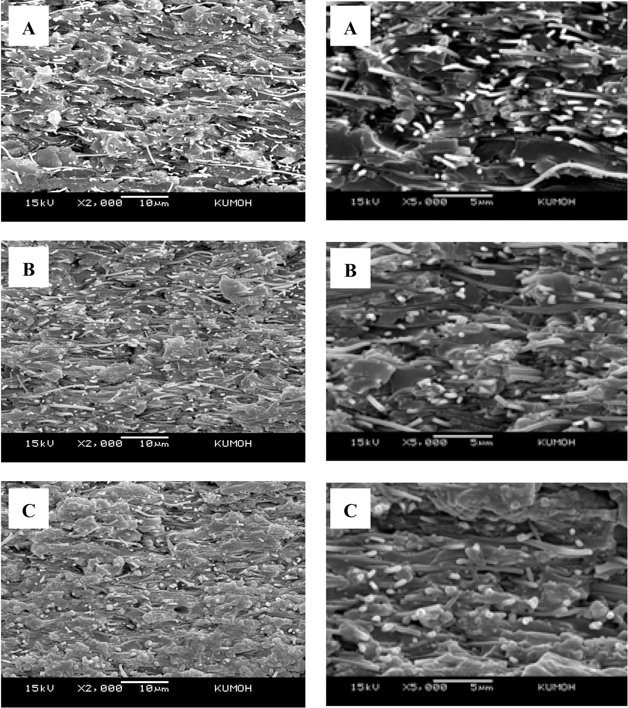
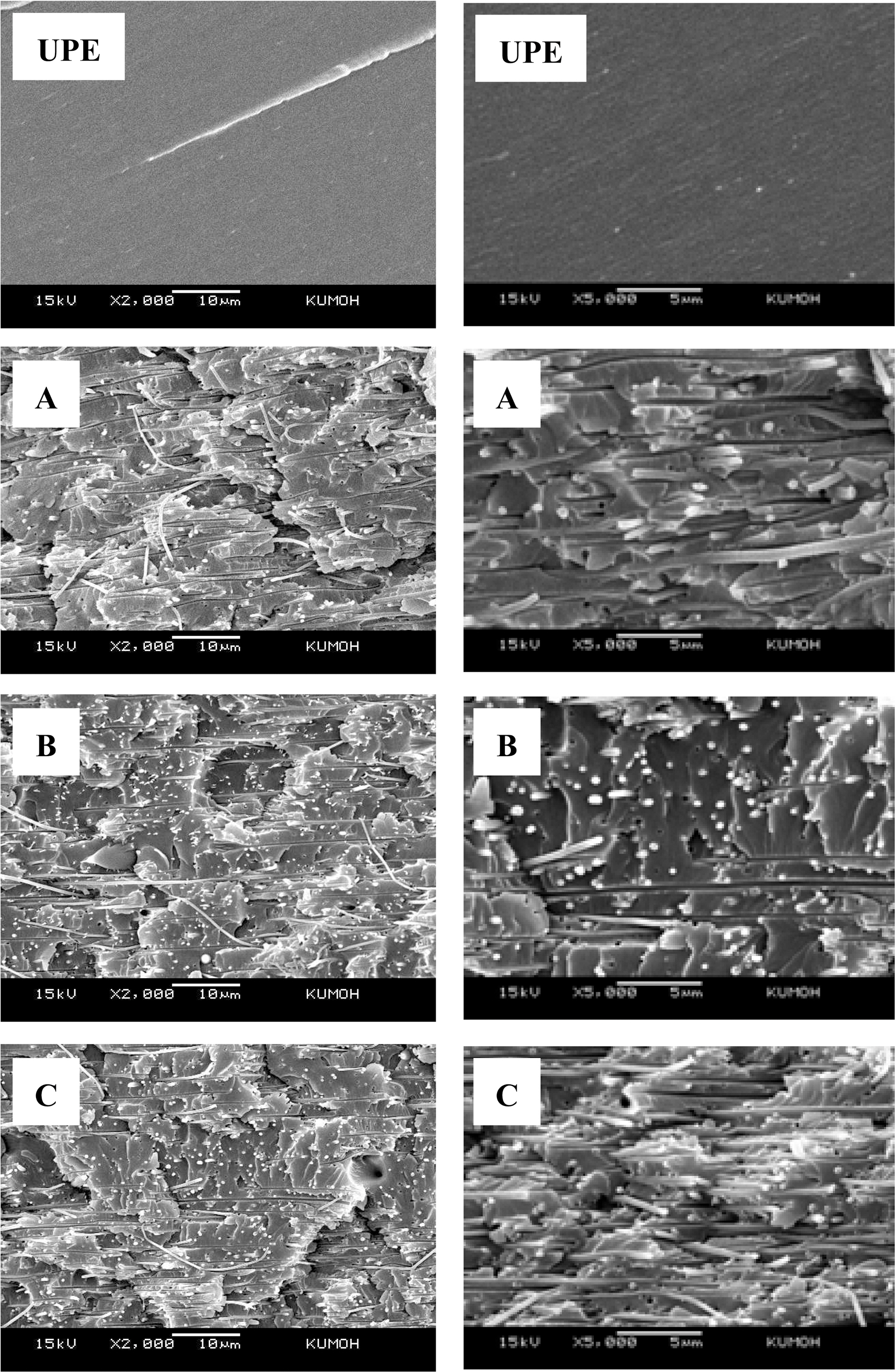
Figs. 5~7 present the fractured surfaces of PAN nanofiber web/UPE, stabilized nanofiber web/UPE and carbonized web/UPE composites observed at different web contents, respectively. The SEM images in the left of each figure were observed at a magnification of 2000 and those in the right were at a magnification of 5000. In Fig. 6 for UPE and PAN nanofiber web/UPE specimens, the UPE resin showed a typical fracture surface pattern of a thermosetting resin. It was found that the individual fibers in the web were uniformly distributed in each sample. With increasing the web contents more fibers were distributed in UPE matrix and the fractured surfaces became more ductile due to the presence of incorporated fibers therein. It was also seen that there were some pull-out fibers with a certain length.
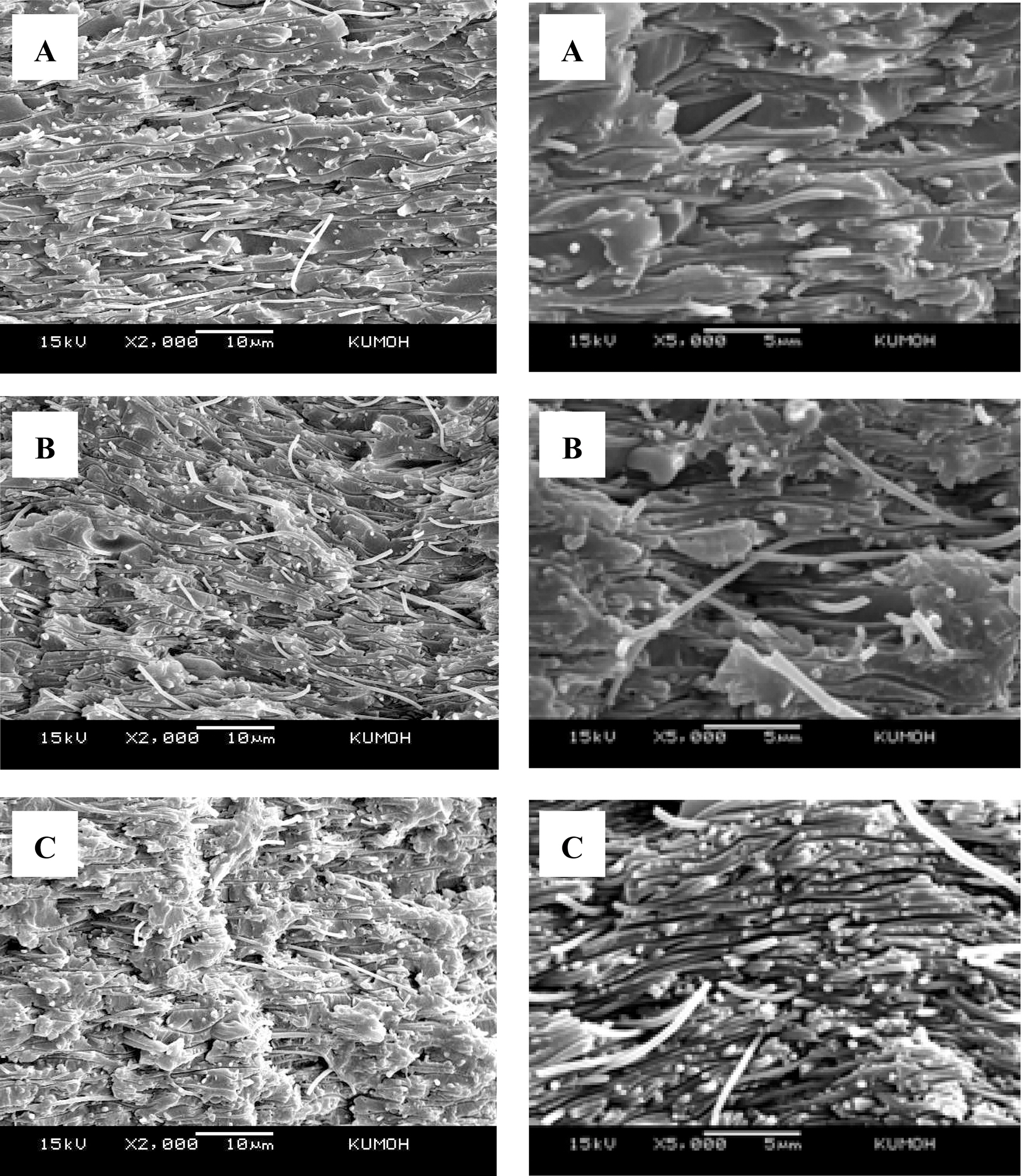
It seemed that the fractures surfaces of stabilized nanofiber web/UPE samples were rougher than those of PAN nanofiber web/UPE samples, as can be seen in Fig. 6. The stabilized fibers in the web may have more oxygencontaining functional groups, which can be introduced during the stabilization process done at 230℃ in air, than the PAN fibers without heat-treatment. Such the functional groups may contribute to enhancing the bonding between the fibers and the UPE during the composite fabrication, leading to a more ductile fracture pattern than in the PAN nanofber web/UPE sample. It was also observed that the fiber pull-out can take place in the samples.
As indicated in Fig. 7, the length of the pull-out fibers in the carbonized web/UPE composites was shorter than that of PAN web/UPE and stabilized web/UPE composites, as shown in Figs. 6 and 7. This is obviously due to the brittleness of carbonized fibers in the web. Due to the shortened fiber pull-out, it seemed that there exists much UPE resin on the fracture surfaces. It was also found that the carbonized fibers with a smaller diameter were distributed uniformly and more compactly in the matrix of the composite. In addition, it may be thought that the fiber modulus was increased after carbonization. And, the distance between the individual nanofibers aligned in the matrix became closer enough to provide the conductivity to the sample during compression molding of the composite. As a result, they played a role in reducing the electrical resistivity and also in improving the dynamic storage modulus. The relatively uniform distribution of individual fibers in the UPE matrix was observed similarly through the thickness direction of each composite sample.
1. In the present study, it has been investigated that the introduction of just one single layer (which is corresponding to 2 wt.%) of the carbonized nanofiber web to unsaturated polyester resin (UPE) can contribute to reducing the electrical resistivity of the resin markedly, resulting in the percolation threshold.
2. The DMA result demonstrated that the incorporation of PAN nanofiber, stabilized nanofiber or carbonized nanofiber webs into UPE resin greatly increased the dynamic storage modulus of UPE. In particular, the storage modulus measured at 25℃ was increased from 3.15 GPa for neat UPE to 12.05 GPa for 8 wt.% carbonized PAN nanofiber web/UPE composite. The percent improvement of the storage modulus from neat UPE to 8 wt.% carbonized PAN nanofiber web/UPE composite was noticeably about 257~283% in the temperature range of -25℃ to 50℃.
3. The introduction of the nanofiber web to UPE did not change significantly the thermal stability of UPE below 350℃ but it somewhat contributed to enhancing the stability above 350℃, particularly with stabilized and carbonized nanofiber webs. The char yield of each sample was increased with increasing the web content and it has the greatest value at 8 wt.%.
4. With increasing the content of PAN nanofiber web, more fibers were distributed in UPE matrix and the fractured surfaces became more ductile due to the presence of incorporated fibers therein. The fractures surfaces of stabilized nanofiber web/UPE samples were found to be rougher than those of PAN nanofiber web/UPE samples. The carbonized fibers with a smaller diameter were distributed uniformly and more compactly in the matrix of the composite. It seemed that the distance between the individual carbonized nanofibers aligned in the matrix became closer enough to reduce the electrical resistivity of the sample by compression molding. As a result, carbonized PAN nanofiber webs played a significant role in reducing the resistivity and also in improving the dynamic storage modulus.