Carbon nanotubes (CNTs) have attracted much interest due to their novel physical, chemical,and electrical properties [1] and their wide range of potential applications [2,3]. Depending upon their diameter, CNTs can behave as one-dimensional semiconductors or metals. To realize the full potential of CNTs, the controlled growth of high-quality material is essential.So far, many methods, including electric arc discharge [4], laser evaporation [5], chemical vapor deposition [6,7] and floating catalyst method [8], have been developed to produce CNTs
The objective of this study was to synthesize a large quantity of carbon nanotubes by an improved floating catalyst method, in which the size of catalyst particles is controlled by directly heating the catalyst precursor. This improved floating catalyst method can easily control the introduction yield of the hydrogen catalyst by changing the distance between the catalyst precursor and the reaction area. In addition, we found in the experiment that the introduction of sulfur causes a great increase in the yield of carbon nanotubes. In this paper,the influence of a sulfur containing additive (thiophene) on the growth of carbon nanotubes was investigated.
This is an Open Access article distributed under the terms of the Creative Commons Attribution Non-Commercial License(http://creativecommons.org/licenses/by-nc/3.0/) which permits unrestricted non-commercial use, distribution, and reproduction in any medium, provided the original work is properly cited.
Ferrocene has a purity of 98% mass fraction (Aldrich, Missouri, USA) and was used as a main source of catalyst. Toluene was used as a carbon source. Thiophene was used as a sulfur source for the co-catalyst. The concentration of ferrocene was from 1 wt% to 5 wt% of toluene. The concentration of thiophene was from 0 wt% to 60wt% of ferrocene.
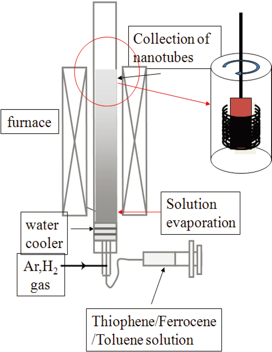
Fig. 1 shows the schematic setup of the vertical spray pyrolysis with bottom supply of mixture solution. Pyrolysis experiments were carried out in a two stage furnace system in a
flow reactor at atmospheric pressure. Ferrocene solutions were pumped (flow 10 mL/hr) into one end of the copper tube (3 mm i.d., 200 mm length) located in the first furnace (kept at 400°C)and sublimed into the main quartz tube (25 mm i.d., 1000 mm length). The synthesis of CNTs was achieved in a quartz tube located in the second furnace (kept at 800 to 1100°C).
The inner copper tube is the supply path for the mixture solution of toluene, ferrocene and thiophene, whereas the outer quartz tube is for the carrier gas. The mixture liquid is fed into the pre-heater through a small nozzle and vaporized at the end of the copper tube in the pre-heated zone. Argon gas was used as purging and inert gas in the quartz tube and as carrying gas for the liquid in the container to the hot zone of the quartz tube. Hydrogen gas was introduced from the entrance of the pre-heater to sweep the atomized reactant mixture into the hot zone of the furnace for reaction. By winding it with a motor, the outlet of the quartz tube was attached to a nanotube collector. The temperatures in the pre-heater and the hot zone were set at 400°C and from 800 to 1100°C,respectively.
The quartz tube reactor was pre-heated under inert gas to the desired pre-heating and reaction temperature; then, the inert gas flow was switched to the carrier gas mixture and the injection of liquid feed mixture was started. At the pre-heating temperature of 400°C, the liquid coming out of the capillary in the nozzle was immediately vaporized and swept into the reaction zone of the furnace by the flow of a mixture of hydrogen and argon with a flow rate of 1200 sccm. The flow rate of the liquid was maintained at 10~50 cc/hr and the liquid was be sprayed for 1 h. The collection of carbon nanotubes was completed by winding with a winder located at the end of the quartz tube. After completion of the hydrocarbon deposition process, the quartz tube reactor was cooled down to room temperature. The CNTs deposited in this way collected on the inner wall of the quartz tube in a thick black deposition. The morphology and microstructure of the as-synthesized products were analyzed using scanning electron microscopy (SEM, Hitachi S4800; Hitachi, Tokyo, Japan) and transmission electron microscopy (TEM, JEOL 2010; JEOL,Tokyo, Japan).
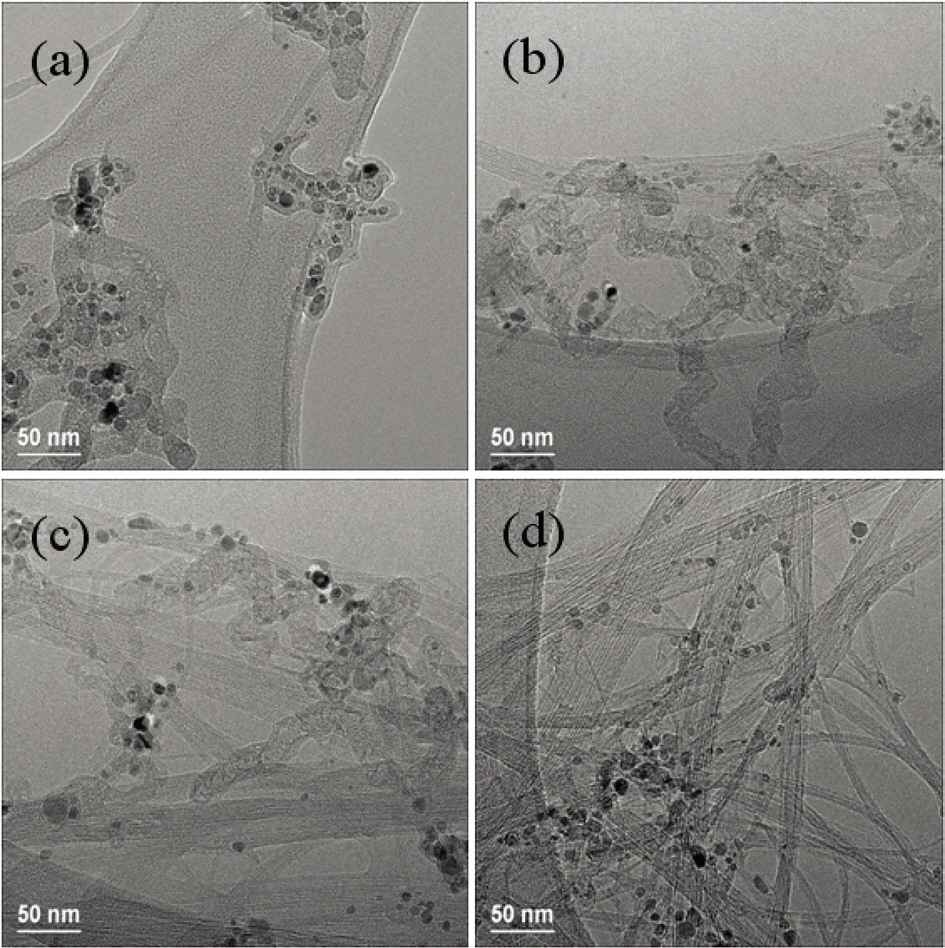
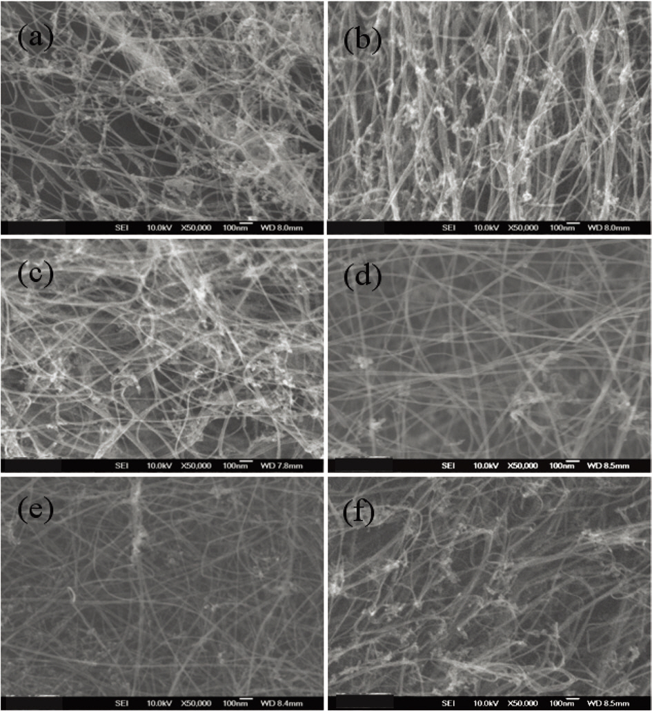
First, to find the appropriate temperature for the pyrolysis of toluene, four experiments were carried out at different temperatures:800, 900, 1,000 and 1,100°C. The flow rates of hydrogen and argon gas were set at 1,000 and 500 sccm, respectively, and the supply amount of solution mixture was set at 10 cc/h in the four experiments. The products obtained at 800 and 900°C show little carbon deposition or carbon nanotubes, as shown in Fig. 2a and b. The products from 1,000 and 1,100°C show nanotube morphology, as can be seen in Fig. 2c and d. These carbon nanotubes have a diameter distribution from 1 to 3 nm and look as though they have a single wall or double walls. The carbon nanotubes were formed when the reaction temperature was higher than 1,000°C (Fig. 2c). From the experimental results,it can be concluded that toluene has a very low decomposition and reaction activity on ferrocene catalyst if the temperature is below 1,000°C. So, the reaction temperature for the subsequent experiments was set at 1,100°C.
In order to understand the influence of the concentration of ferrocene and thiophene on CNT growth by the pyrolysis of toluene, a set of experiments was performed at the tem-
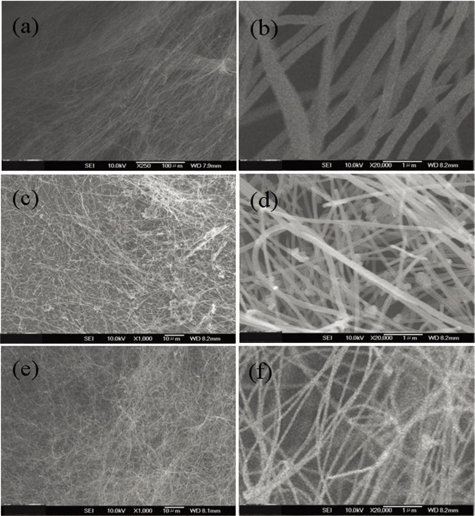
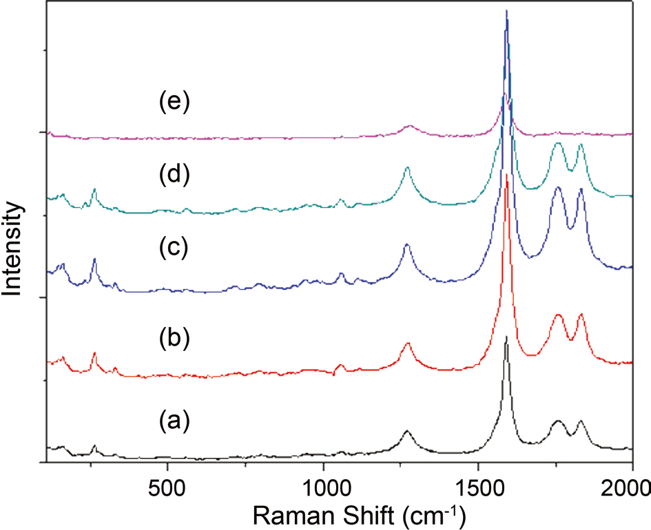
perature of 1,100°C. The amount of ferrocene was changed from 1 wt% to 5 wt% of toluene and that of thiophene was changed from 10 wt% to 60 wt% of ferrocene. Fig. 3 shows that when the ratio of ferrocene to toluene was 1 wt%, there is a change in the morphology of carbon nanotubes with the different concentration of thiophene. By increasing the thiophene,the content of carbon nanotubes was increased, and then decreased slightly with a further increase of thiophene.In the case of 1wt% ferrocene of toluene, good products were achieved when the addition of thiophene was from 20 to 40 wt% of ferrocene, as is shown in Fig. 3a-c. Fig. 4 shows Raman spectra of 1 wt% ferrocene of toluene. The ratio of G peak to D peak increased and decreased slightly from 3 to 8 with the increase of thiophene, which is similar to the results shown in Fig. 3. These changes in the Raman ratio were due to the nanoparticles that took part in synthesis of carbon nanotubes, the amount of which increased with the ratio of thiophene to ferrocene.
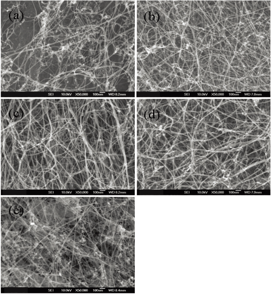
Fig. 5 shows the morphologies of the as-grown carbon nanotubes with 5 wt% ferrocene of toluene. The figure shows the slight shift range due to the thiophene addition compared with the shift due to 1 wt% ferrocene. When the amount of thiophene was from 30 wt% to 50 wt%, more carbon nanotubes were found, as can be seen in Fig. 4.
It can be deduced that a suitable level of sulfur can greatly promote the activity of catalyst Fe particles, resulting in the existence of a larger quantity of catalyst Fe particles whose size is appropriate for the growth of carbon nanotubes in the vapor phase. Tibbetts et al. [9] thinks that small quantities of sulfur can liquefy iron particles and enhance filament nucleation.Higher sulfur concentration in catalyst particles moves
the melting point above the eutectic, thus decreasing the efficiency of filament growth. After studying the preparation of carbon fibers coiled by pyrolysis of acetylene using an Ni catalyst and sulfur or phosphorous compound impurities,Motojima et al. [10] asserted that excess amounts of sulfur might act as a poison on Ni catalyst particles. Further studies need to be done to elucidate the effect of sulfur on catalyst particles. Kim et al. [11] found that pretreatment of cobalt in low levels of H2S has a dramatic effect on the ability of the metal to produce filamentous carbon. In contrast, when the
metal was pretreated at higher H2S levels, the catalytic action was suppressed. It is suggested that enhancement of carbon deposition following treatment at low levels of H2S is related to a reconstruction of the metal surface coupled with a blocking action of surface sulfur atoms towards the formation of a graphitic overlayer. Further studies need to be done to elucidate the effect of sulfur on catalyst particles.
To define the productivity of our pyrolysis system, we investigated the influence on the morphology of carbon nanotubes of the feeding rate of a mixture solution. The feeding rate was controlled at rates from 10 to 50 cc/h. Fig. 6 shows the morphology of the carbon nanotubes according to the feeding ratio of the solution. When the feeding ratio increased,carbon nanotubes decreased and amorphous carbon materials were coated on the carbon nanotubes. From this, it is evident that a higher feeding ratio leads to more toluene
being decomposed and to higher production of non-involved carbon materials in the synthesis of carbon nanotubes. It seems like that the carbon materials were sticky and so eventually covered the carbon nanotubes.
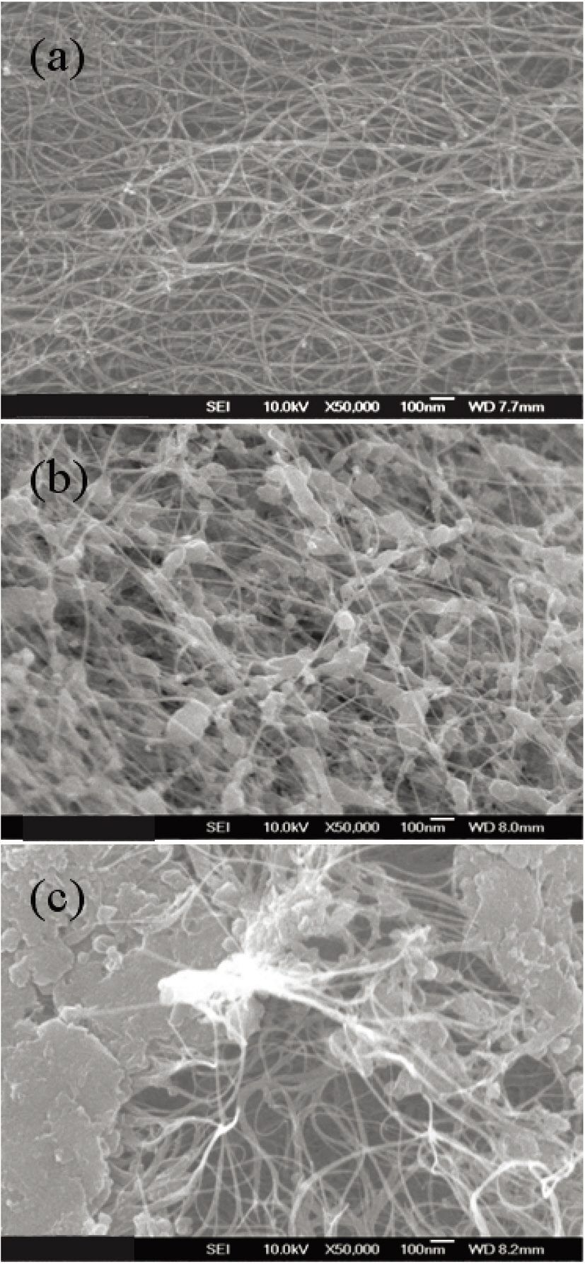
Finally we investigate the change of carbon nanotubes with the change of the flow ratio of hydrogen and argon. With increasing argon flow, much more black smog was produced and the quartz tube was bunged with gray-colored materials. After cooling down to room temperature, the samples were collected in the center of the quartz tube and analyzed. Fig. 7 is a SEM image of the sample prepared at hydrogen/argon flow rates of 100/1000, 250/850 and 500/600 sccm. It is demonstrated that the diameters of the carbon nanofiber decreased with the increase of hydrogen. It was assumed that less iron catalyst was formed by the etching effect of hydrogen.
In this study, we showed the effects of synthesis temperature,amount of ferrocene and thiophene as catalyst source and sulfur source, and flow ratio of hydrogen and argon gases on the morpholoy of grown carbon nanotubes. Lower amounts of ferrocene and higher temperature synthesis at higher temperature brought a higher yield of carbon nanotubes. For thiophene,the increase of the amount of this compound led to a reduction of the increase of the yield of carbon nanotubes.In the case of the gas ratio of hydrogen and argon, carbon nanofibers were synthesized in the center of reactor, and the diameter of the carbon nanofibers was found to increase with the increase of the argon flow.