Toxic organic halogens especially the chlorinated organic compounds are widely liberated from many industries into the water stream. Industries manufacturing dichloromethane,plastic products, synthetic products, urethane foam, electronic polyvinyl chloride (PVC) and the paint industries act as a source of liberation of trichloroethylene (TCE) and dichloromethane (DCM) [1]. Exposure to high concentrations of these chemicals may cause unconsciousness and death.Many research works on the removal of TCE and DCM using surfactants [2], ozone, radiation [3], electron beam [4,5],trickling filters [6] etc have been reported in the literature.Other granular media namely sandy loam soil, organic top soil, peat moss and granular activated carbon (GAC) have been reported to effectively adsorb these neutral chlorinated organic compounds [7]. Among various other methods,adsorption using activated carbon which is prepared from agricultural material is considered as a stand alone method for the removal of such compounds in highly economical way [8].
Activated carbon after the process of adsorption can be reused if the adsorbed chlorinated organic compounds are removed.This process is known as ‘regeneration.’ Thermal regeneration inevitably results in the loss of activated carbon. Also, thermal methods may not be the most efficient, inexpensive, or reliable method, so a number of solvents, acids and alkalis may be employed to remove the adsorbed substances. These include isopropanol, acetone, hydrochloric acid, hydrogen peroxide,potassium hydroxide and sodium hydroxide. Optimization of the regeneration process depends on the substances adsorbed as well as the structure of the activated carbon [9].
The present study aims in the removal of two neutral chlorinated organic compounds namely TCE and DCM from aqueous solution using low cost activated carbon prepared from coconut shell. The study also aims to compare the efficiency of the activated carbon with commercially available carbon, interpretation of the data with models namely BDST and Thomas model, regeneration of the activated carbon using suitable elutant.
Although batch laboratory adsorption studies provide useful information on the application of adsorption for the removal of specific waste constituents, continuous column studies provide the most practical application of this process in wastewater treatment. This is attributed to the reason that the high adsorption capacities in equilibrium can be achieved with the influent concentration rather than the effluent concentration [10].
The effect of bed height and flow rate on the adsorption of these compounds with the activated carbon (CSAC and CAC) of particle size 500 ㎛ to 1 mm were studied using column procedure. The column experimental run were performed at the solution natural pH.
The procedure for the preparation of activated carbon from
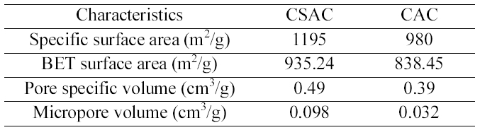
[Table 1.] The Characteristics of CSAC and CAC used in this Study

The Characteristics of CSAC and CAC used in this Study
coconut shells and the characteristics of CSAC and CAC were furnished in detail in our previous paper [11]. The specific surface area, BET surface area, pore specific volume and micropore volume of CSAC and CAC used in this study were summarized in Table 1. All the chemicals used were of analytical reagent grade. All the reagents and stock solutions were prepared with double-distilled water. Coconut shell based commercial granular activated carbon (particle size 500 ㎛ - 1 mm) was purchased from Anand Carbons,Tuticorin, India. AOX (Absorbable Organic Halides)analyzer (IDC Analytical system, Multi X 2000, Germany)was used for the analysis of the chlorinated organic content.
A glass column with 2.7 cm internal diameter and 30 cm long was used for continuous flow experiment. A small quantity of glass wool was packed at the bottom of the column to prevent escape of activated carbon in elute.Activated carbon was weighed to the required quantity and passed into the column. Distilled water was filled and then drained to get uniform packing of activated carbon. The organic solution of 200 mg/L was passed through the activated carbon at known flow rate and elute was collected at regular intervals for the determination of solution concentration. Operation of the column was stopped when the effluent solution concentration exceeded a value above 199 mg/L for both TCE and DCM.
Conditions
Bed Height used : 15, 20, 25 cm
Flow rate : 5, 10 and 15 mL/min
Flow rate during regeneration cycle : 5 mL/min
Feed Solution Concentration : 200 mg/L
Feed pH : 2.0
Temperature :Room temperature (27± 1oC)
Regeneration is an important step to reuse exhausted activated carbon. After the column reached exhaustion, the activated carbon loaded with the organic halide solution was regenerated using selected elutant at a flow rate of 5 mL/min. After elution, the bed was thoroughly washed with distilled water until the pH of the wash effluent stabilized near 7.0. The activated carbon was then dried at 60oC for 12 h and the column was fed again with organic halide solution and the sorption studies were carried out. These cycle of sorption followed by desorption were repeated for five times to evaluate the adsorption capacity of the activated carbons and weight loss of the activated carbon was determined in each cycle.
As the adsorbate solution passes through the column, the adsorption zone (where the bulk of adsorption takes place)starts moving out of the column and the effluent concentration start rising with time. This is termed as breakthrough point. The time taken for the effluent concentration to reach a specific breakthrough concentration of interest is called the break through time [12]. The total quantity of organic halides adsorbed in the column (Mad)was calculated from the area above the breakthrough curve(outlet solution concentration versus time) multiplied by the flow rate. Dividing the solution mass (Mad) by the adsorbent mass (m) leads to the uptake capacity (Q) of the activated carbon [13]. The total breakthrough time (tb, the time at which solution concentration in the effluent reached above the permissible limit) and bed exhaustion time (te, the time at which solution concentration in the effluent exceeded 199 mg/L) were used to evaluate the overall sorption zone (t)as follows using equation (1).

The length of the mass transfer zone (Zm) also called as critical bed length, was calculated from the breakthrough curve as follows using equation (2).

Where, Z is the bed height (cm). Effluent volume (Veff)was calculated as follows equation (3) [12].

Where, Z is the volumetric flow rate (mL/min). Total amount of TCE/DCM entering the column (Mtotal) was calculated as with equation (4).

Total solution removal percentage with respect to flow volume was calculated as using equation (5).

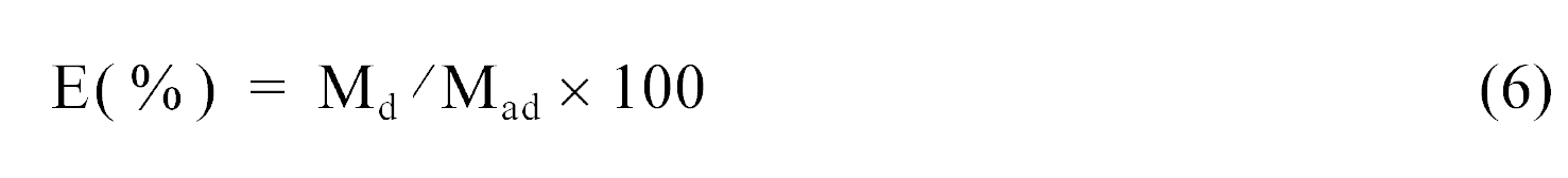
The TCE/DCM desorbed mass (Md) from the elution curve(Concentration versus time) and the elution efficiency (E)were calculated from the following equation (equation (6)).
2.5.1. BDST model
The relationship between the bed height (Z) and the service time (t) can be elucidated using the BDST model.The bed depth service time (BDST) model proposed by Bohart and Adams [14] assumes that equilibrium is not instantaneous. Therefore, the rate of the sorption is proportional to the fraction of sorption capacity which still remains on the sorbent [15]. The equation (7) is as follows

Where C0 is the adsorbate concentration in the inflow to the column (mg/L), Ce is the breakthrough concentration in the effluent (mg/L), K is a velocity constant (m3 of solution/kg of adsorbent s, N0 is the adsorption capacity (kg of adsorbate/m3 of adsorbent), D is the adsorbent height in the column (m), V is the linear velocity (m/s), t is the time of operation (s).
Hutchins [16] reported the simplest approach and most rapid prediction of adsorber performance as shown in equation (8).

Where N0 is the sorption capacity of the bed (mg/L), C0 and Cb the initial and the breakthrough solution concentrations respectively (mg/L), ν the linear velocity(cm/h) and Ka the rate constant (L/mg·h).
2.5.2. Thomas model
Various mathematical models can be used to describe the fixed bed experiment, among these Thomas model is simple and widely used by several investigators [12,17]. The linearised form of Thomas model is expressed as in equation (9).

Where kTH is the Thomas model constant (L/mg·h), Q0 the maximum solid phase concentration of the solute (mg/g), V the throughput volume (L). A plot was drawn using Ln ((C0/C)-1)against time and the KTH and the Q0 values obtained at different flow rates for PCP/TCP using both the activated carbons
Initially, batch experiments for treatment were performed to optimize particle size, adsorbent dosage and pH for maximum adsorption. Effect of pH on the adsorption of TCE and DCM on CSAC and CAC were studied by changing the pH from 1 to 11 maintaining the other parameters like carbon dosage (500 mg), solution concentration (50 mg/L)and particle size (250 ~ 125 ㎛) constant. The pH trend was similar i.e., there was no considerable effect for all the five chlorinated compounds studied irrespective of the carbon used. Since both the chlorinated compounds are non-polar organic compounds, the pH is not expected to affect the capacity as was observed. But percentage removal for all the compounds was high due to their hydrophobic nature.
The effect of adsorbent dosage on TCE and DCM by CSAC and CAC was examined by varying dosages from 10 to 1000 mg/100 mL. TCE saturation level reached at 700 mg/100 mL using both CSAC and CAC, DCM 400 mg/100 mL using CSAC and 500 mg/100 mL using CAC.
Two different particle sizes (125 ~ 250 ㎛ and<125 ㎛)were tried. For both the compounds only slight variation in uptake capacity and percentage removal efficiency were observed for both the particle sizes. Even though the smaller particle size resulted in slightly better adsorption performance compared to the larger size, its increase in uptake and removal efficiency were only 3% and 4% higher than the particle size of 125 ~ 250 ㎛ for TCE using CSAC and CAC, 3% and 6% for DCM using CSAC and CAC.
The effect of agitation time and initial concentration(50 mg/L to 1000 mg/L) on the removal of both chlorinated organic compounds namely TCE and DCM by CSAC and CAC was studied. For both the compounds the adsorption rate was fast and also the attainment of equilibrium time increased with increasing concentration of the solute. The total uptake of the chlorinated compounds increased along with the concentration but the percentage removal decreased.The contact time was fixed at 210 min for batch experiments(a concentration of 50 mg/L was used) to make sure that the equilibrium was reached in all cases.
The data were correlated using adsorption rate constants namely first and second order kinetics. All the compounds studied, obeyed second order rate kinetics irrespective of the carbon used. The sorption isotherm obtained at different concentrations were fitted using Langmuir, Freundlich,Redlich-Peterson and Sips models. It was interesting to note that TCE adsorption using both CSAC and CAC showed best fit for both Freundlich and Sips isotherm model indicating a heterogenous adsorption of the TCE at the surface of both the carbons. The regression data of both the models were found to be very close. Sips isotherm was found to be best fit for the data obtained by the adsorption of DCM on both CSAC and CAC than other models.
In desorption studies, different elutants (10% to 30% of acetone and 10% to 30% of isopropyl alcohol) were screened to identify the most efficient one for the compounds examined using both the carbon. 25% isopropyl alcohol was found to be efficient for the desorption of both the carbon. Thus the column experiments were carried out at the solution’s natural pH.
To yield different bed heights on an average of 22, 33 and 42 g of CSAC and 25, 34 and 45 g of CAC were used to
produce bed heights of 10, 20 and 25 cm respectively.Experiments on effect of bed height showed a decrease in minimum effluent concentration with bed height keeping other parameters constant. Minimum effluent concentration
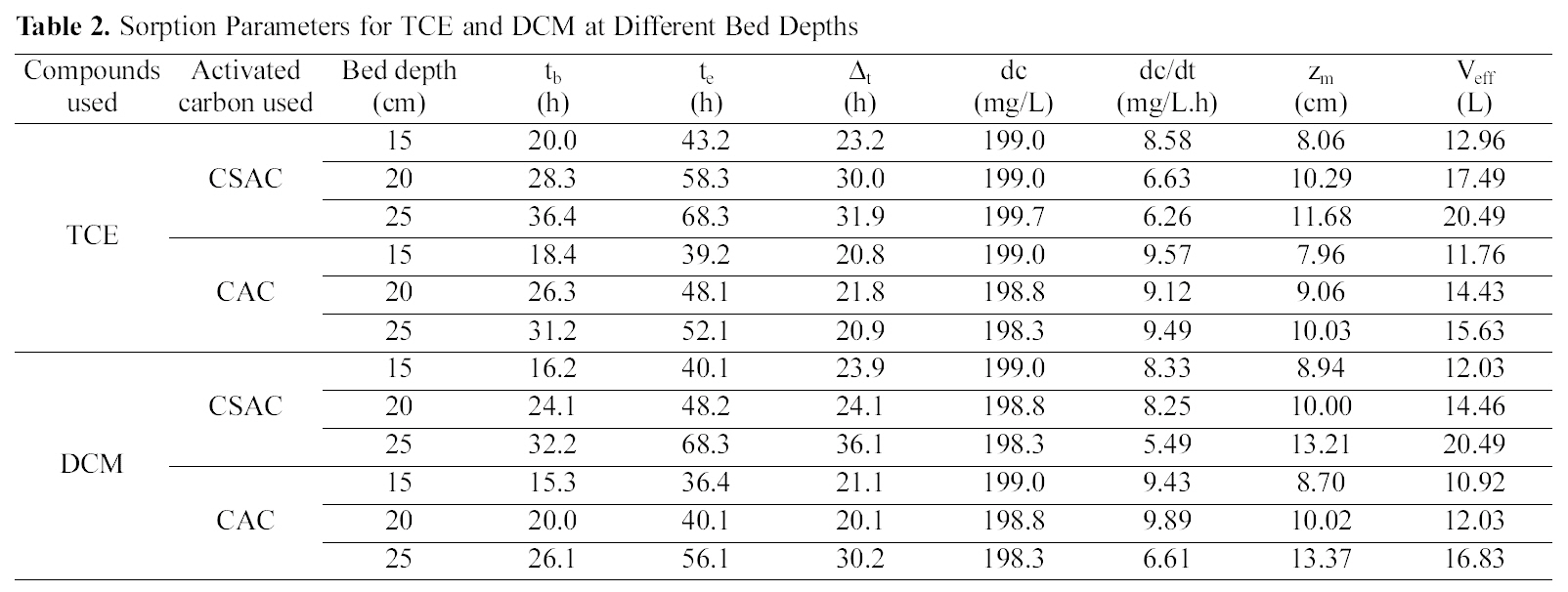
[Table 2.] Sorption Parameters for TCE and DCM at Different Bed Depths

Sorption Parameters for TCE and DCM at Different Bed Depths
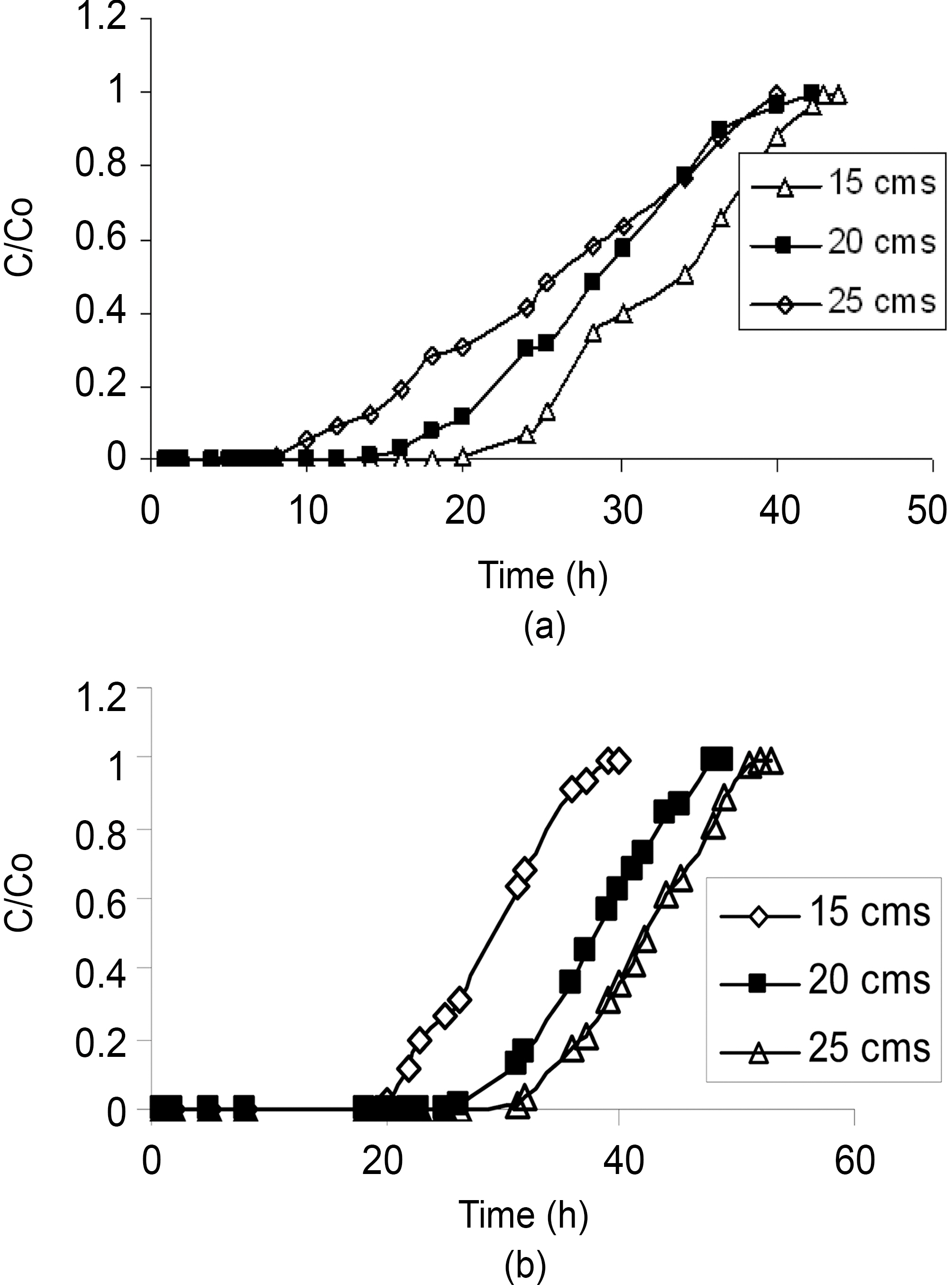
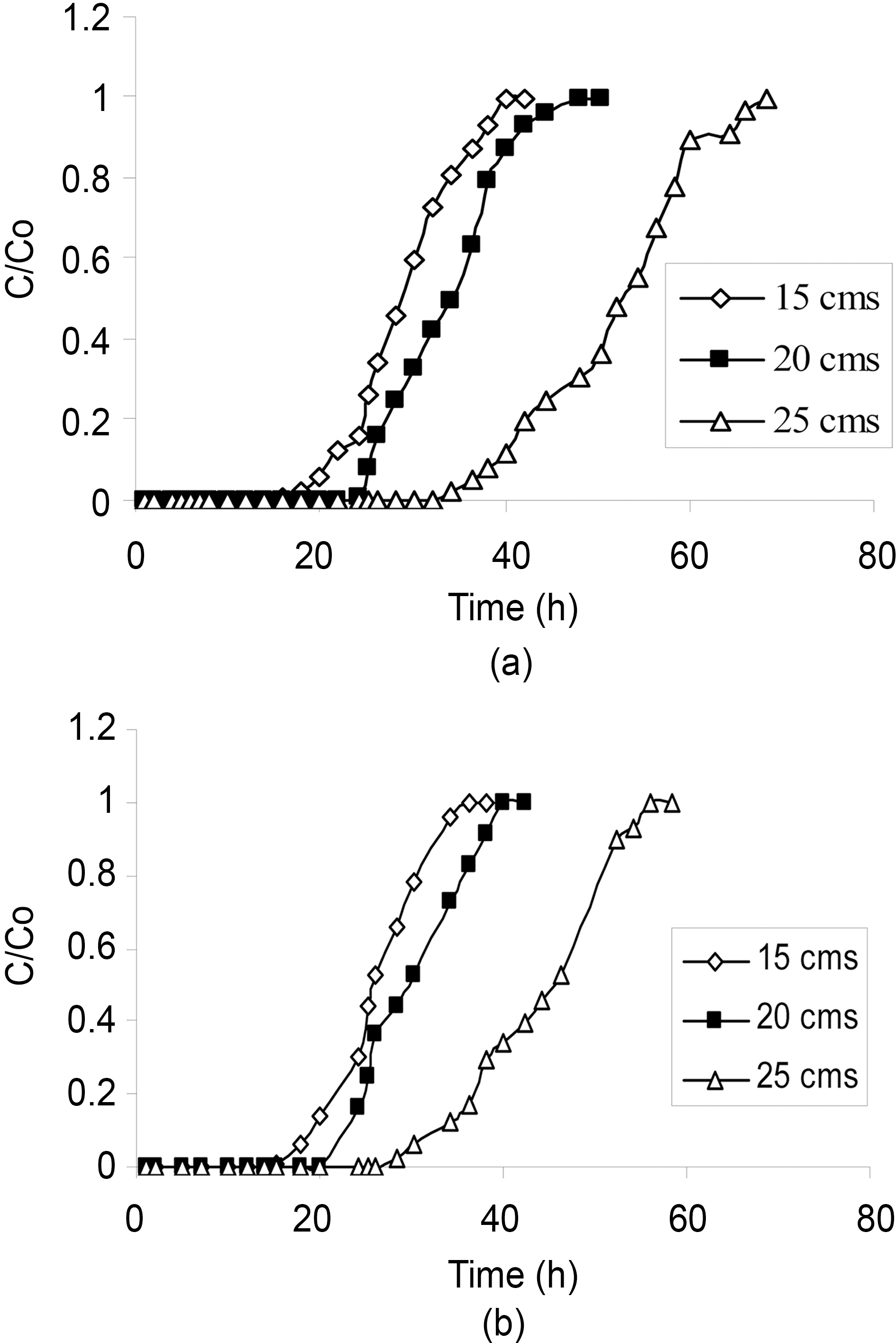
is defined as the average concentration of the pollutant at the column outlet (or effluent) in initial constant phase. As the bed height increases, the length of the bed through which the
effluent passes also increases. The increase in the total adsorptive capacity of the bed results in a decrease in the solute concentration in the effluent. Fig. 1 and 2 show the breakthrough profiles for both TCE and DCM respectively,at different bed heights. There was no change in the adsorption zone length or in the speed of the zone. The breakthrough time (tb) and the exhaustion time (te) were increased with an increase in the bed height for all the compounds invariably the activated carbon used (Table 2).From the data it was well predicted that both the breakthrough time and exhaustion time reached earlier in most of the cases for both the compounds using CSAC than CAC, showing the better efficiency of CSAC than CAC in the adsorption of both the compounds studied.
The slope of the S-curve from tb to te decreased as the bed height increased from 15 to 25 cm, indicating that the breakthrough curve becomes steeper as the bed height decreases. The change in the slope of the curve with increasing bed height can be explained, again on the basis of mass transfer processes. For small bed heights, where the adsorption zone is of the order of the bed height, the adsorption zone reaches the bed bottom near the beginning
[Table 3.] Parameters Derived for Thomas Model for TCE and DCM Adsorption Onto CSAC and CAC
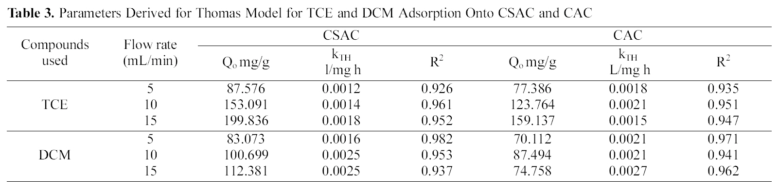
Parameters Derived for Thomas Model for TCE and DCM Adsorption Onto CSAC and CAC
of the run, resulting in a rapid rise in effluent concentrations right from the start. As the bed height increases much beyond the length of the adsorption zone, an appreciable period of time elapses before the zone reaches bed bottom.As such, low effluent concentrations are obtained in the beginning of the run [18].
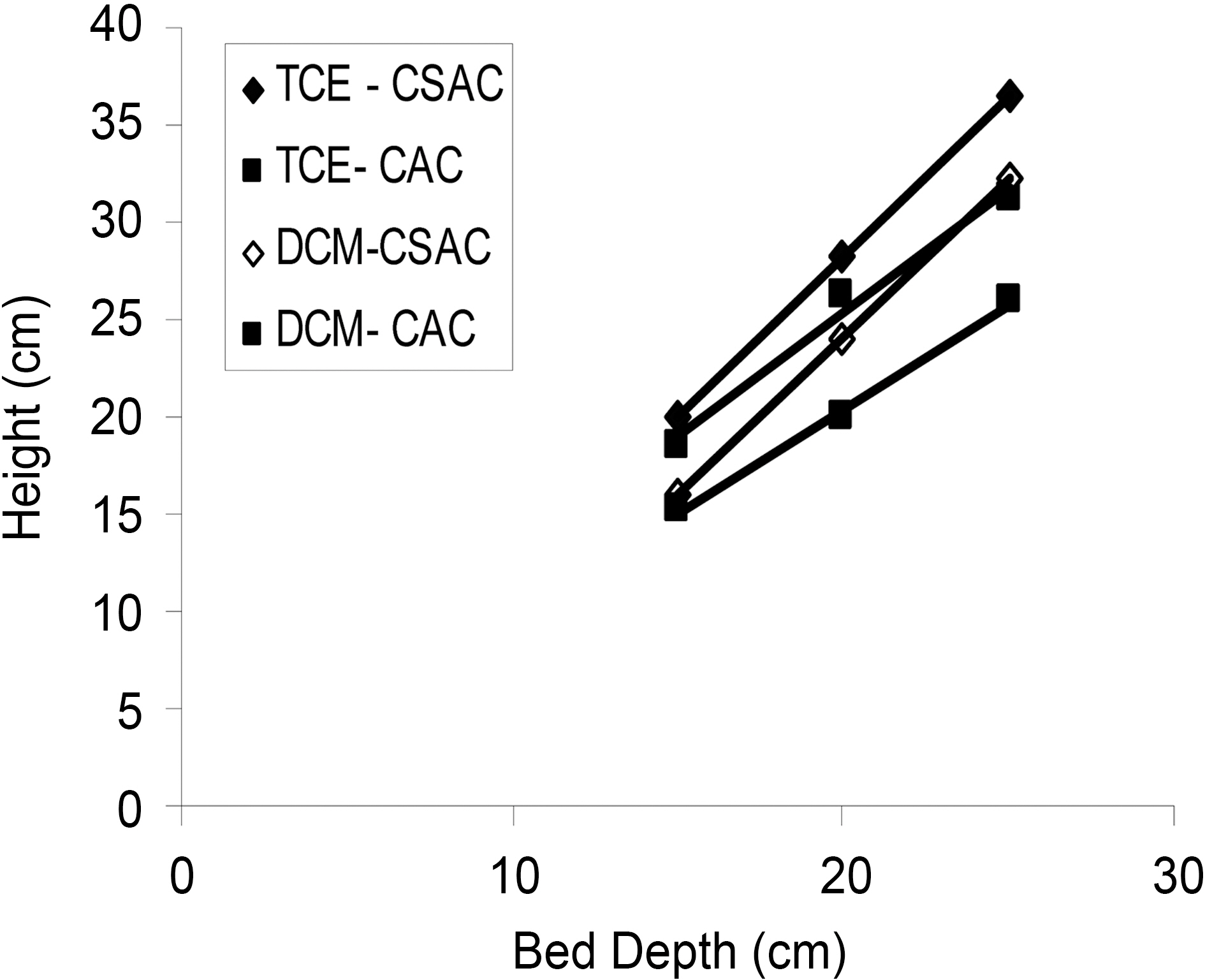
Iso?removal lines were plotted for linear flow rate of 5 mL/min for the three different bed heights with an influent concentration of 200 mg/L. The plot of service time against bed height was linear for both the compounds using both the activated carbons (Fig. 3) indicating the validity of the BDST model for the present systems. The breakthrough time at desired breakthrough concentrations exhibit linearity with bed depth. From the slope (
The sorption capacity of bed per unit bed volume N0 and ka the rate constant were calculated from the equation (9) and the N0 values were found to be 20034.24, 19789.92 mg/L for TCE and DCM using CSAC and 15820.80, 13193.28 mg/L using CAC respectively. The rate constant was calculated as 0.0057, 0.0030 using CSAC and 0.0852, 0.0216 using CAC for TCE and DCM respectively.
Good correlation prediction was found for the case of changed feed concentration and flow rate. Thus, developed model and the constants evaluated could be employed for the design of adsorption columns over a range of feasible flow rates and concentrations.
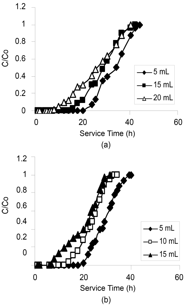
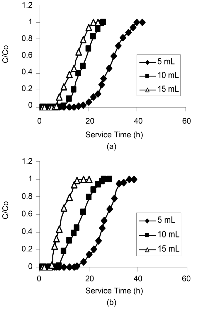
The plots of effluents chlorinated organic concentration versus time at different flow rates are shown in the Fig. 4 and 5. It is evident from the figures that as the flow rate increased, the service times were shortened and therefore the volume treated. In addition, decreasing flow rate resulted not only in the breakthrough time increasing but also in the breakthrough curve broadening, which in turn resulted in an increase in the difference between the breakthrough time and
the saturation time as observed during the adsorption of phenols using Pinus Pinaster bark packed bed [19].
As the flow rate increased the break through curve became steeper, which was also resembled by the slope of the Scurve.According to Aksu et al. [12] increasing flow rate in column operations resulted in loss of sorption capacity. The reason for this behavior could explain in two ways:
-When the flow rate increases, the residence time of the solute in the column decreases, which causes the organic solute to leave the column before the equilibrium occurs.
-When the process is intra-particle mass transfer controlled, a slower flow rate favors the sorption and when the process is subjected to external mass transfer control, a higher flow rate decreases the film resistance [21]. Also the lowest flow rate (5 mL/min) displayed a relatively high removal of all the compounds.
The breakthrough data obtained by varying the flow rate were fitted using the Thomas model equation (10) the
constants derived from the equation kTh and Q0 along with the correlation coefficients obtained are given in the Table 3.High correlation coefficients for all the chlorinated organic compounds using CSAC and CAC were observed. The adsorption capacity of TCE was higher than DCM.
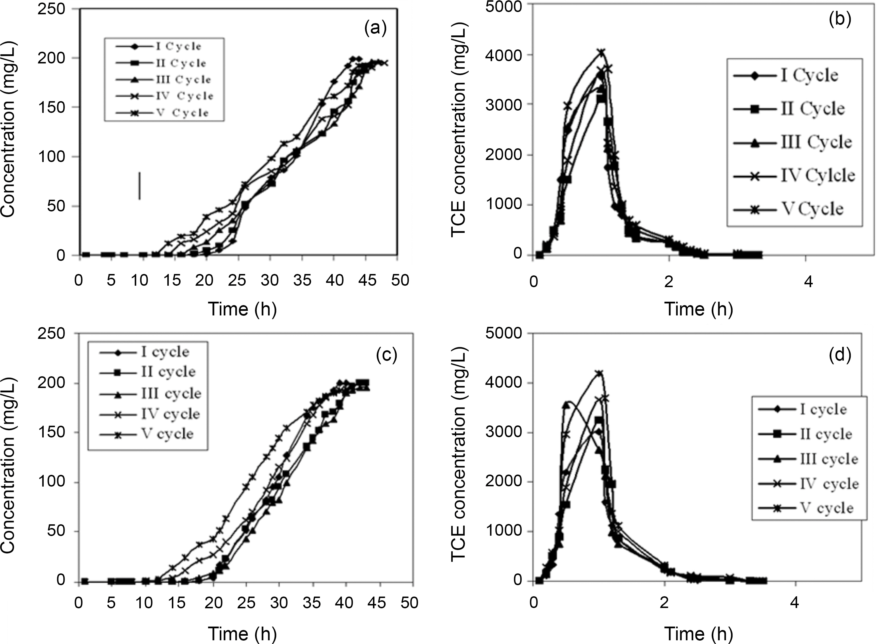
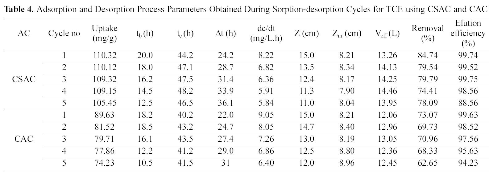
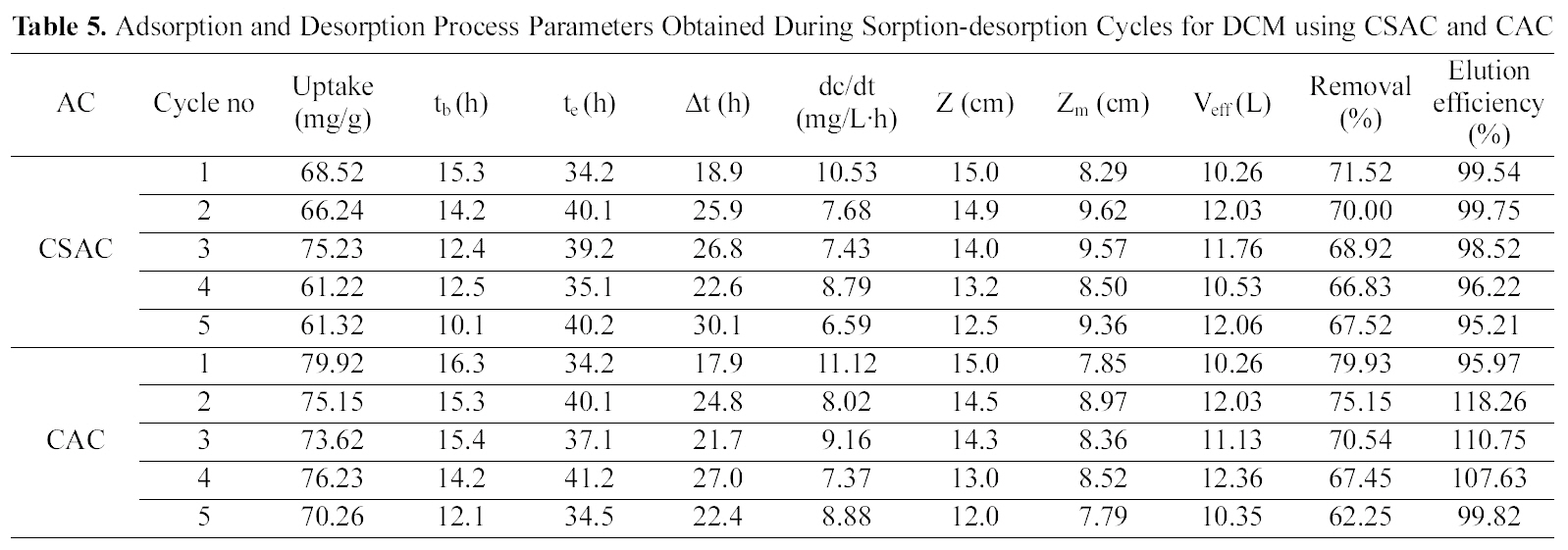
The column was packed with an average amount of 22 g of CSAC and 24 g of CAC yielding an initial bed height of 15 cm and bed volume of 63.59 mL with a packing density of 345.96 g/L for CSAC and 377.41 g/L for CAC for adsorption of both the chlorinated organic compounds.Regeneration of the activated carbon was carried out using suitable solvent (25% isopropyl). Table 4 and 5 reveal the crucial bed height, % removal, elution efficiency and TCE and DCM uptake for the five cycles.
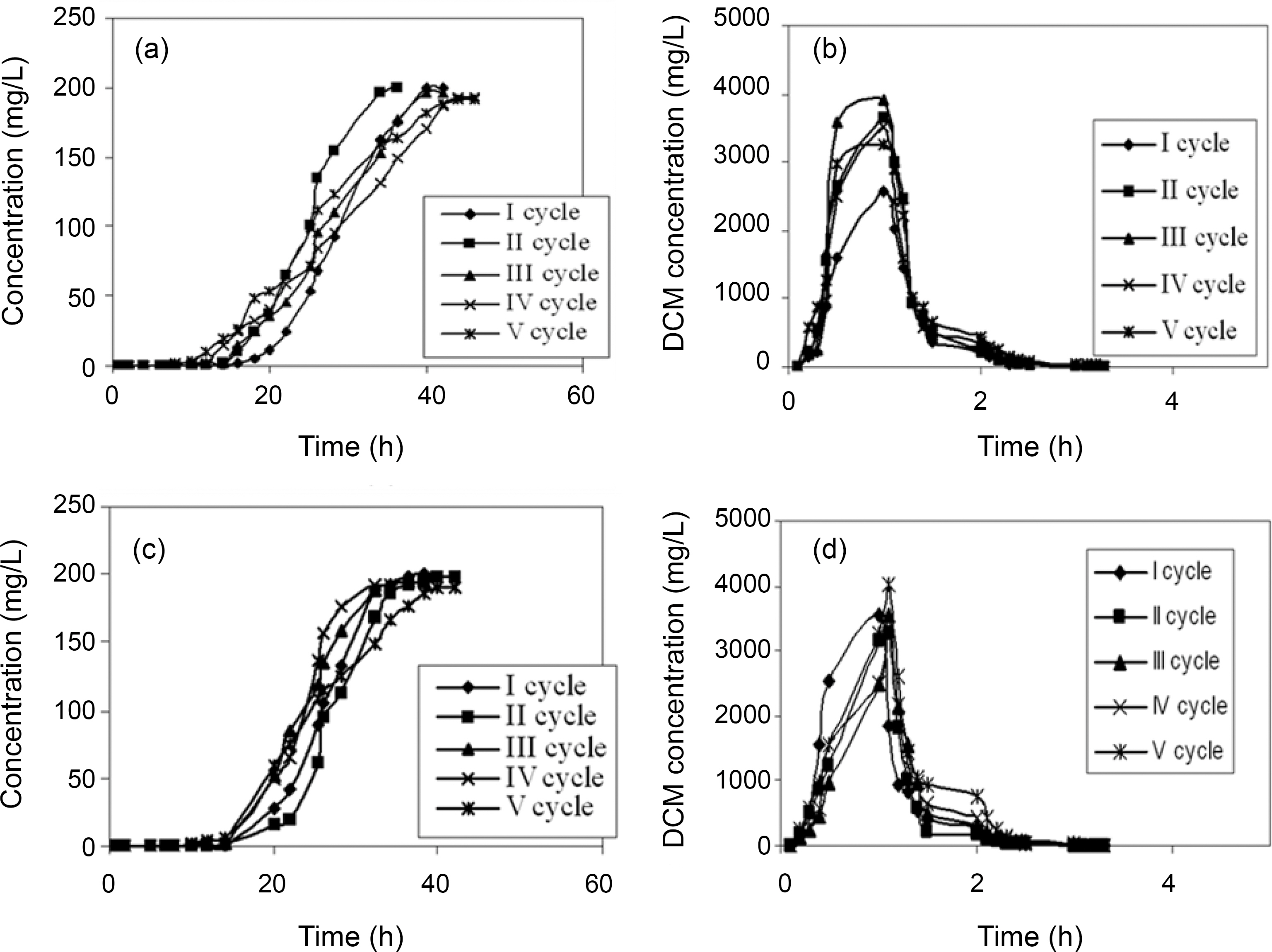
With the regeneration cycles there was a decrease in the
Adsorption and Desorption Process Parameters Obtained During Sorption-desorption Cycles for TCE using CSAC and CAC
Adsorption and Desorption Process Parameters Obtained During Sorption-desorption Cycles for DCM using CSAC and CAC
breakthrough time and an increase in the exhaustion time for all the five compounds. The bed exhaustive limit was selected as 199 mg/L for all the two chlorinated organic compounds, in order to avoid the time delay that normally occurs for full bed saturation. The overall sorption zone (Δt)tended to increase as the cycle progresses, indicating that the sorption sites were not easily accessible as they were still occupied by the compounds or destroyed by previous elution. The breakthrough and the elution curve for the TCE and DCM are represented in the Figs. 6 and 7. The break through curves tend to become flattened as the cycles proceeded, which was also represented by the slope of length actually decreased after five sorption-desorption cycles. The bed height after five sorption- desorption cycles was dropped to 11.1 and 11.7 cm using CSAC, 12 and 11.3 cm for CAC for TCE and DCM, whereas bed volume and packing density decreased to 43.29 and 47.05; 50.87 and 47.90, mL; 221.76 and 246.93; 251.65 g/L; 267.38 and 259.51 g/L for CSAC and CAC for TCE and DCM respectively.
The elution curves observed for both TCE and DCM in all the cycles followed a similar trend; there was a fast increase in the beginning and then a gradual decrease. The flow rate of the elution curve was maintained at 10 mL/min in order to avoid the over contact of the eluant with the carbon and also to obtain maximum concentration in a shorter time [13]. The values obtained from the sorption and the elution curves for both the compounds are presented in Table 4 and 5. The uptake capacity and the removal (%) for all the compounds invariably of the activated carbon used decreased with the increase in the cycles. The elution process was completed within 4 h of time for both the compounds with both the activated carbon thus obtaining maximum elution capacity in a shorter time.
The critical bed length also uniformly increased as the cycle progressed, which indicated the broadening of mass transfer zone [21]. The life factor based on critical bed length can be calculated from the following equation.

From the plot of Zm Vs x (graph not shown), Zm,0 and KL were found to be 8.33 and 9.99; 0.061 and 0.063 cm/cycle;8.10 and 6.78 cm and 0.136 and 0.039 cm/cycle using CSAC and CAC for TCE and DCM respectively.
The present work was an attempt to access the effect of various parameters like bed depth, flow rate on break through time and adsorption capacity of TCE and DCM using CSAC and CAC. In all the cases the lowest flow rate(5 mL/min) and the highest bed height (25 cm) resulted in maximum uptake and per cent removal. Regeneration carried out using 25% isopropyl alcohol was also found to be highly satisfactory. This study has helped to ascertain the practical applicability of the adsorbent. The models have provided an objective framework for the interpretation of the adsorption system and to obtain the scaling up and designing of adsorption process at the pilot scale. Also, this study indicates that the CSAC is much more effective compared to CAC.
℃ Degree Celsius
h hour
% Percentage
mg milligram
mL milliliter
mm millimeter
㎛ micrometer
Δt Mass transfer zone (h)
ν linear velocity (cm/h)
Abbreviations
AOX Adsorbable Organic Halogens
C0 Initial organic halide concentration (mg/l)
CAC Commercial activated carbon
Cf Equilibrium organic halide concentration (mg/l)
CPAC Coir pith activated carbon
CSAC Coconut shell activated carbon (50% KOH activated)
dc/dt Slope of the breakthrough curve from tb to te (mg/l h)
DCM Dichloromethane
E Elution efficiency (%)
F Flow rate (ml/min)
Ka BDST model constant (L/mg h)
kL Life-factor (cm/cycle)
kTHThomas model constant (l/mg h)
m Sorbent mass (g)
Mad Mass adsorbed (mg)
Mtotal Mass desorbed (mg)
N0 Sorption capacity of the bed (mg/l)
Qo Maximum solid phase concentration of solute (mg/g)
t Time (h)
tb Breakthrough time (h)
TCE Trichloroethylene
te Exhaustion time (h)
V Solution volume (l)
Veff Effluent volume (l)
x Number of cycles
Z Bed depth (cm)
Zm Critical bed length (cm)
Zm0 Initial critical bed length (cm)