White organic light emitting-devices (WOLEDs) have attracted much attention in the past decade because they show promise in realizing high resolution full color displays and solid state lighting applications [1,2]. In particular, WOLEDs based on polymer host layers have been extensively studied because they can provide low-cost, large area applications using simple processes,such as spin coating and inkjet printing [3,4].
Poly(N-vinylcarbazole) (PVK) has been widely used as a host material for polymer WOLEDs because it has an excellent filmforming property and a high glass transition temperature [5,6]. In addition, PVK has a high triplet energy of about 2.5-3.0 eV so that it can be used as a host material for phosphorescent emitters, which can form highly efficient white devices by harvesting both the electro-generated singlet and triplet excitons [7-9]. For example, Kawamura et al. [6] reported on spin coated PVK based WOLEDs with an external quantum efficiency of 2.1% by doping blue, yellow, and red phosphorescent emitters. However, the quantum efficiency of their device was low compared to vacuum evaporated phosphorescent WOLEDs [10]. Since PVK has a holetransporting property, an electron-transporting material is required in order to balance the electrons and holes. The charge balance in a PVK-based device can be enhanced by adding electron-transporting materials into the host and/or by depositing additional electron-transport layers onto the host. For example, Wu et al. [11] mixed l,3-bis[(4-tert-butylphenyl)-l,3,4-oxadiazolyl] phenylene (OXD-7) into the PVK host. As an example of the deposition method, Kawamura et al. [6] used 2,9-dimethyl-4,7 diphenyl-1, 10-phenanthroline (BCP) /tris-(8-hydroxyquinoline) aluminum (Alq3) double layers deposited onto the PVK host.
In this paper, we report upon WOLEDs using a PVK host layer doped with blue, green, and red phosphorescent emitters. Iridium (III) bis [(4,6-difluorophenyl)-pyridinato-N,C2']picolinate (FIrpic), tris (2-phenylpyridine) iridium(III) [Ir(ppy)3], and tris (2-phenyl-1-quinoline) iridium (III) [Ir(phq)3] were used as the blue, green, and red phosphorescent guest materials for the PVK-based WOLEDs, respectively [12-14]. Although the Ir(phq)3 has been known to be a highly efficient and stable red phosphor[12], it has not been used as a guest material for a polymer-based white device. We are the first to introduce Ir(phq)3 to be used as a red phosphor for a PVK-based WOLED. Since the Ir(phq)3 has a high phosphorescence efficiency and a small band gap, it can be proper guest material for a white emission [12]. We used
3-(4-biphenylyl)-4-phenyl-5-(4-tert-butylphenyl)-1,2,4-triazole (TAZ) for an electron transport layer on the doped PVK layer. By using the doped PVK/TAZ bilayer structure, we created simply structured, high efficiency white devices. We also investigated the carrier recombination on the guest materials and the energy transfer between the guest materials in these PVK-based WOLEDs.
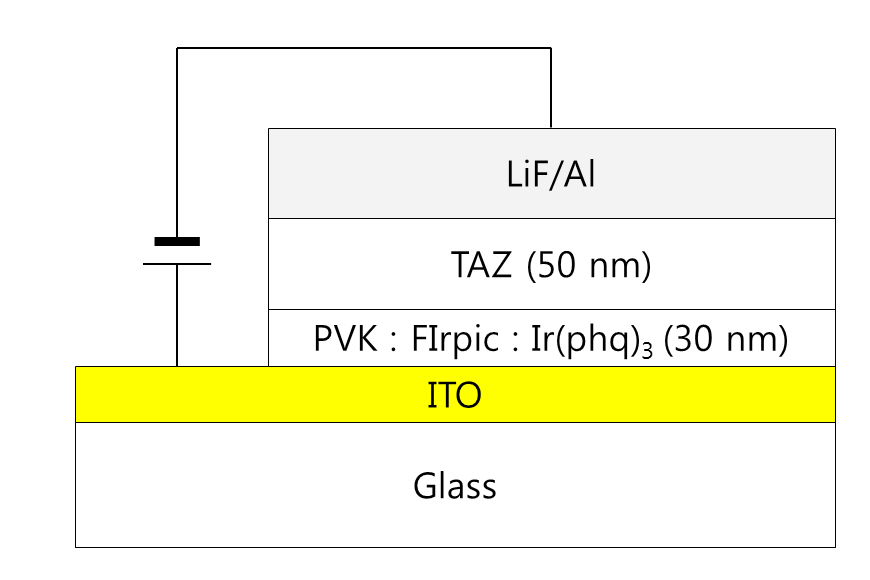
Indium tin oxide (ITO) coated glass substrates were used for the preparation of the PVK-based WOLEDs. The sheet resistance of the ITO film was about 10 Ω/sq. After defining the ITO anode patterns by using a standard photolithography process, the substrates were cleaned with isopropyl alcohol and deionized water. The cleaned substrates were treated using oxygen plasma at 100 W before spin-coating the doped PVK solutions prepared by mixing the blue, green, and red phosphorescent materials with the PVK in a chlorobenzene solution. Ir(phq)3 and FIrpic were used as the red and blue dopants, respectively, in the two wavelength WOLEDs. The concentration of FIrpic was fixed at 8%in the PVK host, whereas the Ir(phq)3 was varied from 1% to 8%.For the three wavelength WOLEDs, an additional 1% green phosphorescent emitter, Ir(ppy)3, was doped into the PVK host. The thickness of the doped PVK layer was 30 nm. After the preparation of the doped PVK emission layer, a 50 nm thick TAZ electron transport layer was deposited by using a vacuum evaporation method at a base pressure of about 1 × 10⁻⁶Torr. A 0.5 nm thick LiF and a100 nm thick Al layer were sequentially evaporated through a shadow mask without breaking the vacuum. The completed device structure was ITO/PVK (30 nm):FIrpic (1%):Ir(ppy)3(1%):Ir(phq)3 (1-8%)/TAZ (50 nm)/LiF (0.5 nm)/Al (100 nm). Figure 1 shows the schematic diagram of the completed device. The active area of the device was 4 × 4 mm2. The current densityvoltage-luminance ( J-V-L) characteristics of the devices were measured using a computer controlled Keithley 2400 sourcemeasure unit and a calibrated fast Si photodiode (FDS 100). The electroluminescence (EL) and the photoluminescence (PL) spectra were measured with a spectroradiometer (Minolta CS1000).
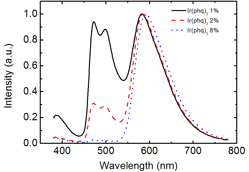
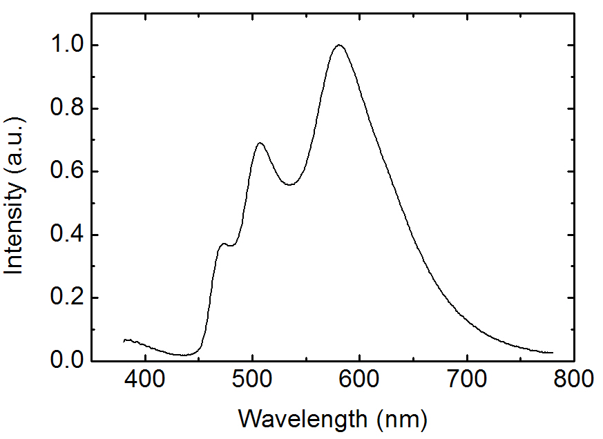
Figure 2 shows the EL spectra for the OLEDs doped with FIrpic and Ir(phq)3 into the PVK host. The blue phosphorescent guest molecule, FIrpic, was fixed at 8%, whereas the concentration of the orange-red phosphorescent dopant, Ir(phq)3 was varied over 1-8%. After mixing the FIrpic, Ir(phq)3, and PVK materials into the chlorobenzene solution, the doped PVK solution was
spin-coated to form the emission layer. The device structure was ITO/PVK (30 nm):FIrpic (8%):Ir(phq)3 (1-8%)/TAZ (50 nm)/LiF/Al. In the EL spectra, the emission peaks at 470 nm and 500 nm are ascribed to the emissions from the metal to ligand charge transfer and the π-π* transitions, respectively, for the FIrpic guest molecules [3], whereas the red emission peak at 580-590 nm corresponds to the triplet emission from the Ir(phq)3 molecules [15]. As shown in Fig. 2, the blue peak intensity originating from FIrpic decreases with an increasing Ir(phq)3 concentration. For example,at the 1% Ir(phq)3 concentration, the peak intensity of the FIrpic emission is almost same as that of the Ir(phq)3 emission. However, the FIrpic peak almost disappears at an 8% Ir(phq)3 concentration. Therefore, a white emission can be achieved by doping a low concentration of Ir(phq)3 guest molecules into the PVK host. The decrease of the FIrpic emission at a high Ir(phq)3 concentration may be attributed to the energy transfer of the triplet excitons from the FIrpic to the Ir(phq)3 molecules, since the triplet energy level of Ir(phq)3 (2.13 eV) [15] is lower than that of FIrpic (2.62 eV) [14]. At a low Ir(phq)3 concentration, the FIrpic and the Ir(phq)3 molecules are sufficiently separated for an incomplete energy transfer from the FIrpic to the Ir(phq)3 to occur, resulting in a relatively high FIrpic emission intensity. The energy transfer from the high triplet energy FIrpic to the low triplet energy Ir(phq)3 is accelerated by a decreased distance between the Firpic and the Ir(phq)3 molecules at a high Ir(phq)3 concentration. It should be noted that the strong red emission intensity at the high Ir(phq)3 concentration may also be attributed to the increased direct recombination of the Ir(phq)3 mol-
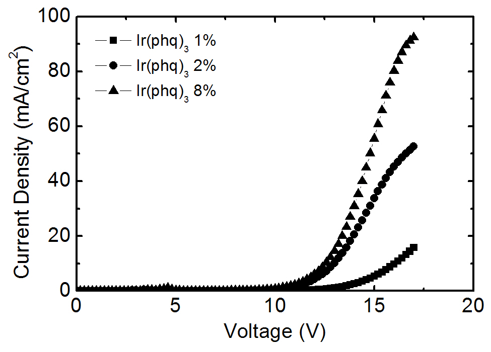
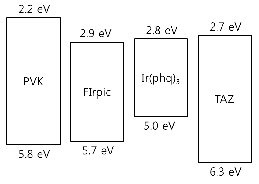
ecules [16-18], as shown in the current density-voltage curves in Fig. 3. The required applied voltage needed to obtain the same current density is higher at a low Ir(phq)3 concentration. For example, an applied voltage of 16.0 V is required to obtain a current density of 10 mA/cm2 at the 1% Ir(phq)3 concentration. However, the 8% Ir(phq)3 device needs a voltage of 12.6 V in order to obtain the same current density. It indicates that the carriers are directly injected into the Ir(phq)3 molecules and so the current flows by hopping between the Ir(phq)3 molecules [16-18]. Hence, the carriers are directly recombined on the Ir(phq)3 molecules. This is energetically preferable, since the highest occupied molecular orbital (HOMO) and the lowest unoccupied molecular orbital (LUMO) energy levels for Ir(phq)3 are located inside the band gap of the PVK host[19,20], as shown in Fig. 4. The HOMO and LUMO energy levels of Ir(phq)3 are 5.0 and 2.8 eV, respectively[19]. On the other hand, PVK has the HOMO and LUMO energy levels of 5.8 and 2.2 eV, respectively [20]. Therefore, the energy barrier for the hole injection from the ITO into the PVK is 0.8 eV higher than that found for the hole injection from the ITO into the Ir(phq)3, resulting in the holes being directly injected into the Ir(phq)3 molecules. Electrons can also be directly injected into the Ir(phq)3 from the TAZ, since the LUMO level difference between the Ir(phq)3 and the TAZ is small (0.1 eV). Therefore, it can be concluded that both the energy transfer and the direct excitation contribute to the high intensity of the red emission
at the high Ir(phq)3 concentration. In addition, the red emission peak in the EL spectra seen in Fig. 2 is slightly shifted to a longer wavelength at the high Ir(phq)3 concentration, due to the solid state solvation effect [21]. Another feature seen in the EL spectra from Fig. 2 is the emission peak at about 390 nm. This emission intensity is high at the low Ir(phq)3 concentration. The intensity at 390 nm is about 20% compared to the Ir(phq)3 peak at the 1%Ir(phq)3 concentration. The emission at 390 nm is attributed to the fluorescence from the TAZ layer, which was confirmed by comparing the PL emissions of the PVK and the TAZ. The PVK exhibits its PL emission at about 420 nm, whereas the TAZ shows its PL peak at about 390 nm. The emission from the TAZ layer is attributed to the holes that pass into the TAZ layer without recombination inside the doped PVK layer. More holes are passed into the TAZ layer in the 1% Ir(phq)3 device, since the holes on the Ir(phq)3 molecules are saturated as a result of the small number of Ir(phq)3 sites.
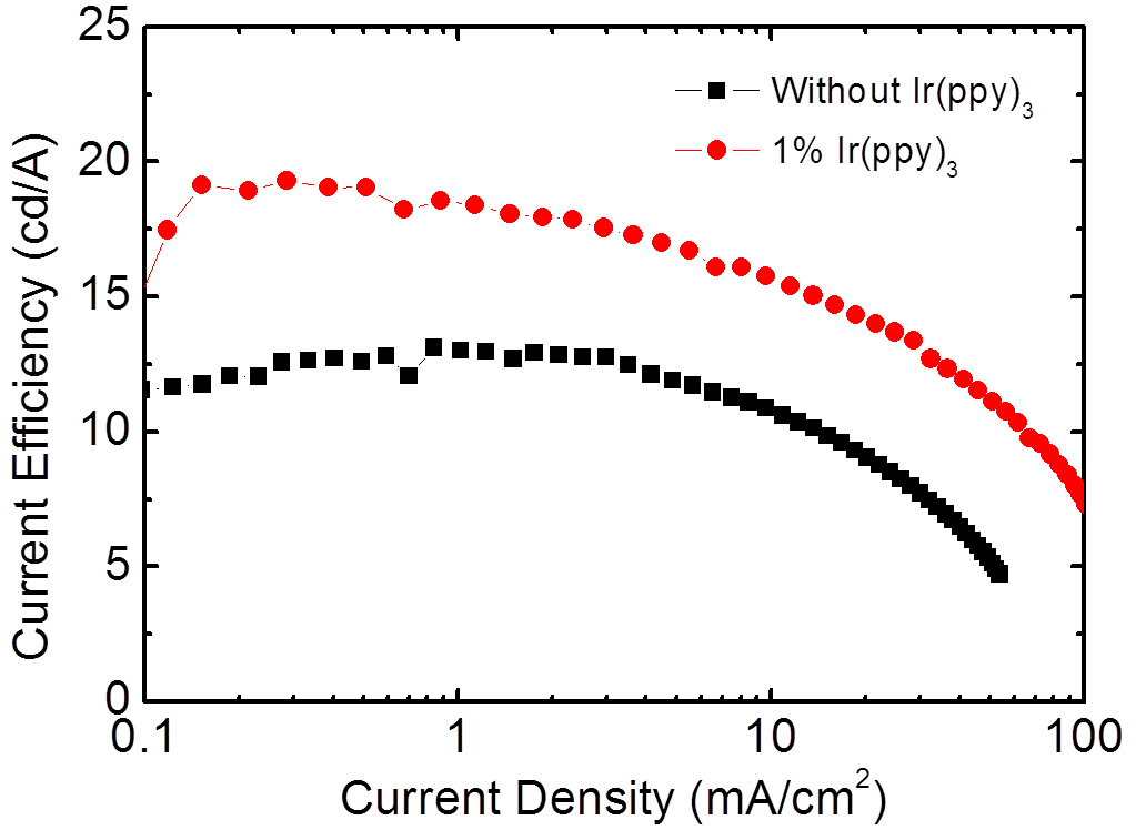
Figure 5 shows the EL spectrum for the three wavelength WOLEDs doped with FIrpic, Ir(ppy)3, and Ir(phq)3 into the PVK host. The concentrations of the FIrpic, Ir(ppy)3, and Ir(phq)3 were 8%, 1%, and 1%, respectively. When the spectrum is compared to that of Fig. 2, the blue emission intensity decreases by adding the 1% Ir(ppy)3 guest molecules, which is accompanied by an increase in the green emission at 510 nm due to the phosphorescent decay from the Ir(ppy)3 molecules. This decrease of the blue emission intensity can be attributed to the energy transfer from the FIrpic to the Ir(ppy)3 molecules, since the triplet energy level (2.62 eV) of the FIrpic [14] is higher than that found in Ir(ppy)3 (2.41 eV) [22]. Another feature in the spectrum seen in Fig. 5 is the decreased fluorescent emission from the TAZ layer, which indicates that more recombination takes place in the doped PVK layer. This energy transfer to the Ir(ppy)3 molecules and the suppressed passing of holes into the TAZ layer result in an improvement of the EL efficiency, as shown in Fig. 6. The three wavelength WOLED incorporating the Ir(ppy)3 exhibits a maximum current efficiency of 19.2 cd/A, whereas the equivalent two wavelength device without the Ir(ppy)3 shows a maximum efficiency of 13.1 cd/A. Therefore, a high efficiency three wavelength WOLED can be created by doping FIrpic, Ir(ppy)3, and Ir(phq)3 phosphorescent guest molecules into the polymer host PVK.
Phosphorescent WOLEDs have been fabricated using a spincoated PVK host layer doped with FIrpic, Ir(ppy)3, Ir(phq)3 phosphorescent emitters. The WOLEDs have a simple bilayer structure of ITO/doped PVK/TAZ/LiF/Al. In the two wavelength devices, composed of FIrpic and Ir(phq)3, as the red phosphorescent Ir(phq)3 concentration increased, the blue emission intensity decreased, due to both the enhanced energy transfer from the high triplet energy FIrpic to the lower triplet energy Ir(phq)3 and the increased direct recombination of the Ir(phq)3 molecules. The maximum current efficiency of the three wavelength WOLEDs was 19.2 cd/A. The current efficiency of the WOLEDs increases by the Ir(ppy)3 doping, caused by both the increased energy transfer from the FIrpic to the Ir(ppy)3 and the suppressed fluorescent recombination in the TAZ layer.