Satellite laser ranging (SLR) system measures the round trip flight time of ultra-short laser pulses to satellites to provide the information of the distance to satellites and it is the most accurate system among the systems determining orbits of satellites currently available. SLR technology was firstly applied by National Aeronautics and Space Administration (NASA) in 1964 to determine the orbit of the satellite, Beacon Explorer-B, to which a laser reflector was installed, and the precision of the distance measurement was at a meter level at that time. However, as it can now provide the precision level of several millimeters thanks to the development of optical and electronic technologies, it is applied in various researches including geodesy, geophysics and resources exploration (Degnan 1994). Currently, there are about 40 SLR observatories in the world and about 30 satellites that have laser retro-reflector array (LRA) are in operation including high-precision geodetic satellites. Since Galileo and Compass navigational satellites will be equipped with LRA for high-precision geodetic service in the future and the SLR system will be also applied to planet exploration (Neumann et al. 2006, Smith et al. 2006) as well as lunar probes (Zuber et al. 2010), the international demand for SLR is gradually increasing.
In Korea, KASI has developed mobile and stationary SLR systems since 2008 in order to secure the technologies for the space geodetic study, the precise distance measurement of millimeter level and the high-precision orbit determination through the laser tracking of the satellites with LRA. The mobile SLR system (ARGO-M), which will be completely developed in 2011, is the separate optical path type that employs a 40 cm-receiving telescope and the laser with the repetition rate of KHz. In addition, it is equipped with an event timer as the time measurement equipment that can measure the KHz laser, the compensated single photon avalanche diode (C-SPAD) detector that calibrates the time-walk error, and the spatial and band-pass filters for daylight tracking. In particular, it allows observation in different location because it is established in a container structure. It provides precise tracking and high pointing capabilities because the telescope, the tracking mount and the laser system are designed to block vibrations coming from the container during observation. The stationary SLR system (ARGO-F), which is equipped with a telescope of 1 m diameter, has the common optical path and its development will begin after completing ARGO-M.
The number of return photons from satellites in laser ranging is dependent on the system specifications, the characteristics of the laser reflector installed to the satellite, the distance to the satellite and the atmospheric environment, and the effect of the distance to the satellite is the strongest among these factors. In general, SLR system shoots approximately 1015-16 photons through the transmission telescope, but the number of photons that can be detected by an actual receiving optical system ranges from one to hundreds. In the case of daytime observation, different from night observation, it is very hard to actually distinguish the return signals reflected by the satellite by just one shot of laser pulse from the surrounding background noises. Thus, to increase the probability to distinguish the actual signals from the noises, various factors should be considered in the design including the link budget, signal characteristics and the precision of the orbit prediction.
In this study, we analyzed the link budget to calculate the number of photons received by ARGO-M while the night tracking and daylight tracking of STSAT-2B and KOMPSAT-5. In addition, for the daylight tracking, the false alarm probability by the background noises was investigated depending on the band-pass width of the spectrum filter and the range gate (RG) of the time filter, and the signal detection probability that means the probability to distinguish the actual signals from the background noises was analyzed and compared for STSAT-2B and KOMPSAT-5. We also investigated the limiting conditions of the signal characteristics and orbit prediction precision in determining the optimal specifications of the spectrum filter and time filter to elevate the performance of the ARGO-M system.
ARGO-M is composed of five sub-systems that are the optical system, the photoelectronic part, laser system tracking mount and operating system. The optical system shoots laser pulse to satellites and collects the reflected optical signals. The photoelectronic part detects the optical signals and precisely measures the time of flight of the laser pulse at the pico-second level. The laser system generates the ultra-shot laser pulse of 532 nm wavelength and the tracking mount is the mechanical system that performs precise tracking of satellites, supporting the optical telescopes and the peripheral devices. The operating system controls various sub-systems needed for the laser observation, performs actual observation after comprehensively judging the observation environment and reflecting the results, and integrates, processes and transmits the data obtained by the actual observation.
ARGO-M is designed to measure the distance to the satellites whose altitude is 300∼25,000 km with laser and have the precision less than 10 mm for the single shot of LAGEOS satellite and 5 mm for the normal point data. The major functions include that it allows night and daylight tracking by using the laser pulse of KHz-level repetition rate, it has the laser hazard reduction system that prevents the damage of the aircraft pilots by laser , it can perform automatic observation scheduling by the interlocking with the meteorological equipments, and it can be operated by remote control.
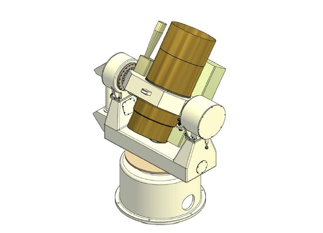
As shown in Fig. 1, the transmitting and receiving path in the ARGO-M system is separate so as to operate the KHz laser pulse and the diameters of the receiving telescope and transmitting telescope are 400 mm and 100 mm, respectively, considering the mobile observation. Since the tracking mount should be rapidly moved for the tracking of the low earth orbit satellites, different from the tracking of celestial bodies, the main mirror of receiving telescope is designed to have the F number (focal length to aperture ratio) of 1.5. Because the spreading area of the laser beam varies depending on the altitude,
the transmitting telescope that is composed of two lenses for the laser tracking of the high and low earth orbit satellites has the function to control the divergence angle of the laser beam. Photo diodes are installed inside the laser oscillator to detect the transmitted photons so as to measure the laser shooting time and the return photons reflected by the satellites are detected by C-SPAD (PESO Consulting, Praha, Czech Republic). Although SPAD with short rising time is appropriate to the laser system with high repetition rate, there is time-walk error in which the rising time is changed by both light pulse energy and the temperature of the device. Thus, C-SPAD has the function to calibrate such an error. Different from C-SPAD, mircochannel plate-photo multiplier tube detector is free of the time-walk error, but the signal jitter is relatively large. The electric pulse signals from the detector is sent to the device that measures the time of flight of the laser pulses by receiving 1 PPS and 10 MHz signals from the global positioning system (GPS) receiver. The time measurement devices applied in SLR system include the event timer and time interval counter, but the ARGO-M system employs the event timer that allows laser ranging of high repetition rate. The RG of the C-SPAD should be opened and closed by predicting the arrival time of the photons returning from the satellites and a rapid RG performance is required especially for the SLR system with the high repetition rate laser. In the case of ARGO-M, field programmable gate array (FPGA) carries out the function. In addition, FPGA generates the laser shooting
[Table 1] Major specification of ARGO-M.
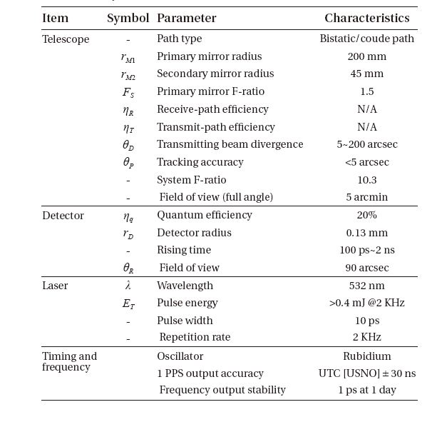
Major specification of ARGO-M.
signals and shifts the laser shooting times to avoid the interference of the arriving photons from the shooting laser by expecting photon-arriving time. The precision and resolution of the RG generation by FPGA are less than 5 ns and 2 ns, respectively. Table 1 shows the performance and specifications of ARGO-M determined after the preliminary design review.
Since it is very difficult to distinguish actual signals from background noise in daylight tracking, different from night tracking, three filters?spatial filter, spectrum filter and time filter?are used to make it possible. Generally, field of view (FoV) of spatial filter is designed to be a little larger than the divergence angle of the transmitting beam and the band-pass width of the spectrum filter is determined by considering the pulse width of the laser and Doppler effect (Degnan 1993). The time filter is used to eliminate noise using RG width which is 0.1 μs-1 μs in the case of LAGEOS. For low earth orbit satellites, which undergo atmospheric perturbation and frequent orbital maneuvering, should have larger RG width since the orbit prediction precision is low (Degnan 1993). In the case of ARGO-M, the variable iris at the primary focus plays the role of spatial filter with several pinholes and it also plays the role of solar shutter that protects the detector from the sun light. The spectrum filter is located in between C-SPAD and the reducing optics, and the RG width command is delivered to C-SPAD. The RG width can be chosen between 1 ns-100 μs, but the FPGA of ARGO-M sends the command of a fixed RG width to C-SPAD.
3. LINK BUDGET AND DAYLIGHT TRACKING OF ARGO-M
The number of return photons of laser pulses shot by the ARGO-M system and reflected by LRA of STSAT-2B and KOMPSAT-5 is dependent on the system hardware specifications, the distance to the satellite, the characteristics of the laser retro-reflector installed to the satellites, and the atmospheric transmittance. The average number of photons measured by the ARGO-M detector is calculated by following radar link equation (Degnan 1993):
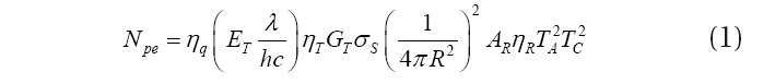
where Npe denotes the average number of photons that can be detected from a single laser shot, ηq the quantum efficiency of the detector, ET the laser pulse energy, λ the
wavelength of the laser,
The transmitter gain is the parameter related with how much of the laser energy from the transmitting telescope reaches the satellite. Because all the SLR systems use the pulse laser with gaussian spatial and temporal profiles, the transmitter gain with respect to the Gaussian beam can be calculated with the following equation (Degnan 1993):
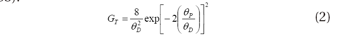
where θD denotes the far field divergence half-angle of the transmitted beam and θp denotes the beam pointing error.
Since Cassegrain or Ritchey-Chretien focusing method is usually applied to the SLR receiving telescope, the secondary mirror blocks the received light while receiving the laser. Thus, the effective area of the primary mirror where the photons can be actually received is calculated by the following equation (Degnan & Klein 1974):
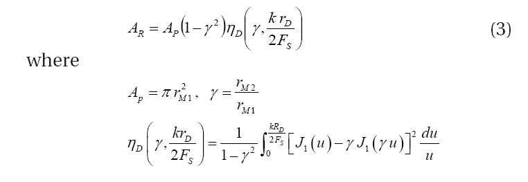
Here, AP denotes the effective receiving area of the primary mirror, γ the ratio of the primary mirror area blocked by the secondary mirror, ηD the fraction of incoming photons that are implanted to the detector area at the focal plane, rD the radius of the detector, FS the F-number of the primary mirror and J1 the Bessel function of the first kind, and k is defined as k = 2π/λ. Since, the detector area is designed to have an area enough to detect all the photons from the focal plane in an actual SLR system, ηD ? 1.
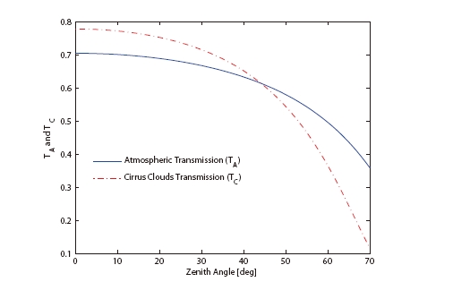
It is known that the atmospheric attenuation of the visible light of 0.3-0.7 μm wavelength and near UV range is mainly dominated by the aerosol scattering, absorption by atmospheric molecules and ozone. It is also known that the probability that sub-visible cirrus may exist in the sky where most of the part is clear is about 50 % of a certain period and the mean thickness of cirrus over the entire earth is 1.341 km (Hall et al. 1983). The transmittance by the atmospheric attenuation and cirrus is expressed as the following equation (Degnan 1993):
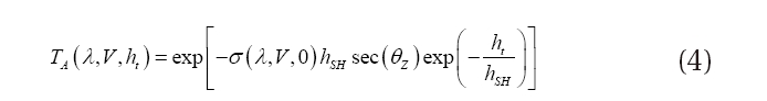
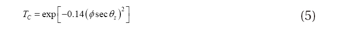
σ(λ,V,0), which is the atmospheric attenuation coefficient at sea level, depends on the atmospheric conditions and the laser wavelength. Its value of 532 nm wavelength laser is about 0.25 on a clear day (V=15 km). V denotes the visibility at sea level, θZ the zenith angle and
As can be known from Eq. (1), the link budget is affectedthe most by the distance between the observatory and the satellite. Given the altitude of the satellite above sea level and the zenith angle of the satellite from the SLR observatory, the distance can be calculated by the followingequation (Degnan 1993):
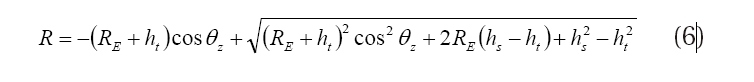
where
In the case of daylight tracking of a satellite with a low link budget, different from night tracking, it is very difficult to distinguish actual signals from the surrounding background noise which is very strong. In general, the intensity of the background noise at 532 nm of wavelength in daytime is about 105 times stronger than that of the night time and thus the daylight tracking with high background noise should be analyzed to verify the tracking performance of ARGO-M. Actually, laser ranging of navigation satellites such as GPS satellites can be done only in night tracking because Npe <<1 due to the high altitude, although the effective area of LRA (GPS: 40 × 106 m2, GLONASS: 360 × 106 m2) is high (Arnold 2003). The performance of distinguishing actual signals from the background noise can be expressed in terms of probability and the average number of photons detected from the background noise by C-SPAD during the RG opening time is calculated by the following equation (Pratt 1967):
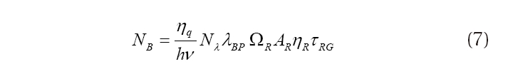
Here,
Since the photon detection follows the Poisson probability distribution (Degnan 1993), the probability of detecting


Because the number of photons detected from the background noise during the response time of C-SPAD is very small, the total number of photons detected during this duration is expressed as Eq. (10) and the photon detection probability,

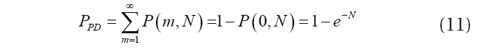
Hence, the signal detection probability,

We analyzed the link budget and daylight tracking performance of the ARGO-M system for the STSAT-2B and KOMPSAT-5 satellites to which LRA are installed for the precise orbit determination.
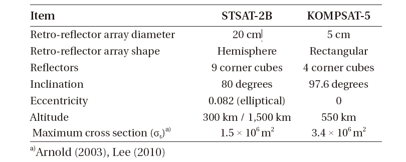
STSAT-2B has the LRA which is the same with that of Shenzhou-4, and KOMPSAT-5 is identical to the CHAMP satellite. The effective area of the LRA is varied depending on the incidence angle of the beam, the speed aberration, the wavelength, and, if the corner cube is not coated, the polarization effect. Thus, the average effective area of LRA is used for the calculation of general link budget. Table 2 shows the characteristics of the orbit and LRA of STSAT-2B and KOMPSAT-5.
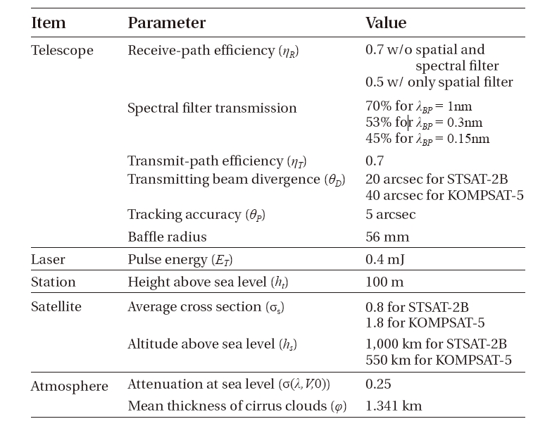
In order to analyze the laser tracking performance of the ARGO-M system for the STSAT-2B and KOMPSAT-5 satellites, the average number of detected photons was calculated under the conditions of the daylight tracking and night tracking, the latitude of the satellites and the spectrum filter with three different band-pass widths (λBP = 1nm,0.3nm,0.15nm). Table 3 shows the parameter values used in the link budget calculation and the efficiency of the receiving optical system in the case where only the spatial filter is used for the daylight and night tracking and in the case where neither the spatial filter nor the spectrum filter is used. Generally, the divergence angle of the transmitting beam is varied depending on the altitude because of the uncertainty of the predicted orbit of satellites. To track STSAT-2B and KOMPSAT5, different divergence angles of the transmitting beam were applied for each of them. In calculating the effective receiving area, the size of baffle was applied instead of the size of the secondary mirror, since the baffle inside the telescope increases the effective receiving area larger than the secondary mirror. The value derived from the CHAMP satellite was used the average effective area of the KOMPSAT-5 LRA and the average value for STSAT-2B.
[Table 2] Characteristics of STSAT-2 and KOMPSAT-2 (http://ilrs.gsfc.nasa).

Characteristics of STSAT-2 and KOMPSAT-2 (http://ilrs.gsfc.nasa).
[Table 3] Parameter values for link budget.

Parameter values for link budget.
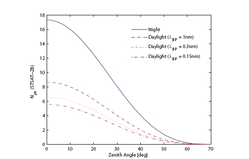
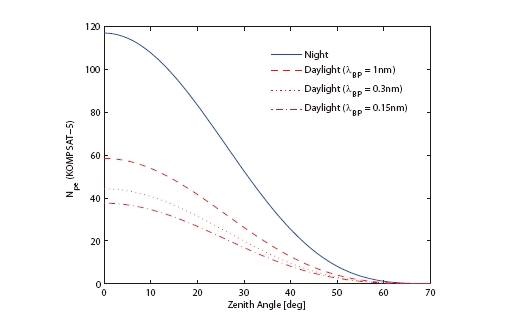
As shown in Table 3, the divergence angles of the transmitting beam are different in tracking STSAT-2B and KOMPSAT-5. Thus, the transmission gains are 7.5 × 10⁸ and 2.1 × 10⁸, respectively, by the Eq. (2) and the effective receiving area of ARGO-M is 0.1158 m2 by the Eq. (3). Figs. 2 and 3 show the average number of photons that can be detected by C-SPAD during the daylight and night tracking of STSAT-2B and KOMPSAT-5. The reason why the number of detected photons is smaller in the daylight tracking than that of night tracking is that the receiving efficiency is decreased by the use of the spectrum filter. As the zenith angle of the STSAT-2B and KOMPSAT- 5 satellites increases, the distance to the satellites also increases and the atmospheric transmittance and cirrus transmittance are decreased, leading to an abrupt reduction of the average number of detected photons. The reason why the average number of detected photons of KOMPSAT-5 is about 7 times larger than that of SATSAT- 2B despite its small transmission gain is based on the distance between the observatory and the satellites and the average effective area of the LRA. Fig. 4 shows the atmospheric transmittance and cirrus transmittance depending on the zenith angle, indicating that the atmospheric transmittance is abruptly decreased than the cirrus transmittance.
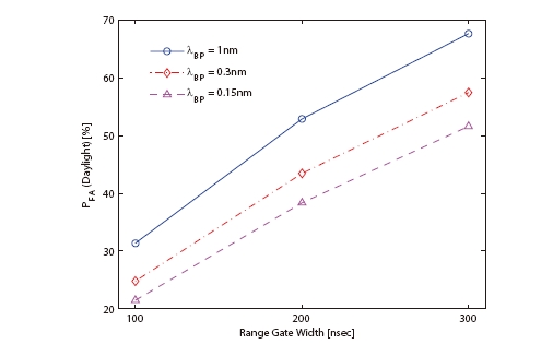
To analyze the daylight tracking performance of the ARGO-M system for STSAT-2B and KOMPSAT-5, the intensity of the daytime background noise was set as Nλ = 0.0146. Different values of τRG, 100, 200 and 300 ns, were applied to analyze the tracking performance depending on the RG width. Fig. 5 shows the false alarm probability of daylight tracking. As τRG and λBP are larger, the false alarm probability is higher. In addition, the false alarm probability is almost zero in the case of night tracking because the intensity of the background noise is much smaller than that of the daylight tracking. Fig. 5 also shows that the false alarm probability is more sensitive to the RG width than to the band-pass width.
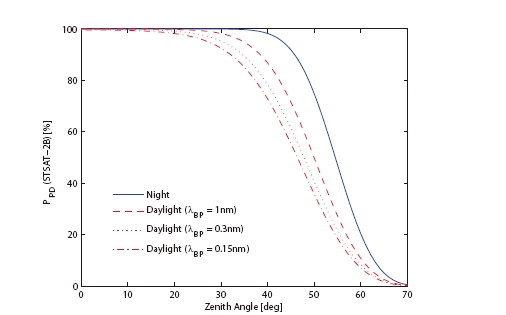
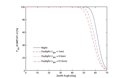
Figs. 6 and 7 show the photon detection probability of the background noise and the actual signals during the daylight and night tracking of STSAT-2B and KOMPSAT-5. In the case of STSAT-2B, the photon detection probability is drastically reduced from the zenith angle of 30˚ for the daylight tracking and 40˚ for the night tracking, and in the case of KOMPSAT-5, from 50˚ for the daylight tracking and 55˚ for the night tracking.
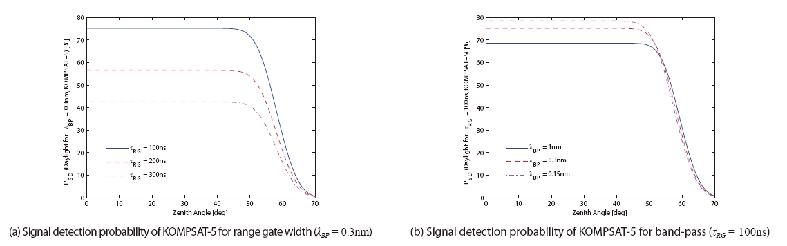
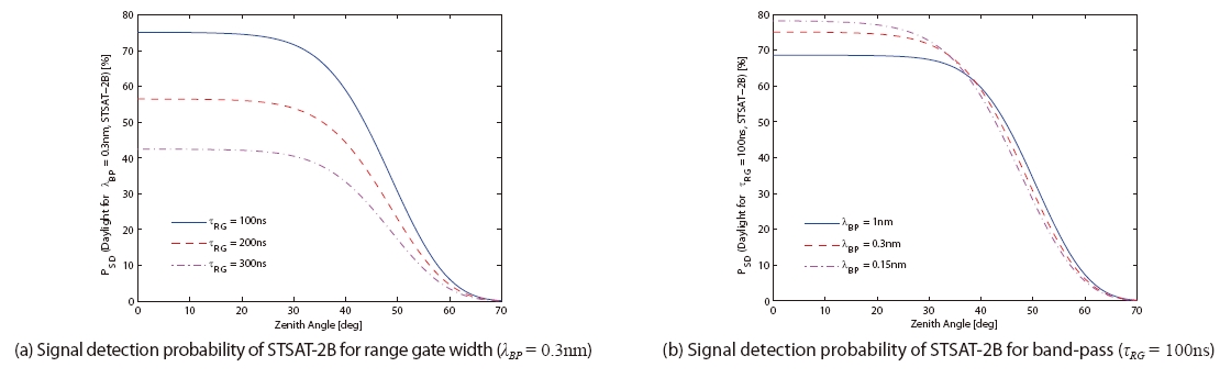
Figs. 8 and 9 show the signal detection probability of the daylight tracking of STSAT-2B and KOMPSAT-5 depending on the RG width and the band-pass width of the spectrum filters. The signal detection probability is drastically reduced from the zenith angle of 30˚ in the case of STSAT-2B and from 50˚ in the case of KOMPSAT-5, which is due to the abrupt reduction of the photon detection probability shown in Figs. 6 and 7. Actually, when the zenith angle is less than 30˚, the signal detection probabilities of STSAT-2B and KOMPSAT-5 are similar to each other if the RG width and the band-pass width are the same, but it varies a lot depending on the RG width and the band-pass width. This indicates that the RG width and the spectrum filter are important factors that determine the tracking performance of the SLR system. As shown in the Figures, as the RG width and the band-pass width are smaller, the signal detection probability is higher and it is affected more by the RG width than the band-pass width.
Since the satellite altitude and the distance between the satellite and the observatory are not related with the improvement of the ARGO-M system performance, the ARGO-M system should be designed to have small RG width and band-pass width to increase the signal detection probability, especially focusing on making the RG width small. However, the RG width setting is affected by the orbit prediction precision the most although it is affected by the general system characteristics including the orbit prediction precision timing system. Recently, the International Laser Ranging Service (ILRS) analysis center provides the consolidated prediction format type of
predicted ephemeris which improves the precision of the predicted ephemeris in Tuned IVs used for 20 years and realizes the laser ranging for the lunar and planet exploration (Ricklefs 2006). Hence, many SLR systems tend to reduce the RG width to improve the measurement precision and the RG width should be determined considering this tendency in the ARGO-M system development.
If the band-pass width of a spectrum filter becomes larger, the actual signal detection probability is reduced because the noise detection probability is also increased along with the link budget. Even though the ARGO-M system should be designed to have small band-pass width, it is limited because of the laser pulse width and Doppler effect due to the signal characteristics. Thus, general SLR system uses 1-0.3 nm of band-pass width for satellites but 0.1nm for lunar laser ranging. Since the signal detection probability is very sensitive to the background noise, NASA next generation SLR (NGSLR) uses different spectrum filters for the laser ranging at night, at dawn and in the evening. It is also recommendable for the ARGO-M system to use the spectrum filters with various band-pass widths depending on the intensity of the background noise at the observatory.
The ARGO-M of KASI is the first SLR system that is developed in Korea for the space geodesy research and the laser ranging of the satellites with LRA. The link budget depending on the spectrum filters was calculated to analyze the performance of ARGO-M in the daylight and night tracking of STSAT-2B and KOMPSAT-5. The link budget of KOMPSAT-5 was about 7 times larger than that of SATSAT-2B despite its smaller transmission gain due to the difference in the divergence angles of the transmitting beam. The main reason is caused by the distance between the observatory and the satellites. As the altitude of the satellites was smaller, the average number of detected photons was drastically decreased. In the case of daylight tracking, the noise detection probability was lager as the band-pass width of the spectrum filters and the RG width of the time filters were larger, while the signal detection probability was inversely proportional to them and affected more by the RG width than the band-pass width. Therefore, the RG width of the time filters and the band-pass width of the spectrum filters should be designed to be small in order to elevate the daylight tracking performance of the ARGO-M system. However, the general system characteristics such as the orbit prediction precision and timing system should be considered in determining the RG width, and the limiting conditions of the laser pulse width and Doppler effect should be taken into account in determining the band-pass width so that the system have the best performance.