Millimeter-wave receivers used in radio astronomy should have very low noise performance because the signals from celestial sources are extremely weak. This property demands that cryogenically cooled components be used in radio astronomy receiver systems. For the cryogenic operation high electron mobility transistor (HEMT), low noise amplifiers (LNAs), and superconductor- insulator-superconductor (SIS) mixers are cooled with 20 K and 4 K closed-cycle refrigerator, respectively. One of the most critical components in radio astronomy receiver system is a linear or circular polarizer depending on observation methods and radio sources. In particular very long baseline interferometry (VLBI) observations are generally performed through circular polarization. Septum polarizers are widely used to separate dualcircular polarized signals in VLBI receiver systems and KVN 22 and 43 GHz band receiver systems also employ septum polarizers (Chung et al. 2009). But septum polarizers have relatively narrow bandwidth which is typically less than 25% and become difficult to be assembled when operation frequencies increase. Another method of discriminating dual-circular polarization is to use an orthomode transducer (OMT) combined with a 90o differential phase shifter. The OMT can separate two linearly orthogonal signals and tends to have a very wide bandwidth, even greater than 40% (BØifot et al. 1990). A 90o differential phase shifter is to convert circularly polarized waves into linearly and orthogonally polarized ones by making 90-degree phase difference between two orthogonal polarization modes. There exist several techniques to implement the differential phase shifter. A dielectric plate in a circular waveguide for 90o or 180o differential phase shifter has been used in lower frequencies where the insertion loss is not significant. Square waveguidebased differential phase shifters with dielectric loading or corrugation on waveguide inner walls have been reported (Lier & Schaug-Pettersen 1988). Since a polarizer attached to LNA or SIS mixer is cooled at cryogenic temperature (20 K or 4 K), a differential phase shifter with dielectric loading is not appropriate for radio astronomical receiver systems due to deformation of dielectric material. Thus, differential phase shifters with corrugation are usually made out of all-metal for compact and robust structure in cryogenic environment. It is important for a 90o differential phase shifter to have wide bandwidth property because the operation bandwidth of a polarizer using OMT depends strongly on the phase shifter. The dual-circular polarizer development for KVN 129 GHz band consists of two parts: 90o differential phase shifter and OMT. As mentioned above, a critical part for the wide-band operation of the polarizer is the 90o differential phase shifter design. Since the designs of the two parts can be carried out independently, we address only the design and simulation of the 90o differential phase shifter in this paper and the OMT design will be introduced later. The design and theoretically calculated performance of a prototype 90o differential phase shifter for KVN 129 GHz band operation are described in this paper.
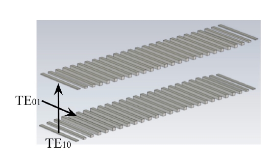
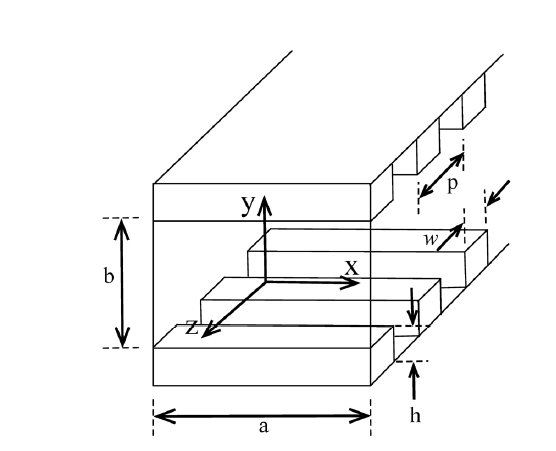
A circularly polarized wave can be decomposed into two orthogonal linear modes with 90o phase difference. As a critical part of the dual-circular polarizer, the differential phase shifter is to make the 90o phase shift between the two orthogonal modes. A structure of the differential phase shifter employed in this paper is shown in Figs. 1 and 2. An incident circularly polarized wave consists of (TE10) and (TE01) modes. The differential phase shifter is made of a square waveguide with two opposite walls loaded with corrugations and the side walls are assumed to be smooth metals. That structure can be said to be rather a conventional square waveguide phase shifter.
There have been several works concerning differential phase shifters which have transverse corrugations loaded on four walls of a rectangular waveguide (Tucholke et al. 1986, Srikanth 1997). It was reported that the differential phase shifter with four-wall corrugation rectangular waveguide could provide wider bandwidth for phase shift of 90o ± 3o compared to the conventional differential phase shifter which has corrugations loaded only on two walls in rectangular waveguide. The reason behind using the conventional phase shifter structure in this paper is as follows: the frequency bandwidth needed for KVN 129 GHz band is less than 30% for a 0.5 dB axial ratio and the two-wall corrugated waveguide can decrease manufacturing complexity compared to the differential phase shifter which has corrugations on four walls.
The geometry of a corrugated square waveguide is shown in Fig. 2 where Ω,
where
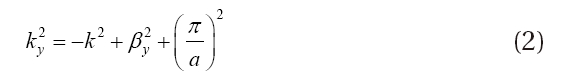
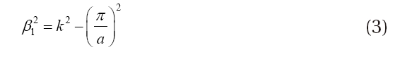
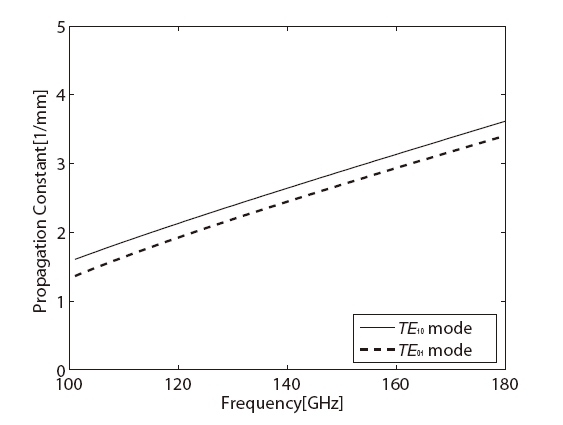
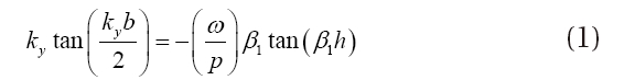
Here βy is the propagation constant for the y-polarized mode (TE10) and k is the wavenumber 2πλ. Eq. (1) can be numerically solved to determine the propagation constants for y-polarized wave. The propagation constant for (TE01) mode can be simply calculated by assuming the smooth walled square waveguide. As the two orthogonal modes (TE10 and TE10) travel inside the square waveguide loaded with corrugations, the different propagation constants of the two modes result in the phase shift between them. One can thus have 90o phase shift between the two orthogonal modes by carefully choosing corrugation dimensions described in Fig. 2. Since 3D electromagnetic simulation is generally a time consuming job, it is convenient that one estimates some range of corrugation dimensions by solving Eq. (1) for 90o phase shift between (TE10) and (TE01)modes at the design frequency band before performing the simulation of differential phase shifter
with corrugated square waveguide.
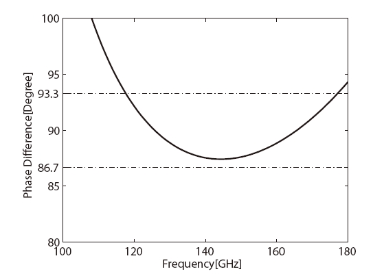
The calculated propagation constants for the two orthogonal modes (TE10 and TE10) as a function of frequency are shown in Fig. 3. Using the calculated propagation constants, one can derive the phase difference between (TE10)and (TE01) modes. For having an axial ratio of 0.5 dB over the operation frequency band, the differential phase shift must be within 90o ± 3.3o. By changing the corrugation parameters of Ω,
3. SIMULATION OF 90o DIFFERENTIAL PHASE SHIFTER
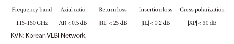
The 90o differential phase shifter has been designed using CST MICROWAVE STUDIO (MWS) which is a time domain-based three dimensional electromagnetic simulation software. Table 1 shows the design goal of the 90o differential phase shifter for KVN 129 GHz band operation. The polarization leakage has an adverse effect on the radio astronomical polarization observations. Even though one can correct the polarization data after the polarization leakage characteristics are determined, it would be better to minimize the instrumental error such as polarization leakage for increasing the precision of the observation. Many radio interferometry observatories like VLA use the axial ratio specification of 1 dB which corresponds to D-term of 6.1%. The phase shift error is the dominant factor in the polarization leakage (or D-term) and there is little contribution from the OMT. Other contributions from the feed horn and radio telescope quasi-optics are generally unknown factors which are believed to be smaller than the polarizer itself. It would be recommended to keep the polarization leakage caused
[Table 1] Design specifications for the 90o differential phase shifter for KVN 129 GHz band.

Design specifications for the 90o differential phase shifter for KVN 129 GHz band.
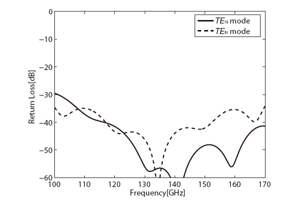
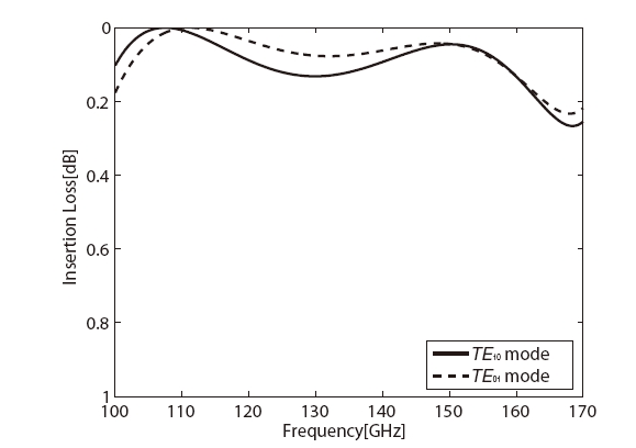
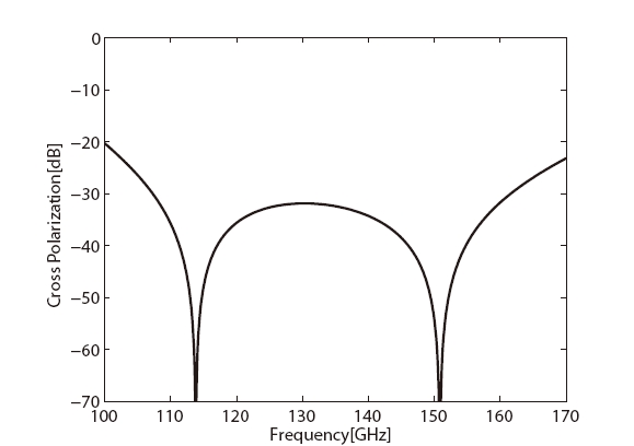
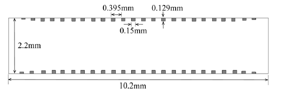
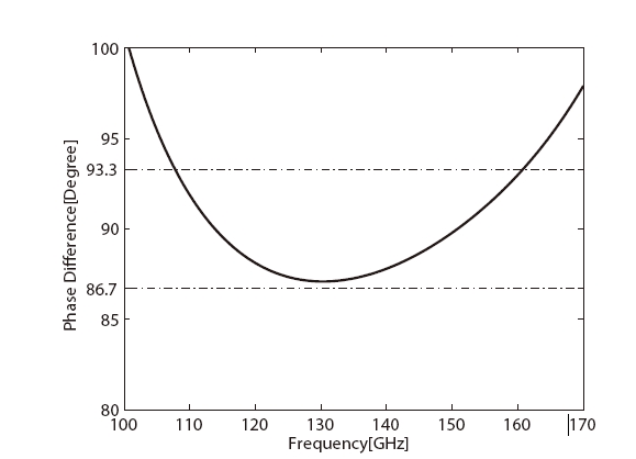
by the polarizer as low as possible in order to make the total axial ratio less than 1 dB. Technically it is difficult to make the 90o phase difference error much below 3.3o across a wide frequency band. That the axial ratio of 0.5 dB (or phase shift error of 3.3o about 90o) is set for the design goal of the corrugated 90o phase shifter in this paper is a compromise between the technical difficulties and the observational requirements. CST MWS allows one to use Visual Basic for Application (VBA) in the software, which consists of standard language elements and CST MWS specific language extensions. A VBA program was written to efficiently define the geometry of the 90o differential phase shifter. A starting point of the simulation is based on the dimensional parameters obtained by solving the characteristic equation of two-wall corrugated square waveguide even though the calculation described above did not include higher order modes of propagation. By iteratively changing the dimensions of the corrugations, the specified performance of the 90o differential phase shifter could be achieved. In the simulation the inner surface of the differential phase shifter was assumed to have a conductivity of copper (5.96 × 10⁶ s/m) instead of a perfect conductor. The detailed geometrical dimensions of corrugations and square waveguide are described in Fig. 5. Ramp sections are incorporated at the input and output of the 90o differential phase shifter in order to have a good return loss (Tucholke et al. 1986). Those ramp sections make the waveguide length of the differential phase shifter different from the length determined by using the numerical solution of the characteristic equation. Simulated 90o differential phase shift between the two orthogonal modes is shown in Fig. 6 and the axial ratio specification (<0.5 dB) is achieved over 108-160 GHz, which is wider than the design frequency band. Fig. 7 indicates that the return losses for the two orthogonal modes of the differential phase shifter are as low as -30 dB across the design frequency band. The insertion losses for the two modes are also better than -0.2 dB as shown in Fig. 8. A cross-polarization is caused by the deviation of the differential phase shift from 90o. Assuming the amplitude match between the two orthogo
nal modes, the cross-polarization in decibel is given by
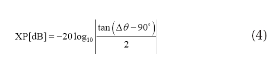
where Δθ is the differential phase shift between the two modes.Fig. 9 shows the calculated cross-polarization of the 90o differential phase shifter.
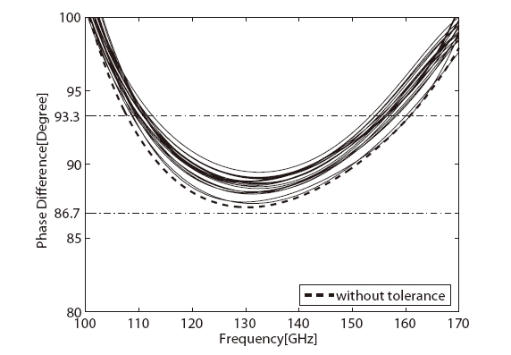
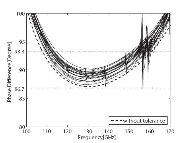
Simulations of the 90o differential phase shifter showed that a small dimensional change of the corrugations might cause a significant variation of the performance. The sensitivity of the 90o differential phase shifter to fabrication tolerances is believed to be critical because it is inevitable that the manufacturing process imposes somewhat dimensional disparity between the fabricated differential phase shifter and the designed one. Therefore, the tolerance analysis concerning how much the performance of the 90o differential phase shifter could deteriorate for given manufacturing tolerances is needed before fabricating the differential phase shifter. The tolerance analysis adopted in this paper is similar to the method developed by Liang et al. (1992). That is, first one randomly chooses variations of pitches, depths, widths of corrugations within a given tolerance. The simulation is then performed using CST MWS and the frequency bandwidth for phase difference of 90o ± 3.3o is obtained. These steps are repeated for predefined times to obtain the worst performance and a tendency of the performance of 90o differential phase shifter with respect to manufacturing tolerances can be found. Since the entire simulation is very time consuming, the simulations were repeated 20 times for manufacturing tolerances of ±2 μm and ±4 μm, respectively. Figs. 10 and 11 show the results of the tolerance analysis for the designed 90o differential phase shifter. Given axial ratio of 0.5 dB frequency bandwidths for the differential phase shift of 90o ± 3.3o are 113-153 GHz for manufacturing tolerances of ±2 μm and approximately 115-150 GHz for ±4 μm, respectively. The state of the art 3-axis CNC milling machine (e.g., Kern Model 44 micromilling system) has the part measured accuracy of ±2 μm. It is possible to fabricate a 90o differential phase shifter of which the performance meets the design specification.
The simulation in order to obtain the design parameters of the 90o differential phase shifter for KVN 129 GHz band has been performed by using 3D electromagnetic simulation software, CST MWS. The set of parameters determined by solving the characteristic equation for the corrugated square waveguide were used as a starting point for 3D electromagnetic simulation. During the simulation the dimensional parameters are refined to get the final result. The calculated frequency bandwidth for the axial ratio specification (<0.5 dB) is wider than the design frequency bandwidth, 115-150 GHz. In addition, the simulation result showed that the return and insertion losses for the two orthogonal modes of the differential phase shifter are better than -30 dB and -0.2 dB, respectively. The calculated performance of the 90o differential phase shifter is adequate for KVN 129 GHz band operation. Compared to the septum polarizer which is generally made by using split-block technique (Chung et al. 2009), manufacturing of the differential phase shifter with corrugations loaded on the walls is not affected by the alignment precision because electroforming technique is employed for the fabrication. A tolerance analysis of the designed 90o differential phase shifter was made to test the robustness of the phase shifter’s design for dimensional variations. Even though tighter tolerances can give less sensitivity of the performance to fabrication accuracy, a manufacturing tolerance of ±4 ㎛ is enough to reach the design specification of the 90o differential phase shifter at the design frequency range.
The design of the 90o differential phase shifter was made by trial-and-error method because the corrugated phase shifter has too many parameters to use the internal optimization function provided in CST MWS. It is difficult to say that the obtained performance of the 90o differential phase shifter in this paper is an optimized result. Thus, there is still room for further improvement of the 90o differential phase shifter’s performance for KVN 129 GHz band. There were attempts to develop broadband 90o differential phase shifters with various approaches including dual-depth E-plane corrugated square waveguide (Arndt et al. 1984) and transverse corrugations on all four walls of a rectangular waveguide (Lier & Schaug-Pettersen 1988, Srikanth 1997). Neither of approaches employed a non-uniform corrugation structure which has already been used in corrugated horn antennas (Jamnejad & Hoorfar 2004). Traditional optimization methods or using the internal optimization function of CST MWS are not appropriate for waveguide structure loaded with non-uniform corrugations which is a complex multivariable problem. For such an optimization problem it is necessary to use global optimization techniques which can handle a large number of optimization parameters. One of these techniques, which is widely used in electromagnetic- optimization problems, is genetic algorithms. Genetic algorithms and the similar optimization technique have been successfully applied to the design of various corrugated horn antennas (Sinton et al. 2002, Hoorfar 2007). It is believed that applying genetic algorithms to the design of 90o differential phase shifter with non-uniform corrugated walls may open the door to a feasibility of making the bandwidth of differential phase shifter wider than ever.