Korean government made clear that it would make efforts to carry out full-fledged research into space exploration with the aim of developing a Lunar Orbiter (LO) from 2017 to 2020 in the detailed implement guidance of the space development project established in 2007 (Lee 2009). To make the plan realized, basic researches into a space communication link are essential (Kim et al. 2009). However, local researches in Korea were focused on the near-earth satellite communication links and the researches on the deep space communications were hardly founded. This paper designs and analyzes the downlink between a LO and an Earth Station (ES) in space communications system for lunar exploration, and suggests requirements for the communication link design with conforming to international recommendations.
In general, among the losses in the calculation of a space communication link budget between the LO and the ES, the largest one is the free space loss comes from the distance between the earth and the moon. Furthermore, an accurate link model should be made up in order to analyze the performance in a more accurate way, with all the other elements influencing on signal quality. In this paper, we design the model of a space communications system considering almost all elements to affect the downlink performance of the space communications system between the LO and the ES, based on detailed requirements by CCSDS (the Consultative Committee for Space Data Systems, 2007), and verify the results with reference to the foreign operation cases of NASA (National Aeronautics and Space Administration) DSN (Deep Space Network) (Slobin 2006, Sniffin 2002, 2008). According to the CCSDS, we assume that the communication links have the line of sight path between the LO and the ES for S, X, Ku, and Ka bands, and an uncoded OQPSK signal is considered for a telemetry transmission. Also, a required target BER (Bit Error Rate) in the downlink space communications systems is assumed to be 10-5. We calculate the
The remainder of this paper is organized as follows: section 2 introduces a system model, section 3 analyzes the performance of the downlink space communications system, and the final section gives conclusions.
In a receiver, the thermal noise is always existed caused by the motion of the internal electrons which are affected by the resistance and the temperature of the components. The thermal noise takes place in almost all components from the large-size antenna to the small-size components, and is represented as the equivalent noise temperature. In a communication system, the thermal noise is a basic reason for the performance degradation. Moreover, in a space communications system, the thermal noise contributes as a critically detrimental effect because the received signal strength is extremely low due to a long transmission distance. The thermal noise power

where
The free-space loss of a communication link in the line of sight is (Roddy 2006)

where [
When electromagnetic signals pass through the atmosphere of the earth, the signal power is weakened by energy absorption, scattering, and reflection of components in the atmosphere.
The atmosphere has many electrons and cations at an altitude of over 50 km. This area is neutral on the whole, but generates a kind of ionized plasma, which is called ionosphere. In the ionosphere, free electrons which are non-uniformly distributed, make signal attenuation and change their phase resulting in one of the losses.
Rain attenuation drastically changes depending on space and time that it cannot be predicted easily. However, it is statistically estimated with the help of probability characteristics considering geological location, climate, topography, season and rainfall.
In low frequency bands, rain attenuation has little influences, but in high frequency bands, power loss rapidly increases. Especially, in a over 20 GHz band, signal absorption and scattering by rainfall are so serious that severe attenuation occurs (ITU-R 2003). In case of designing a space communications system in high frequency band, it is required to carefully take the effect of rain attenuation into consideration due to geographical characteristics like frequent localized torrential downpours.
Electromagnetic waves from the sun are reflected by the surface of the moon and go towards the earth. Among them, visible rays are seen with the naked eye. The rays of the sun are kinds of wide band electromagnetic waves. They act as an interference and effect on the communication link between the earth and the moon. The loss caused by them is assumed to be 4 ∼ 6 dB (Johannsen et al. 1974, Park et al. 2009).
Antenna circuit loss is caused by imperfect impedance matching between components in antennas, cables, waveguides, filters, and couplers. The amount of circuit loss can be changed, depending on a way of designing and connecting hardwares. In this paper, we assume the circuit loss of the ES follows the standard of the NASA DSN. The circuit loss of the LO is assumed to be the same as that of the ES (Slobin 2008a,b, 2009).
In general, a space communications system uses a parabolic antenna for more antenna gains. Pointing loss statistically comes about 0 ∼ 1 dB, because the transmitter and the receiver antennas do not be correctly aligned each other.
For an uncoded OQPSK signal, the required

where

In order to compare the calulated


where
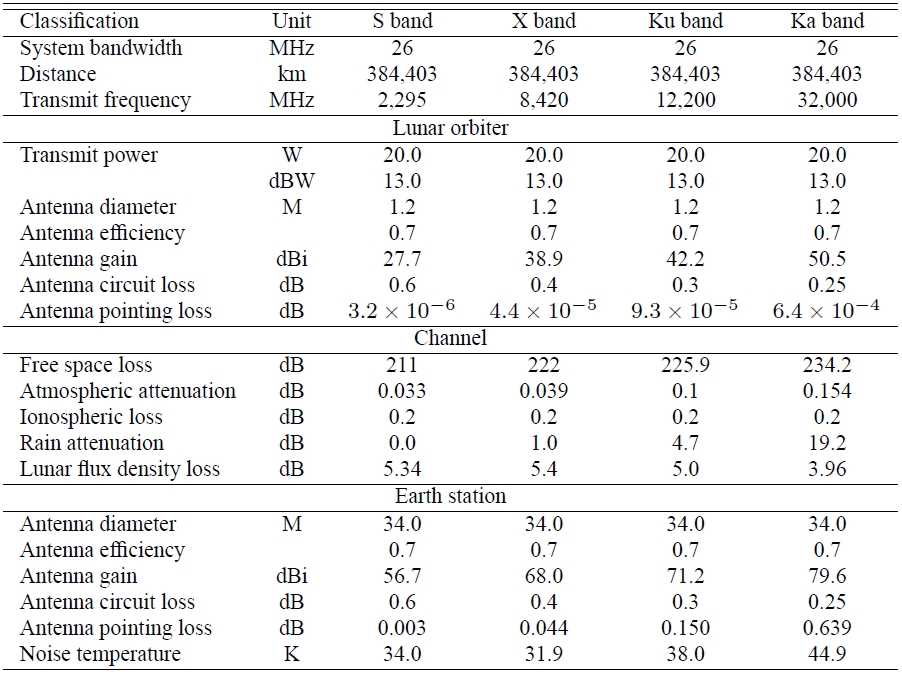
[Table 1.] High-speed downlink model.

High-speed downlink model.
High data rate is required to transmit the multimedia data collected by the LO through a downlink. Chang'e 1 of China and Selene of Japan for lunar explorations are planning to set the maximum downlink data rate as 2 Mbps and 10 Mpbs, respectively (Hayashi et al. 2003, Hisahiro et al. 2005, Yu et al. 2005). Also, the NASA DSN sets the data rate up to 52 Mbps (Tai 2007). Therefore, in this paper, we set the maximum downlink data rate as 52 Mbps for the mutual compatibility of NASA DSN standards. The S, X, Ku, and Ka transmit frequency bands are also set as 2.295, 8.42, 1.22, and 32 GHz, respectively, conforming to the CCSDS standards.
It is assumed that a Lunar Orbiter's Antenna (LOA) diameter is 1.2 m; transmit power of the LO is 20 W; an Earth Station's Antenna (ESA) diameter is 34 m, referring to the BWG antenna DSS-24 in Goldstone, USA; and the noise temperature of the ESA in S, X, Ku, and Ka bands are distributed between 34∼44.9 K (Slobin 2008a). The antenna gain of a parabolic antenna can be calculated as (Roddy 2006)

where η means aperture efficiency, the value between 0.55 ∼ 0.73;
3.2 Link performances for data rates
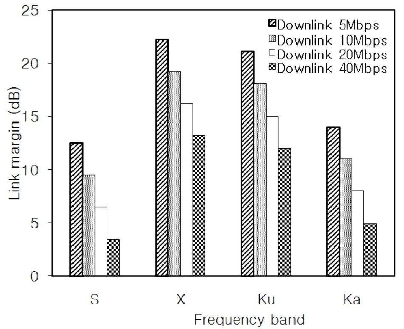
In this section, we analyze the link performances for data rates of the downlink with the referenced 34 m ESA and 1.2 m LOA. Figure 1 shows a link margins for the data rates from 5 Mbps to 40 Mbps, based on the model in Table 1. Because we assumed uncoded OQPSK, frequency efficiency is 2 bps/Hz. Thus the required bandwidths for the data rates of 5, 10, 20, and 40 Mbps are 2.5, 5, 10, and 20 MHz, respectively. From the Figure 1, we see that all data rates in the downlink have sufficient link margins for maintaining a reliable communication link in all frequency bands. As the data rate increases, however, the link margin decreases.
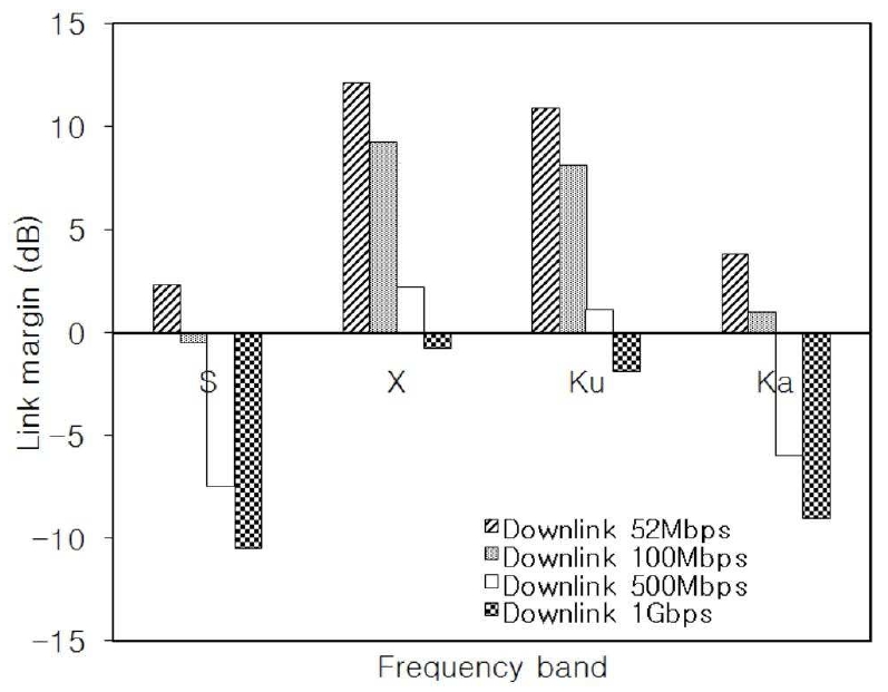
Figure 2 shows the link margins for the downlink data rates of 52 Mbps, 100 Mbps, 500 Mbps, and 1Gbps with system bandwidths of 26, 50, 250, and 500 MHz, respectively in S, X, Ku, and Ka bands. Only the data rate of 52 Mbps can satisfy the link margin requirement in all frequency bands. In S band, data rates of 100 Mbps, 500 Mbps, and 1 Gbps; and in X and Ku bands, data rate of 1 Gbps do not satisfy the condition for the reliable communication.
3.3 Link Performance for antenna sizes
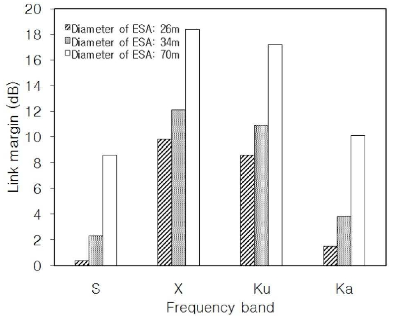
Even we assumed that the reference diameter of the ESA is 34 m, based on the DSS-24, we need to analyze the link performance for the ESA diameters of 26 and 70 m, which are actually used for lunar exploration in the USA. Figure 3 shows the downlink performance for the ESA diameters of 26, 34, and 70 m at the data rate 52 Mbps with the referenced diameter of 1.2 m in LOA. As the ESA diameter increases, the link performance becomes better due to the increased receiver antenna gain. The ESA diameters of 26, 34, and 70 m meet the sufficient link margins for the stable communication link in all bands.
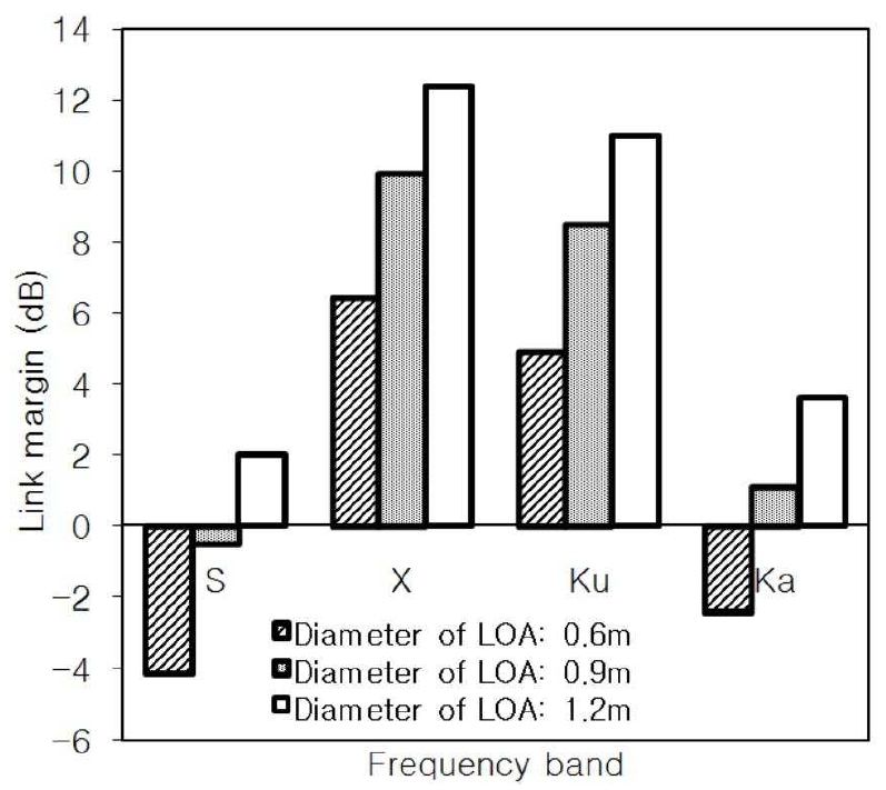
Figure 4 shows the link performance for the LOA diameters of 0.6, 0.9, and 1.2 m at the data rate 52 Mbps with the referenced diameter of 34 m in ESA. As the LOA diameter increases, costs of launching an orbiter will be increased. But the larger antenna size can provide better performance due to the increasing EIRP (Effective Isotropic Radiation Power) under a fixed transmit power. The LOA diameters of 0.6 and 0.9 m in S band; and 0.6 m in Ka are insufficient to establish the reliable communication link. The LOA diameters of 0.6, 0.9, and 1.2 m in X, Ku bands provide sufficient link margin.
3.4 Link Performance for transmit powers of a LO
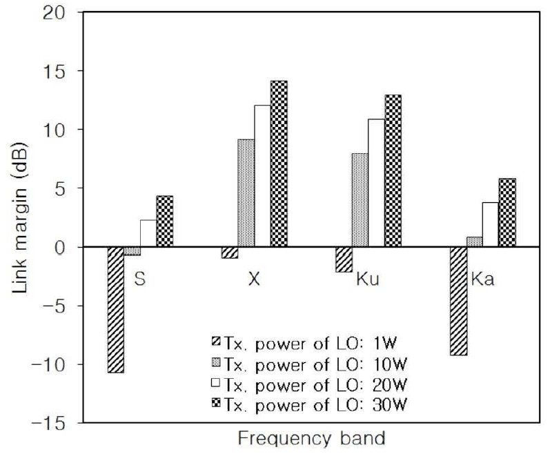
Figure 5 shows the downlink performance when the transmit powers of a LO are 1, 10, 20, and 30 W at the data rate 52 Mbps with the referenced diameters of 34 m in ESA and 1.2 m in LOA. In general, the LO's transmit power is a below 20 W because of the limited power capacity of the LO. But we also consider LO's transmit power of 30 W for comparison. As the transmit power of the LO increases resulting in higher EIRP, the link performance is improved. The LO's transmit powers of 1W in all bands; and 10 W in S band do not meet the condition for reliable communication. The LO's transmit powers of 20, 30 W provide the sufficient link margin for the stable communication link in all bands.
3.5 Trade-offs between size of a LOA/an ESA and transmit power
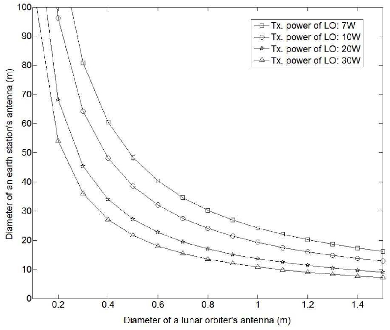
In sections 3.3 and 3.4, we analyzed downlink performances with different antenna sizes and transmit powers. In this section, we examine the trade-offs between antenna diameters and transmit powers at the data rate 52 Mbps, with the model in Table 1. Also, we focused on the trade-offs in the Ka band because the antenna gain is more sensitive than in any other band as shown in (7). Figure 6 shows the relationship between diameters of the ESA and the LOA for the different transmit powers 7, 10, 20, and 30 W of the LO in the Ka band. Instead of the transmit power of 1 W of the LO in the previous section, we uses the transmit power of 7Wbecause the downlink performance is drastically degraded with the transmit power of 1 W.
The increase in the transmit power of the LO is limited by the size of the solar arrays and available power. As the diameter of the LOA increases, the volume of the LO becomes larger resulting in higher launching costs. When the transmit power of the LO is 20 W and the diameter of LOA is 1.2 m, the diameter of 11.4 m in an ESA is required for reliable communications. However, when the transmit power of the LO is 10 W and the diameter of LOA is 0.6 m with realistic limitations on the launched LO's volume, a large-size ESA diameter of at least more than 32 m is required.
If a channel coding technique is adopted, the antenna sizes and transmit powers of a LO and an ESA can be reduced as much as obtainable coding gain. Multiple antennas based on signal processing and adaptive modulation techniques are also expected to reduce the design burdens of a LO and an ES for reliable communications.
In this paper, we designed and analyzed the downlink between a LO and an ES in space communications system for lunar exploration, and suggested requirements for the communication link design with conforming to international recommendations. A simple way of improving the downlink performance is either to increase in the transmit power of a LO or in the diameters of an ESA or a LOA. However, there are some realistic limitations for the LO. The available power generated by solar cells of a LO are limited, so that the increase in transmit power of a LO has a limit. As the diameter of a LOA increases, the costs of launching a orbiter become higher. Considering these limitations, the trade-offs between the transmit power of a LO and the diameter of an ESA and a LOA were analyzed. When the transmit power of the LO is 20 W and the diameter of LOA is 1.2 m, the diameter of 11.4 m in an ESA is required for reliable communications. However, when the transmit power of the LO is 10 W and the diameter of LOA is 0.6 m with realistic limitations on the launched LO's volume, a large-size ESA diameter of at least more than 32 m is required.
The results provided in the paper are expected to be primitive data for designing a space communications system between an ES and a LO for Korean lunar exploration in the near future.