Prediction of unsteady flow fields aroundhelicopters is one of the most difficult problems inmodern CFD. The tip vortex interacting with rotorblades causes Blade-Vortex Interaction (BVI)which generates highly directional impulsive noiseand sudden change in the blade aerodynamicloading. The aerodynamic interaction between therotor wake and the fuselage results in unsteadyloading on the fuselage, and causes a fuselagevibration problem. These aerodynamic interactionssignificantly affect on the performance ofhelicopters and can cause structural damage.
Therefore, precise understand of the aerodynamicinteraction between rotor, fuselage, and othercomponents is needed. However, the existence offuselage underneath the rotor amplifies thecomplexity of analysis, and the unsteadiness of therotor wake and the asymmetric nature of the rotordisk loading make it difficult to predict the flowfield around the full helicopter configuration.Several research works have been conductedpreviously to calculate the complicated unsteady flowfields around helicopters involving mutual aerodynamicinteraction between the rotor and the fuselage. As thetraditional way, lifting line/free-wake methods coupledwith potential theory have been used to model therotor blades and the fuselage [1? 3]. These methodsare computationally inexpensive and providefundamental understanding of the rotor fuselagephenomena, but are limited to inviscid flows.
Several research works have been conducted previously to calculate the complicated unsteady flow fields around helicopters involving mutual aerodynamic interaction between the rotor and the fuselage. As the traditional way, lifting line/free-wake methods coupled with potential theory have been used to model the rotor blades and the fuselage [1-3]. These methods are computationally inexpensive and provide fundamental understanding of the rotor fuselage phenomena, but are limited to inviscid flows.
Owing to the development of high performance computers, analysis of rotor fuselage interaction became possible with the Euler or Navier-Stokes methods modeling with a simplified modeling of rotor such as the actuator disc[4, 5].
These methods provide reasonable timeaveraged/time accurate solutions, but because of thesimplified representation of the rotor, it is difficult tocapture the precise influence of the rotor wake on thefuselage and the unsteady flow features such as thetip-vortex generation, or blade-vortex interaction.
As an alternative to above-mentioned methods, a method that describes the relative motion between the rotor and the fuselage directly has been developed using either sliding mesh or structured overset mesh technique [6-8]. Through these methods, it became possible to model the both fuselage and rotor with high resolution Euler/Navier-Stokes methods. However, because of the regularity required in the grid point distribution, the overset method based on structured grids is difficult to enhance the local resolution of the solution by mesh adaptation. Also, it is known that the sliding mesh method is not robust when mesh deformation becomes severe due to large blade motion or deflection.
Recently, to overcome these limitations, the methods based on unstructured overset mesh have been widely used by many researchers, because unstructured mesh methods have an advantage of handling complex geometry and can easily improve the solution accuracy by refining cells locally as required [9-11].
In the present study, a numerical method hasbeen developed for the simulation of inviscid unsteadyflows around a complete rotorcraft configuration basedon unstructured meshes. Even though it is also possibleto simulate unsteady flowfield with viscous method, thecalculation is still expensive compared to inviscidmethod. To describe the relative motion between themain rotor, and other components, an overset meshtechnique was adopted. To enhance the spatial accuracyof the solution, a quasi-unsteady solution-adaptivemesh refinement technique was applied.
For the application of the present method,calculations were made for the rotor-fuselageinteraction of the ROBIN configuration. The resultswere compared with experimental data. As the secondapplication, the mutual interference between mainrotor, fuselage, and tail rotor of a complete UH-60configuration was investigated. The flowfield and theairloads on the rotor were examined. From the results,the characteristics of the rotor-fuselage interactionand the mutual interference effect on overall flowfieldaround a helicopter were demonstrated.
2.1 Spatial Discretization and Time Integration
The equations governing three-dimensional, inviscid, unsteady, compressible flows are the Euler equations, which can be recast in an integral form for a bounded domain
where ρ =[ ρ, ρu, ρv, ρw, ε] is the solution vector of the conservative variables for the mass, momentum and energy equations. The governing equations were discretized using a vertexcentered finite-volume method. The flow domain was divided into a finite number of control volumes surrounding each vertex, which are made of a non-overlapping median-dual cell whose boundary surfaces are defined by the cell centroid, face centroid, and mid-point of the edge. The inviscid flux term,
An implicit time integration algorithm basedon a linearized second-order Euler backwarddifferencing was used to advance the solution intime. The linear system of equations was solved ateach time step using a point Gauss-Seidel method.
On the solid surface of the fuselage and therotor blades, the flow tangency condition wasimposed. The density and the pressure on the solidsurface were obtained by extrapolating from theinterior domain. At the far-field boundary, thecharacteristic boundary condition with Riemanninvariants was used.
2.3 Unstructured Overset Mesh Technique
To handle multiple bodies in relative motion effectively, an overset mesh scheme was adopted [13]. For the overset mesh method, a search procedure is needed for the identification of donor cells that contain the verticies from the opposite overlapping mesh block. For unstructured meshes, the search should be performed for all nodes of all mesh blocks, because the nodes and the cells are randomly distributed. To overcome the large computational overhead involved in this search process, a fast and robust neighbor-to-neighbor search technique was implemented by utilizing the property of the linear shape functions [14]. Under parallel computing environment, the search may develop across the subdomain block boundary, and the amount of data information assigned to each processor may change at each iteration. To handle this varying amount of calculation load efficiently, a new data structure for parallel distributed memory machine was implemented.
Once the search process is completed, the information is used for clarifying the node type and for determining the weighting factors necessary for the interpolation. In the present overset mesh method, a distance-to-wall technique [15] was implemented for grouping active nodes and nonactive nodes. Hole cutting for determining cell types as either active, interpolation, or non-active was made based on the number of active nodes assigned to each tetrahedral cell. Then interpolation and transfer of the flow variables were made between adjacent mesh blocks. In order to reduce the error involved in the interpolation, both the cell containing the interpolation receiver and also the neighboring cells enclosing that cell were considered.
To reduce the numerical dissipation and toenhance the spatial accuracy of the solution, asolution-adaptive mesh adaptation procedure wasapplied. In the present study, a quasi-unsteadymesh refinement technique was adopted to avoidexcessive computational time required by dynamicmesh adaptation applied in a fully unsteady manner.
In this approach, as the blade rotates, cellshaving high vorticity are tagged at every time step.Once the rotor completes one period of rotation,the calculation is paused and the tagged cells aredivided. Then the refined mesh is repartitioned forload balancing and the calculation resumes. Thetagged cells are divided by adding new nodes in themiddle of six edges of each tetrahedral cell. Buffercells are also used to preserve the connectivitybetween the divided and surrounding cells.
The mesh adaptation was performed for eachindividual mesh block, independent to other blocks.
For rotors in forward flight, to retain thecalculated thrust to the experimental value and toeliminate the rotor aerodynamic moment, a rotortrim procedure was adopted. The thrust andmoment coefficients can be expressed as afunction of the collective and cyclic pitch angles.Then the equilibrium state was obtained byadjusting the trim angles iteratively using aNewton-Raphson method.
In order to reduce the large computationaltime to handle a large number of cells, a parallelcomputational algorithm based on a domaindecomposition strategy was adopted. The loadbalancing between processors was achieved bypartitioning the global computational domain intolocal subdomains using the MeTiS libraries. TheMessage Passing Interface was used to transferthe flow variables across the subdomain boundary.This load balancing was made for each sub-blockmesh, and thus was not strictly enforced for theglobal computational domain. All calculations weremade on Linux-based PC clusters having 2.5G HzIntel Core 2 Quad CPU.
Initially, calculation was made for the ROBINrotor-fuselage configuration to validate thecapability of the present method for accuratelypredicting induced downwash by the main rotor andthe rotor-fuselage aerodynamic interferencephenomena. Then the present method was appliedto a complete configuration of UH-60 helicoptercomposed of main rotor, tail rotor, and fuselage.
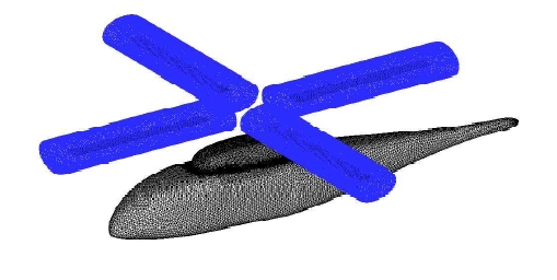
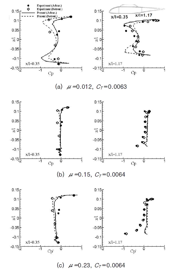
ROBIN (ROtor Body INteraction) [16] is a generic rotor-fuselage configuration consisted of a super ellipse-shaped fuselage and four blades. The blade has a rectangular platform shape with an NACA 0012 airfoil section, and is linearly twisted by -8 degrees from blade root to tip. The aspect ratio of the blade is 12.98, and the root cut-out is 0.24R. The operating blade tip Mach number is 0.523. Among the various experimental conditions, three advance ratios of μ=0.012, 0.15, and 0.23 that have the same time-averaged thrust coefficient CT=0.0064 were simulated.
In Fig. 1, the computational overset mesh consisted of five mesh blocks is presented. The main block covers the complete computational domain and the fuselage. The four sub-blocks cover each of the four rotor blades. The mesh was constructed with 284,623, 255,472, 255,472 vertices for the main block for each advance ratio of μ= 0.012, 0.15, and 0.23, respectively, and 143,654, 143,654, 143,654 vertices for the subblock for each advance ratio. After one level of mesh adaptation, the number of vertices increased to 1,241,460, 1,291,092, 1,280,972 for the main block and 227,457, 217,064, 191,346 for each
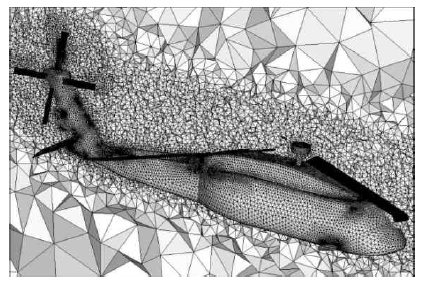
sub-block. In Fig. 2, the computational mesh distribution after mesh adaptation for μ=0.15 is presented at the fuselage symmetric plane. It is shown that small cells are distributed around the blades and the fuselage where the inference between the two components becomes most severe.
For the accurate simulation, the blade control angle setting was adjusted until the calculated thrust matched to that of the experiment. The trim of rotor was conducted with the coarse mesh. The rotor was advanced by 0.25 degrees at each time step. In the case of the advance ratio of μ=0.012, since the advance ratio is very small, the rotor trim was performed only for the collective pitch angle, and the longitudinal and lateral cyclic pitch angles were used as provided from the experiment. In table 1, comparison of the experimentally measured control angles and the The converged solution was achieved after 18, 36, 33 revolutions for each advance ratio μ =0.012, 0.15, and 0.23, respectively.
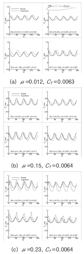
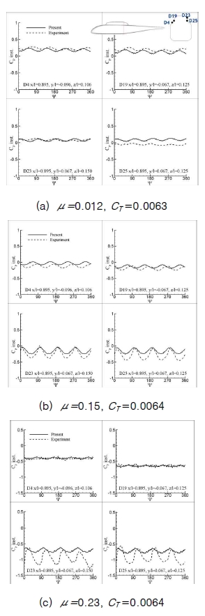
Figs. 3 and 4 show the comparison of theunsteady pressure coefficient with the experimental data. The results are represented as the modified pressure coefficient that is nondimensionalised by the rotor tip speed and multiplied by 100. It is also noticed that the experimental unsteady pressure data presented in this paper were shifted in phase by 252 degrees[17] from the original data to correct the phase delay occurred in the experiment.
In Fig. 3, unsteady pressure variations along the top center of the fuselage are compared with the experiment at four selected surface points. Although there is small deviation in the phase from the experiment, the overall results are in good agreement with the experiment for both magnitude and phase.
In Fig. 4, unsteady pressure variations around the fuselage at the streamwise station x/l=0.9 are compared with the experiment at four selected points; two at the advancing side of the fuselage, D23 and D25, and the other two at the retreating side, D4 and D19. It is shown that the results compare reasonably well with the experiment, even though the phase difference still exists between the two results.
The time-averaged pressure distributions around the fuselage at two selected streamwise locations are compared with the experiment in Fig. 5. It is shown that good comparison is made at X/l=0.35 located ahead of the pylon. At the location downstream of the pylon, X/l=1.17, the overall agreement is fair, and some deviation is observed, particularly at negative z-locations. This is presumably due to the fact that these points are under the fuselage and are affected by the structure supporting the fuselage in the experiment, which is not modeled in the present simulation.
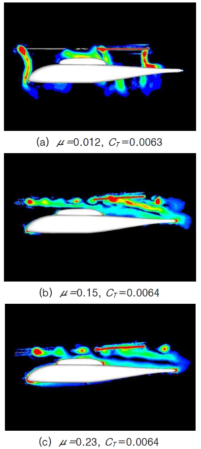
In Fig. 6, the instantaneous vorticity contours are presented at the fuselage symmetric plane. It is shown that the fuselage is completely submersed inside the rotor wake, and the tip vortex directly impinges to the fuselage at advance ratio of μ=0.012. However, as the advance ratio increases, rotor wake becomes skewed further such that only the rear part of ROBIN fuselage is affected. At the advance ratio of μ=0.15, the rear part of pylon and tail boom of fuselage is affected by the wake, but at μ=0.23, the direct impingement of wake is not observed.
3.2 Complete UH-60 Configuration
As the second validation, the mutual interaction of main rotor, fuselage, and tail rotor was simulated for a complete UH-60 helicopter configuration. The main rotor is consisted of four blades that are made of SC-1095 and SC-1094 airfoil sections, and have an aspect ratio of 15.51 [18]. The blade of the tail rotor has an aspect ratio of 3.1, and the gear ratio of the tail rotor to the main rotor is 4.62 [19]. For the simplicity of the calculation, the engine casing and the landing gear were not modeled. The calculation was made for a hovering flight condition at a blade tip Mach number of 0.65 and a collective pitch angle of 9.2° with CT/σ=0.085.
In this calculation, a simplified trim was made such that the torque produced by the main rotor is compensated by the tail rotor. For this purpose, the collective pitch angle of the tail rotor blade was adjusted until the main rotor torque Cq obtained experimentally [20], 6.7732X10⁻⁴, was cancelled by
the thrust of the tail rotor multiplied by the moment arm from the axis of the main rotor to the tail rotor. The resultant collective pitch angle of the tail rotor blade was 18.8°, which provided an anti-torque Cq of 6.7372X10⁻⁴.
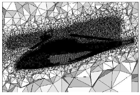
Fig. 7 shows the mesh distribution on the surface of the UH? 60 configuration and at the fuselage symmetric cutting plane. The computational overset mesh contained 504,488, 679,940, and 110,040 vertices in each mesh block for fuselage, main rotor, and tail rotor, respectively. It is shown that fine cells are distributed around the main rotor, tail rotor, and fuselage to capture the wake and the aerodynamic interaction phenomena more accurately. The total number of cells used was 6,902,466.
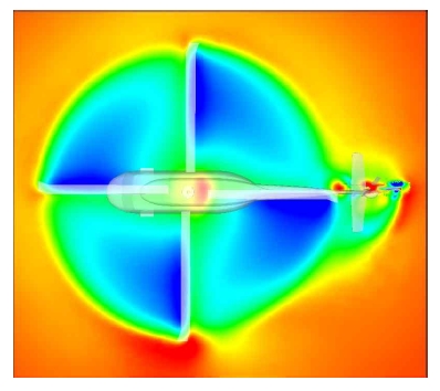
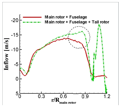
In Fig. 8, the downwash inflow contours at one chord length above the rotor disk plane is presented. It shows that the contours are slightly distorted near ψ = 0 °, showing higher inflow in this region. This is because strong sidewise flow is pumped by the tai l ro tor, which sucks in a substantial amount of downwash flow from the main rotor. As a result, the magnitude of downwash near the tail rotor along the rotor azimuth angle ψ = 0° increased. In Fig. 9, the downwash distribution along ψ = 0° at one chord length above the rotor disk plane is presented. The result is also compared with that of the rotor-fuselage configuration without the tail rotor. The figure shows that higher
downwash is obtained near the tip of the mainrotor blade and slightly off the rotor disk planedue to the interaction with the tail rotor, whichsubsequently reduces the effective angle ofattack for the main rotor blade in this region,compared to the case without the tail rotor.
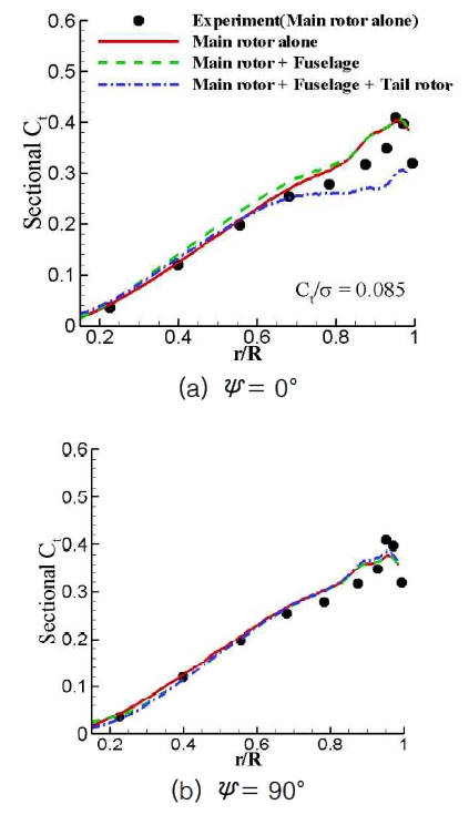
In Fig. 10, spanwise sectional thrust distributions of the main rotor blade at four azimuth angles are presented, and the results are compared with those of an isolated rotor and the rotor-fuselage configuration. It is shown that allThree calculatedresults are similar to each other, and compare well with the experiment obtained for the rotor-alone configuration. However, at ψ = 0°, the thrust loading for theconfiguration with the tail rotor is substantially lower
than the other two cases near the blade tip region.This confirms that higher induced downwash exists inthe region near the tail rotor, which reduces theeffective angle of attack and thus the blade loading.
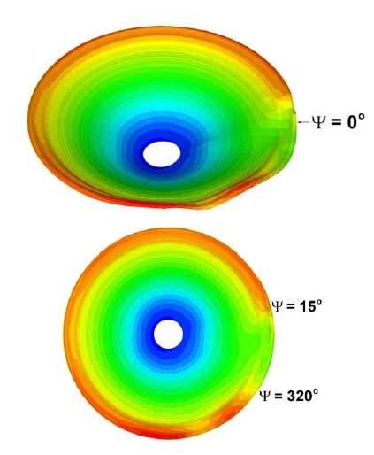
In Fig. 11, the sectional thrust contours are presented for one revolution of the main rotor. It is shown that a significant distortion of blade loading exists for the rotor azimuth angle between 320° and 15°, due to the interference with the tail rotor as described above, which could be a potential source of blade vibration.
Numerical simulations of unsteady flowsaround helicopters were conducted to investigatethe aerodynamic interaction between the mainrotor and other components. For this purpose, avertex-centered finite-volume flow solver basedon unstructured meshes has been developed. Anoverset mesh technique was used to describe therelative motion between the main rotor and othercomponents, and a quasi-unsteady solutionadaptivemesh technique is used to enhance thespatial accuracy of the solution. As the applicationof the present method, calculations were made forthe rotor-fuselage interaction of the ROBINconfiguration and for a complete UH-60 helicopterconfiguration. From the results, it was found thatsignificant mutual interference exists between themain rotor and other components, and thisinteraction affects unsteady flow characteristicsand the aerodynamic loads of helicopters. It wasalso demonstrated that the present method isefficient and robust for simulating unsteady rotorfuselageinteraction.